ISTRUZIONI PER INSTALLAZIONE USO E MANUTENZIONE
INSTALLATION, USE AND MAINTENANCE INSTRUCTION
IT
GB
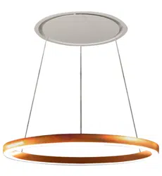
SLT973 - SLT973 LAMP
INFORMAZIONI COMMERCIALI PER I CONSUMATORI
COMMERCIAL INFORMATION FOR THE CONSUMER
2
Il simbolo sul prodotto o sulla confezione indica che il prodotto non deve essere considerato
come un normale riuto domestico, ma deve essere portato nel punto di raccolta appro-
priato per il riciclaggio di apparecchiature elettriche ed elettroniche. Provvedendo a smal-
tire questo prodotto in modo appropriato, si contribuisce a evitare potenziali conseguenze
negative per l’ambiente e per la salute, che potrebbero derivare da uno smaltimento ina-
deguato del prodotto. Per informazioni più dettagliate sul riciclaggio di questo prodotto,
contattare l’ufcio comunale, il servizio locale di smaltimento riuti o il negozio in cui è sta-
to acquistato il prodotto. Questo elettrodomestico è marcato conformemente alla Diretti-
va Europea 2012/19/EC sui riuti da apparecchiature elettriche ed elettroniche (WEEE).
IT
The symbol on the product or on its packaging indicates that this product may not be
treated as household waste. Instead it shall be handed over to the applicable collec-
tion point for the recycling of electrical and electronic equipment. By ensuring this pro-
duct is disposed of correctly, you will help prevent potential negative consequences for
the environment and human health, which could otherwise be caused by inappropriate
waste handling of this product. For more detailed information about recycling of this pro-
duct, please contact your local city ofce, your household waste disposal service or the
shop where you purchased the product. This appliance is marked according to the Eu-
ropean directive 2012/19/EC on waste electrical and electronic equipment (WEEE).
GB
1
3
2
4
5
3
6
7
4
8
9 10
12
11
13
5
14
16
17
15

INDICE
Avvertenze
Sistema d’uso
Installazione versione cappa
Installazione versione lampada
Funzionamento
Manutenzione
IT
6

AVVERTENZE
Per l’installazione del prodotto
sono richieste due persone.
I bambini e le persone inesper-
te o i disabili possono utilizza-
re l’apparecchio solo sotto la
supervisione di adulti.
L’aria raccolta non deve esse-
re convogliata in un condotto
usato per lo scarico di fumi
di apparecchi alimentati con
energia diversa da quella elet-
trica (impianti di riscaldamento
centralizzati, termosifoni, scal-
dabagni, ecc.).
Per lo scarico dell’aria da eva-
cuare rispettare le prescrizioni
delle autorità competenti.
Prevedere un’adeguata area-
zione del locale quando una
cappa ed apparecchi alimenta-
ti con energia diversa da quella
elettrica (stufe a gas, ad olio, a
carbone, ecc.), vengono usati
contemporaneamente.
La cappa aspirante evacuando
l’aria potrebbe creare una pres-
sione negativa nella stanza.
La pressione negativa del lo-
cale non deve superare i 0,04
mbar, evitando così il risucchio
dei gas di scarico della fonte di
calore.
7
Pertanto bisogna attrezzare il
locale con delle prese d’aria
che alimentino un usso co-
stante di aria fresca.
In caso di installazione con
piano cottura a gas, la distan-
za minima tra la parte inferiore
della cappa e il piano cottura
deve essere almeno 650 mm.
Nell’operazione di collegamen-
to elettrico assicurarsi che la
presa di corrente sia munita
di collegamento a terra e veri-
care che i valori di tensione
corrispondano con quelli indi-
cati nella targhetta all’interno
dell’apparecchio.
Prima di procedere a qualsiasi
operazione di pulizia o manu-
tenzione è necessario togliere
l’apparecchio dalla rete.
Se l’apparecchio non è prov-
visto di cavo essibile non
eparabile e di spina, o di al-
tro dispositivo che assicuri
la omnipolare disinserzione
dalla rete, con una distanza di
apertura dei contatti di almeno
3 mm, allora tali dispositivi di
separazione dalla rete devono
essere previsti nell’istallazione
ssa.
Se l’apparecchio è provvisto di
cavo alimentazione e di spina,
deve essere posto in modo che
la spina sia accessibile.

SISTEMA D’USO
APERTURA PANNELLO
E’ possibile aprire il pannello di copertura dei ltri
antigrasso tirandolo delicatamente come indicato
in g. 1.
Il pannello è ssato mediante tre magneti, ci
sono due cavi di sicurezza da sganciare per
rimuovere completamente il pannello dal pro-
dotto.
Per un adeguato funzionamento si consiglia di in-
stallare il prodotto ad una distanza massima, dal
livello del pavimento, di 2000 - 2100 mm.
Prima di procedere nell’installazione dell’appa-
recchio vericare che tutti i componenti non siano
danneggiati, in caso contrario contattare il riven-
ditore e non proseguire con l’installazione.
Utilizzare un tubo di evacuazione aria che abbia
la lunghezza massima non superiore a 5 metri.
- Limitare il numero di curve nella canalizzazio-
ne poiché ogni curva riduce l’efcienza di aspi-
razione equiparata a 1 metro lineare. (Es: se si
utilizzano n°2 curve a 90°, la lunghezza della ca-
nalizzazione non dovrebbe superare i 3 metri di
lunghezza).
- Evitare cambiamenti drastici di direzione.
- Utilizzare un condotto con diametro da 150mm
costante per tutta la lunghezza.
- Utilizzare un condotto di materiale approvato
normativamente.
Evitare l’uso di materiali che
causano ammate (ambè)
nelle immediate vicinanze
dell’apparecchio.
Nel caso di fritture fare partico-
larmente attenzione al pericolo
di incendio che costituiscono
olio e grassi. Particolarmente
pericoloso per la sua inam-
mabilità è l’olio già usato. Non
usare griglie elettriche scoper-
te.
Per evitare un possibile rischio
di incendio attenersi alle istru-
zioni indicate per la pulizia dei
ltri antigrasso e la rimozione
di eventuali depositi di grasso
sull’apparecchio.
8

9
INSTALLAZIONE
VERSIONE CAPPA
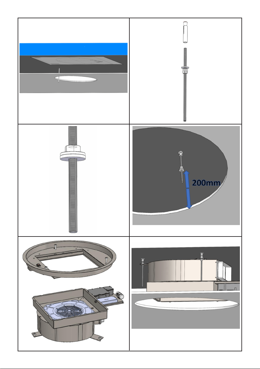
Per l’installazione di questo prodotto è necessa-
rio creare un ribassamento in cartongesso, man-
tenendo almeno 220mm di distanza tra lo stesso
ed il softto solido.
Il materiale in dotazione al prodotto permette di
installarlo su ribassamenti che vanno da 220mm
(g. 2) a 300mm (g. 3) di distanza tra il carton-
gesso ed il softto solido.
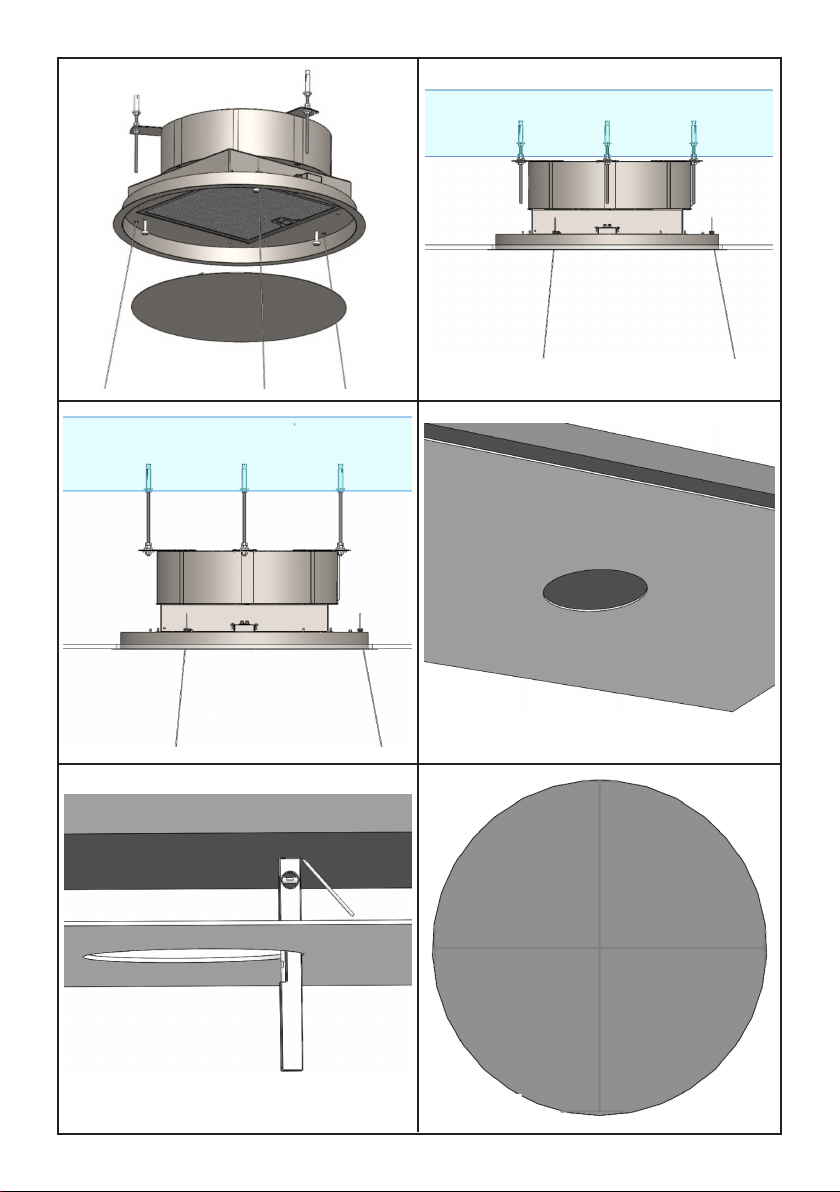
Occorre realizzare un’apertura circolare nel car-
tongesso, del diametro pari a: 510mm (g. 4)
Utilizzando una livella ed una matita riportare le
quattro estremità della foratura creata nel carton-
gesso, direttamente nel softto solido, vedi g. 5,
tracciare quindi delle rette perpendicolari come
da g. 6, al ne di trovare il centro della foratura.
Posizionare la dima di foratura fornita in dotazio-
ne, facendo coincidere il centro della dima con il
centro degli assi tracciati in precedenza (g. 7).
Utilizzando una matita tracciare le tre forature da
effettuare nel softto solido.
Prima di tracciare le foratura da effettuare, è
possibile ruotare la dima di foratura al ne di
orientare l’uscita aria del ventilatore nella di-
rezione desiderata. Nella dima di foratura è in-
dicata la posizione dell’uscita aria del ventilatore.
Effettuare le tre forature nel softto solido utiliz-
zando una punta elicoidale con diametro 8mm.
Inserire gli inserti metrici forniti in dotazione, nelle
forature realizzate.
Inserire le barre lettate negli inserti metrici pre-
cedentemente installati.
Avvitare le barre lettate utilizzando due dadi,
come da g. 8, agire nel dado sotto per avvitare
la barra lettata.
Inserire un ulteriore dado, una rondella metallica
e la rondella in plastica di bloccaggio come da
gura 9. E’ determinante, ai ni di una corretta
installazione, posizionare la rondella metalli-
ca a 200mm di altezza dalla supercie inferio-
re del cartongesso, vedi g. 10.
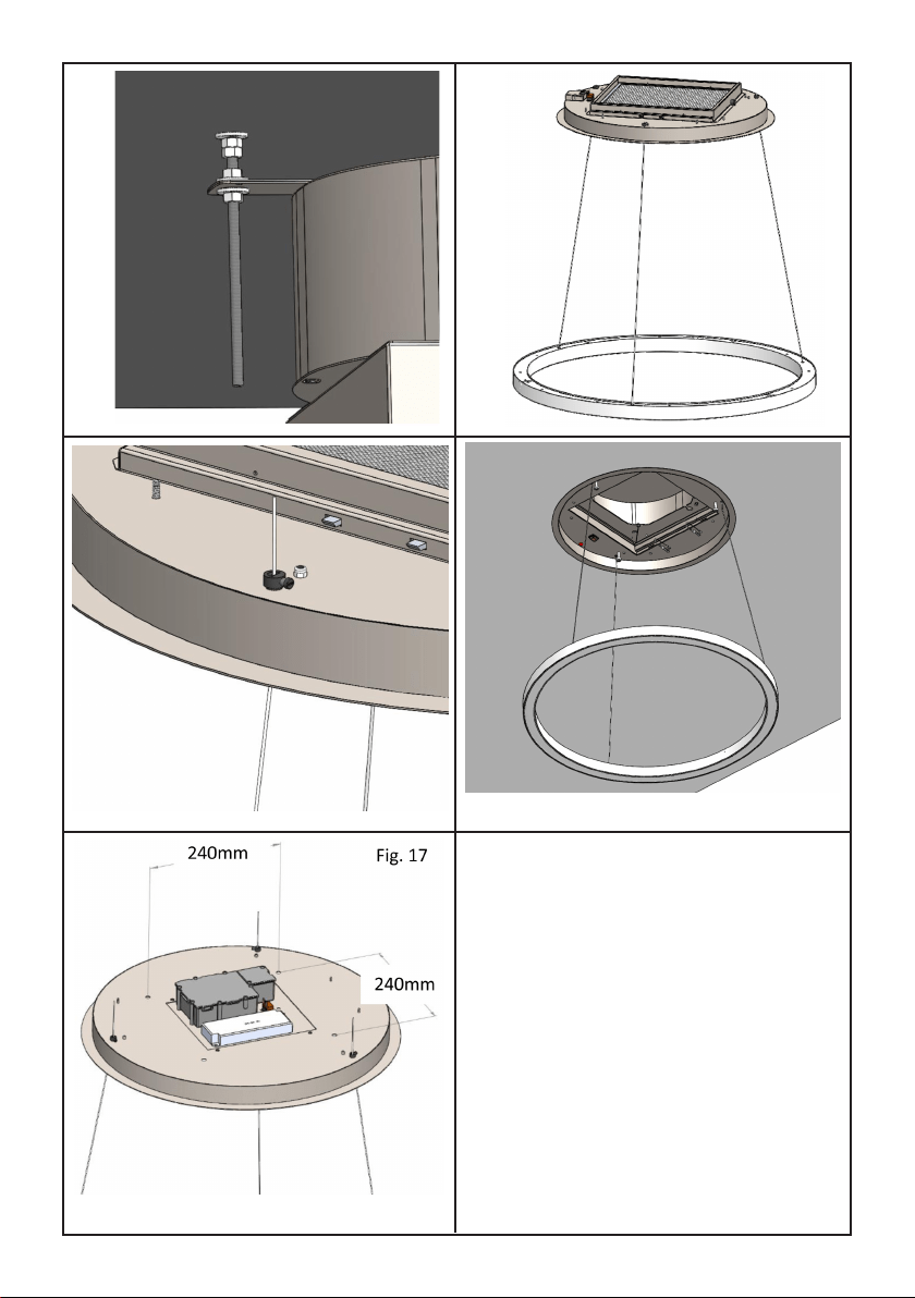
Estrarre il prodotto dalla confezione e collocarlo
su una supercie adatta: suggeriamo di usare un
materiale morbido, come una spugna o un panno.
Aprire il pannello come mostrato in Fig. 1 e de-
scritto nel paragrafo precedente, rimuovere il l-
tro antigrasso agendo nell’apposita maniglia.
Utilizzando un utensile adeguato rimuovere le
otto viti di ssaggio della cornice esterna quindi
rimuoverla come da g. 11.
Scollegare anche il cavo at ed il cavo elettrico
del tasto reset.
Installare la parte superiore del prodotto nella
nicchia in cartongesso, occorre far coincidere le
tre asole con le barre letatte precedentemente
installate, come da g. 12.
Portare il prodotto a battuta delle rondelle posi-
zionate in precedenza.
Bloccare il prodotto mediante tre rondelle e tre
dadi forniti in dotazione. (g. 13)
Effettuare il collegamento della canalizzazione
uscita aria ed il collegamento alla rete elettrica.
Prelevare la plafoniera LED dall’imballaggio e far
passare i cavi elettricabili all’interno delle tre fo-
rature presenti nella cornice, (g. 14)
Regolare l’altezza desiderata della plafoniera
LED, rispetto al pavimento, agendo nel morsetto
di bloccaggio del cavo elettricabile come da g.
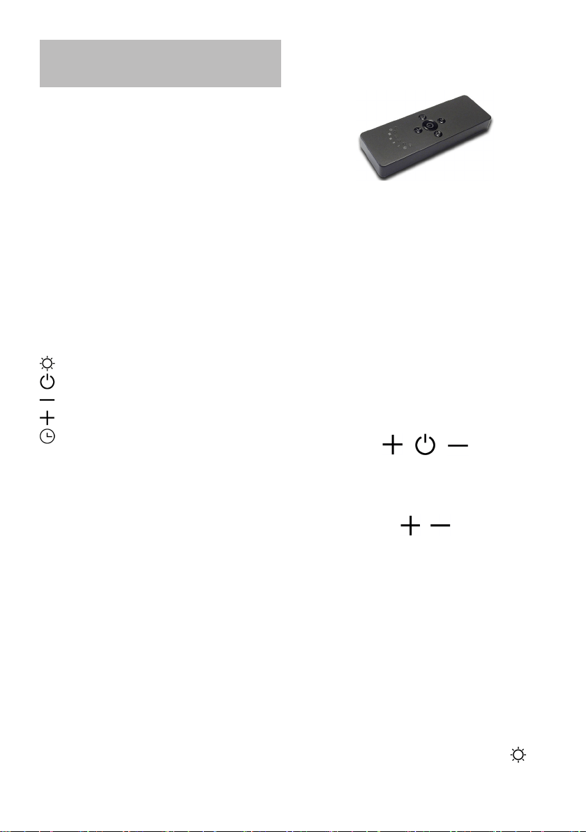
15.
Avvicinare la cornice alla nicchia del cartongesso
quindi ripristinare i collegamenti elettrici rimossi
in precedenza ed effettuare il collegamento elet-
trico della plafoniera LED, fare attenzione a non
confondere le polarità positivo, negativo e terra
segnalate dalle etichette nei cavi elettrici.
Bloccare la nicchia al prodotto precedentemente
ssato mediante le otto viti rimosse in preceden-
za, g. 16.
Ripristinare il ltro antigrasso ed il pannello in
metallo ssato con appositi magneti.

Per l’installazione del prodotto in versione lampa-
da è necessario creare un ribassamento in carton-
gesso, mantenendo almeno 100mm di distanza
tra lo stesso ed il softto solido.
Occorre realizzare un’apertura circolare nel car-
tongesso, delle dimensioni pari a: 510mm (g. 4)
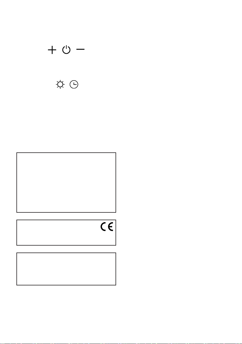
Realizzare una struttura in metallo oppure in legno
sulla quale ssare il prodotto, occorre considerare
le forature di ssaggio indicate in g. 17.
Oltre a quanto sopra indicato, procedere con l’in-
stallazione come per il prodotto cappa, indicato nel
capitolo precedente.
10
INSTALLAZIONE
VERSIONE LAMPADA
11
FUNZIONAMENTO
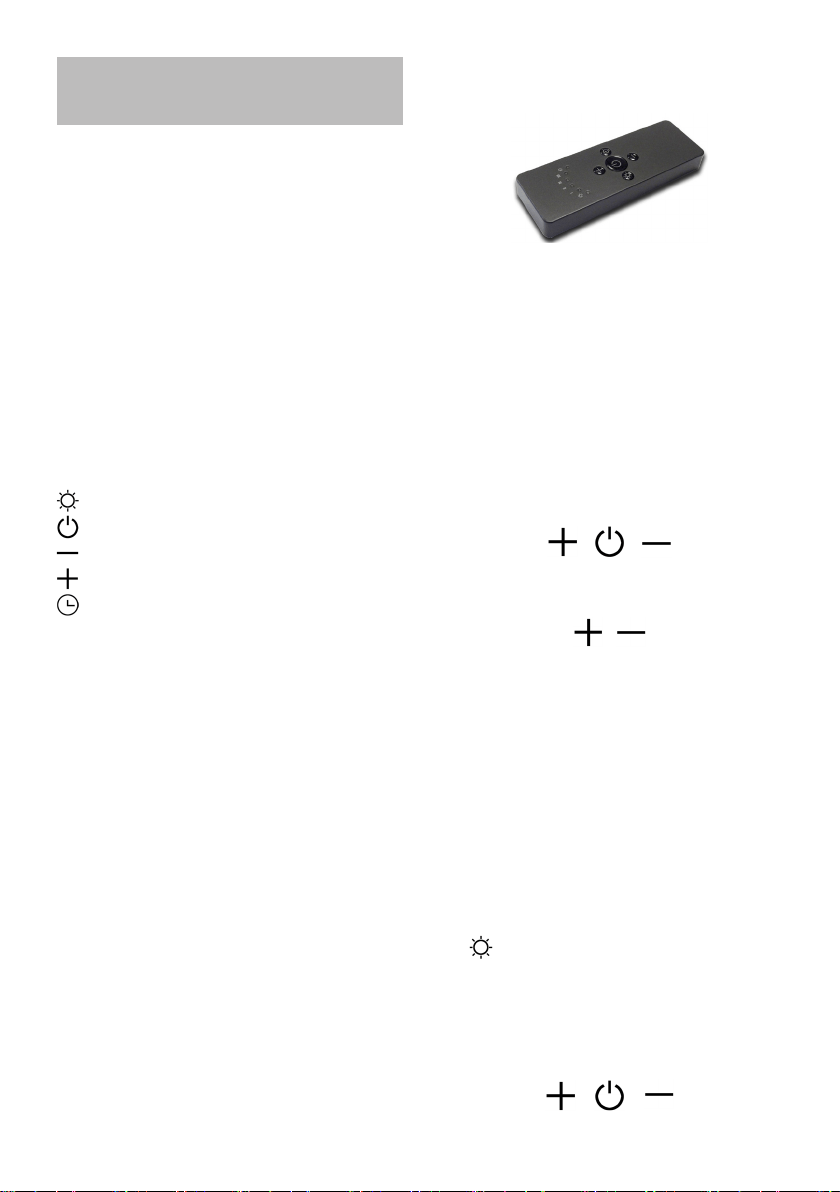
RADIOCOMANDO SERIE
RC001
Radiocomando per il comando a distanza di cap-
pe aspiranti.
CARATTERISTICHE TECNICHE
- Alimentazione pila alkalina: 12V mod. 27A
- Frequenza di lavoro: 433,92 Mhz
- Combinazioni: 32.768
- Consumo max.: 25 mA
- Temperatura d’esercizio: -20 ÷ + 55 °C
- Dimensioni: 130x45x15mm.
DESCRIZIONE DI FUNZIONAMENTO
Il trasmettitore è dotato di 5 tasti per la gestione
del funzionamento della cappa, come di seguito
specicato:
: interruttore ON/OFF luce.
: interruttore ON (1° velocità) OFF motore.
: diminuire velocità.
: aumentare velocità.
: temporizzatore 10 minuti.
FUNZIONE LUCI DIMMERABILE
TALE FUNZIONE PREVEDE LA DIMMERABILITA’
DELLE LUCI DAL 20% FINO AL 100% TRAMITE LA
PRESSIONE CONTINUATA DEL TASTO LUCE DEL
TELECOMANDO.
LE FUNZIONI SONO LE SEGUENTI:
- LUCE CAPPA SPENTA - PRESSIONE BREVE DEL
TASTO - ACCENZIONE LUCE AL 100%.
- LUCE ACCESA AL 100% - PRESSIONE BREVE DEL
TASTO - SPEGNIMENTO LUCE.
- LUCE ACCESA AL 100% - PRESSIONE CONTI-
NUATA DEL TASTO - DIMINUZIONE DELLA LU-
MINOSITÀ.
- RILASCIO DEL TASTO DURANTE LA DIMI-
NUZIONE O INCREMENTO - LA LUCE RIMANE
NELL’INTENSITÀ OTTENUTA.
- LUCE ACCESA DIMMERATA - NUOVA PRESSIO-
NE CONTINUATA DEL TASTO - INVERSIONE LU-
MINOSITA’ RISPETTO ALLA PRECEDENTE.
CONDIZIONE INIZIALE DI FUNZIONAMENTO
Il radiocomando viene fornito dal costruttore
pronto per l’uso, contenente già dei codici prede-
niti di Fabbrica.
MODALITÀ DI FUNZIONAMENTO
Congurazione standard:
La congurazione di fabbrica prevede che tut-
ti i sistemi “ cappa - radiocomando “ abbiano lo
stesso codice di trasmissione. Nel caso siano
installati due sistemi “ cappa - radiocomando “
nello stesso locale o nelle immediate vicinanze
i sistemi avendo lo stesso codice di trasmissione
potrebbero essere inuenzati quindi è necessario
cambiare il codice di un solo radiocomando.
Generazione di un nuovo codice trasmissio-
ne:
Il radiocomando viene fornito dalla fabbrica con
dei codici predeniti. Se si desidera una nuova
generazione di codici, occorre eseguire la proce-
dura nel seguente modo: premere contempora-
neamente i tasti:
in modo continuo per 2 secondi, nello stesso
istante si avrà l’accensione dei Led, successiva-
mente premere i tasti:
(entro 5 secondi), 3 lampeggi dei Led indicheran-
no che l’operazione è stata completata.
ATTENZIONE! Questa operazione cancella in
maniera denitiva i codici preesistenti.
Apprendimento del nuovo codice di trasmis-
sione:
Dopo aver cambiato il codice di trasmissione nel
radiocomando, occorre far apprendere alla cen-
trale elettronica della cappa aspirante il nuovo
codice nel seguente modo:
Premere il pulsante di spegnimento generale del-
la cappa, ripristinare l’alimentazione alla centrale
elettronica, da questo momento ci sono 15 se-
condi di tempo per premere il tasto Luce: per
far sì che la centrale si sincronizzi con il nuovo
codice.
Ripristino della congurazione di Fabbrica:
Se si desidera ripristinare la congurazione di
Fabbrica, occorre eseguire la procedura nel se-
guente modo: premere contemporaneamente i
tasti:
in modo continuo per 2 secondi, nello stesso
istante si avrà l’accensione dei Led, successiva-
mente premere i tasti:
(entro 5 secondi), 6 lampeggi dei Led indicheran-
no che l’operazione è stata completata.
ATTENZIONE! Questa operazione cancella in
maniera denitiva i codici preesistenti.
Tasto d’emergenza:
In caso di non funzionamento del radiocomando,
per lo spegnimento dell’apparecchiatura, interve-
nire sul tasto d’emergenza. Dopo eventuali ripa-
razioni, ripristinare il tasto d’emergenza.
ATTENZIONE
La batteria deve essere sostituita ogni anno
per garantire la portata ottimale del trasmet-
titore.
Per sostituire la batteria scarica rimuovere il
coperchio di plastica, togliere la batteria in uso
e inserirne una nuova rispettando la polarità
indicata nel contenitore.
La batteria usata deve essere smaltita negli
appositi raccoglitori.
Il prodotto
Radiocomando RC001
è conforme alle speciche della Direttiva
R&TTE 99/5/EC.
AVVERTENZE
Cambiamenti o modiche non espressamente
approvate dal detentore del certicato di com-
patibilità alle norme possono invalidare il di-
ritto dell’utente all’utilizzo dell’apparecchiatura
Rev. 0 26/08/14
TEMPORIZZAZIONI
Con l’entrata in vigore dal 1° Gennaio 2015 dei
nuovi regolamenti della Commissione Europea
EU65 “Energy label” e EU66 “ Ecodesign”, ab-
biamo reso conforme i prodotti in base ai requisiti
richiesti.
Tutti i modelli nelle versioni energy label dispon-
gono di una elettronica, con funzioni di temporiz-
zazione delle velocità di aspirazione, superiore a
650m³/h.
In effetti i modelli con motore a bordo, con porta-
ta massima superiore a 650m³/h, prevedono la
IV
a
velocità temporizzata dopo 5 minuti di funzio-
namento, Trascorsi i tempi di cui sopra il motore
di aspirazione passa alla III
a
velocità in maniera
automatica.
I prodotti in versione external motor, vengono
abbinati soltanto con motori remoti dove, come
per la versione con motore a bordo, vengono
temporizzate le velocità con portate superiori a
650m³/h. (Vedi istruzioni riportate nei motori re-
moti).
I motori remoti, che hanno una portata superiore
a 650m³/h sia alla IV
a
che alla IIIa velocità, vengo-
no automaticamente temporizzate come segue:
dalla IV
a
velocità, dopo 6 minuti di funzionamento
passa automaticamente alla II
a
velocità.
Se il prodotto viene impostato alla III
a
velocità,
passa automaticamente alla II
a
velocità dopo 7
minuti. Resta comunque possibile modicare le
velocità in uso.
Il prodotto in modalità stand-by ha un consumo
inferiore a 0.5W.
12
Il prodotto è dotato di un dispositivo elettronico
che permette lo spegnimento automatico dopo
quattro ore di funzionamento dall’ultima opera-
zione eseguita.

13
Una manutenzione accurata garantisce un buon
funzionamento e prestazioni durature.
Una speciale cura va rivolta al ltro antigrasso:
per accedere al ltro, procedere come descritto
nel Capitolo APERTURA DEL PANNELLO.
Rimuovere il ltro antigrasso, usando l’apposita
maniglia.
Per rimontare il ltro antigrasso dopo la pulizia,
eseguire la stessa operazione in ordine inverso.
Per rimuovere il ltro al carbone, se installato, se-
guire gli stessi passi del ltro antigrasso.
Il ltro a carbone si trova immediatamente sopra
il ltro antigrasso.
L’acqua tiepida e detergenti neutri sono racco-
mandati per pulire l’apparecchio, mentre devono
essere evitati prodotti abrasivi.
Se il cavo di alimentazione è danneggiato, deve
essere sostituito da una persona qualicata.
MANUTENZIONE

INDEX
Warnings
Usage system
Installation of the hood version
Installation lamp version
Functioning
Maintenance
GB
14

In case of installation with gas
cooker hob, the minimum di-
stance between the lower part
of the hood and the stove must
be at least 650 mm.
During the electrical connec-
tion, make sure that the po-
wer socket is equipped with a
ground connection and check
that the voltage values corre-
spond to those indicated on
the plate inside the appliance.
Before any cleaning or main-
tenance work, the appliance
must be disconnected from the
power grid.
If the appliance is not equip-
ped with a non exible cable
or plug, or other device to en-
sure Omni polar disconnection
from the grid, with an opening
distance of at least 3 mm, then
these gird disconnectors must
be provided in the xed instal-
lation.
If the appliance is equipped
with a power cable and a plug,
it must be placed so that the
plug is accessible.
Avoid the use materials that
cause ames in the immediate
proximity of the appliance. In
the case of fried food, please
pay particular attention to re
hazard that constitute oil and
grease. The oil already used is
particularly dangerous for its
ammability. Do not use unco-
vered electric grids.
WARNINGS
In order to install the product,
two people are required.
Children and inexperienced or
disabled people may use the
appliance only under the su-
pervision of adults.
The air sucked can’t be conve-
yed through or into a duct used
to let out fumes from applian-
ces fed by energy.(eg. centra-
lized heating, radiators, water-
heaters, etc.).
To evacuate the air outlet, ple-
ase comply with the pertaining
rules given by competent au-
thorities.
Provide for an adequate room
ventilation when hoods and
appliances powered by energy
(gas, oil, coal stoves, etc.), are
used in the following ways at
the same time.
The hood may create a nega-
tive pressure in the room eva-
cuating the air.
The negative pressure in the
room must not exceed 0.04
mbar, avoiding the suction of
exhaust gases from the heat
source.
Therefore, the room must be
equipped with air intakes that
supply a constant ow of fresh
air.
15

USAGE SYSTEM
PANEL OPENING
It is possible to open the grease lter cover panel
pulling it gently, as shown in g. 1.
The panel is xed with three magnets, there
are two safety cables to release in order to re-
move the panel from the product.
For the proper functioning, it is recommended to
install the product at a maximum distance of 2000
- 2100 mm, from the oor level.
Before proceeding with the installation of the ap-
pliance, check that all the components are not
damaged otherwise, please contact the dealer
and do not continue with the installation.
Use an air outlet pipe with a maximum length of
no more than 5 metres.
- Reduce the number of curves in the duct as
each curve reduces the suction efciency equi-
valent to 1 linear meter. (E.g.: if 2 90° curves are
used, the length of the duct should not exceed 3
meters in length).
- Avoid drastic changes of direction.
- Use a duct with a diameter of 150mm constant
over the entire length.
- Use a duct of recognized and approved mate-
rial.
To avoid a possible re risk,
follow the instructions given
for cleaning the grease lters
and removing any grease de-
posits on the unit.
16

17
HOOD VERSION
INSTALLATION
For the installation of this product it is necessary
to create a plasterboard lowering, keeping at le-
ast 220mm distance between the same and the
solid ceiling.
The material supplied with the product allows it
to be installed on lowerings ranging from 220mm
(g. 2) to 300mm (g. 3) of distance between the
plasterboard and the solid ceiling.
It is necessary to make a circular opening in the
plasterboard, with a diameter equal to: 510mm
(g. 4)
Using a level and a pencil, bring the four ends of
the holes created in the plasterboard directly into
the solid ceiling, see g. 5, then draw perpendi-
cular lines as shown in g. 6, in order to nd the
center of the hole.
Position the drilling template supplied, aligning
the centre of the template with the centre of the
axes previously drawn (g. 7). Using a pencil, tra-
ce the three holes to be made in the solid ceiling.
Before tracing the holes you can rotate the
drilling template in order to orient the air out-
let of the fan in the desired direction. The po-
sition of the air outlet of the fan is indicated in the
drilling template.
Perform the three holes in the solid ceiling using
a helical tip with a diameter of 8mm.
Insert the metric inserts supplied into the holes
made.
Insert the threaded bars into the metric inserts
previously installed.
Screw the threaded bars using two nuts, as
shown in g. 8, act in the nut below to screw the
threaded bar.
Insert an additional nut, a metal washer and a
plastic locking washer as shown in gure 9. For
correct installation, position the metal washer
200mm high from the bottom surface of the
plasterboard, see gure 10.
Remove the product from its packaging and place
it on a suitable surface: we suggest using a soft
material, such as a sponge or a cloth.
Open the panel as shown in Fig. 1 and described
in the previous paragraph, remove the grease lter
using the handle.
Using a suitable tool, remove the eight screws
securing the outer frame and then remove it as
shown in Fig. 11.
Also disconnect the at cable and the electrical ca-
ble of the reset button.
Install the upper part of the product in the plaster-
board niche, the three slots must coincide with the
threaded rods previously installed, as shown in g.
12.
Bring the product to a stop with the washers pre-
viously positioned.
Secure the product with three washers and three
nuts supplied. (g. 13)
Connect the air outlet duct and the power supply.
Remove the LED ceiling light from its packaging
and run the cables through the three holes in the
frame (g. 14).
Adjust the desired height of the LED ceiling light to
the oor using the cable clamp as shown in g. 15.
Move the frame closer to the plasterboard niche,
then restore the previously removed electrical con-
nections and make the electrical connection of the
LED ceiling light, taking care not to confuse the
positive, negative and ground polarities indicated
by the labels in the electrical cables.
Lock the niche to the product previously xed with
the eight screws previously removed, g. 16.
Restore the grease lter and the metal panel xed
with special magnets.

For the installation of the product in lamp version it
is necessary to create a plasterboard lowering, ke-
eping at least 100mm distance between the same
and the solid ceiling.
A circular opening must be made in the plasterbo-
ard, with dimensions equal to: 510mm (g. 4)
Make a metal or wooden structure on which to x
the product; consider the xing holes indicated in
g. 17.
In addition to what is indicated above, proceed
with the installation as for the hood product, indi-
cated in the previous chapter.
18
LAMP VERSION
INSTALLATION
19
RC001
RADIO CONTROL
Radio control used for the remote operation of
ducted cooker hoods.
TECHNICAL DATA
- Alkaline battery powered: 12 V mod. 27A
- Operating frequency: 433.92 Mhz
- Combinations: 32.768
- Max. consumption: 25 mA
- Operating temperature: -20 ÷ + 55 °C
- Dimensions: 130x45x15 mm.
OPERATING DESCRIPTION
The transmitter is equipped with 5 buttons for co-
oker hood management, as specied below:
: Light ON/OFF command.
: Motor ON (speed level 1) / OFF command.
: Reduce speed.
: Increase speed.
: 10-minute timer.
DIMMABLE LIGHTS FUNCTION
THIS FUNCTION PROVIDES FOR LIGHTS DIM-
MABILITY, RANGING FROM 20% TO 100% , BY
CONTINUOUSLY PRESSING THE LIGHT KEY
ON THE REMOTE CONTROL.
FUNCTIONS ARE THE FOLLOWING:
- HOOD LIGHT OFF - SHORTLY PRESS THE
KEY - LIGHT ON AT 100%.
- LIGHT ON AT 100% - SHORTLY PRESS THE
KEY - LIGHT OFF.
- LIGHT ON AT 100% - CONTINOUSLY PRESS
THE KEY - BRIGHTNESS REDUCTION.
- RELEASING THE KEY DURING REDUCTION
OR INCREASE - LIGHT KEEPS THE LUMINOUS
INTENSITY REACHED.
- LIGHT ON - DIMMED - CONTINOUSLY
PRESS THE KEY - BRIGHTNESS IS INVERTED
IF COMPARED TO THE PREVIOUS FUNCTION.
INITIAL OPERATING CONDITION
The manufacturer supplies the radio control unit
ready to be used with codes preset in the Factory
OPERATION MODE
Standard conguration:
Standard conguration requires all “cooker hoods
– radio control - system” to be provided with the
same transmission code. In the event two cooker
hoods – radio control system are installed in the
same room or nearby, each system may affect
the operation of the another. Therefore, the code
of one radio control system must be changed.
Generating a new transmission code:
The radio control system is provided with preset
codes. Should new codes be required, proceed
as follows: Press simultaneously buttons:
for two seconds. When Leds light on, press but-
tons:
(within 5 seconds). Leds ashing 3 times indicate
the procedure is completed.
WARNING! This operation deletes permanen-
tly the preset codes.
Learning the new transmission code:
Once the transmission code is changed in the ra-
dio control unit, the electronic central unit of the
cooker hood must be made to set the new code
in the fol- lowing way:
Press the main power-off button of the hood and
then restore power to the electronic control unit.
Within the next 15 seconds, press the Liight But-
ton to synchronise the central unit with the
code.
Reset of the Factory conguration:
To restore the Factory conguration, follow the
procedure described below: press simultaneou-
sly buttons:
WORKING
20
for 2 seconds. When Leds light on, press buttons:
(within 5 seconds). Leds ashing 6 times indicate
the procedure is completed.
WARNING! This operation deletes permanen-
tly the preset codes.
Emergency button:
In the event that the radio control does not work,
use the emergency button to switch the appliance
off. After any necessary repairs have been perfor-
med, reset the emergency button.
WARNING
The battery should be replaced every year to
guarantee the optimal range of the transmitter.
To replace the exhausted battery, take the pla-
stic lid off, remove the battery and replace it
with a new one, observing the correct battery
polarities.
Used batteries should be discarded in special
collection bins.
The below product:
RC001 Radiio Controll
complies with the specications set out in the
R&TTE Directive 99/5/EC.
WARNING
Any adjustments or modications which have
not been expressly approved by the holder of
the legal conformity certicate may invalidate
the user’s rights relating to the operation of
the device.
Rev. 0 26/08/14
The products are endowed with an electronic de-
vice which allows the automatic switching off after
4 hours working from the last operation.
TIMING
As a result of the new EU65 “Energy label” and
EU66 “ Ecodesign” regulations issued by the Eu-
ropean Commission, which came into force as
from January 1st, 2015 , our products have been
adapted to comply with these new requirements.
All of the models complying with the energy label
requirements, are equipped with new electronics
including a timer device for suction speeds con-
trol, when the air capacity exceeds 650m³/h.
Internal motor models, with maximum air capa-
city higher than 650m³/h, are equipped with a
timer device that automatically switches the suc-
tion speed from 4th to 3rd speed, after 5 minutes
operation.
External motor models are equipped with remote
motors that , as for internal motor versions, inclu-
de a timer device that switches down the suction
speed when it exceeds 650 mᵌ/h. (See External
Motors Instructions).
Remote motors, whose air capacity exceeds
650m³/h at both 4th and 3rd speed , will have the
following by default timer control functions: The
suction speed is automatically switched from 4th
to 2nd speed, after 6 minutes operation.
If the appliance is working at 3rd speed, it is auto-
matically switched to 2nd speed, after 7 minutes
operation. Operation speeds can also be chan-
ged during operation.
The energy consumption of the appliance in
stand – by mode is lower than 0.5W.

Careful maintenance ensures smooth operation
and long-lasting performance.
Special care must be taken with the grease lter:
To access the lter, proceed as follows:
In the Chapter → OPENING THE PANEL.
Remove the grease lter using the special han-
dle.
To replace the grease lter after cleaning, full
the same operation in reverse order.
To remove the carbon lter, if installed, follow the
same steps as the grease lter.
The carbon lter is located immediately above
the grease lter.
Warm water and neutral detergents are recom-
mended to clean up the appliance, while abrasive
products should be avoided.
If the power cord is damaged, a qualied person
must replace it.
It is possible to open the grease lter cover panel
pulling it as shown in g. 1.
The panel is xed with three magnets, there are
two safety cables to be released to remove the
panel from the product.
For proper operation, it is recommended to install
the product at a maximum distance, from the oor
level, of 2000 - 2100 mm.
MAINTENANCE
21

22

23

90009730000 - 03/19
