INFORMAZIONI COMMERCIALI PER I CONSUMATORI
COMMERCIAL INFORMATION FOR THE CONSUMER
INFORMATIONS COMMERCIALES POUR LE CLIENT
INFORMACIONES COMERCIALES PARA EL CLIENTE
HANDELSINFORMATIONEN FÜR DEN KUNDEN
COMMERCIËLE INFORMATIES VOOR DE KLANT
INFORMAZIONI TECNICHE
TECHNICAL INFORMATION
INFORMATION TECHNIQUES
INFORMACIONES TÉCNICAS
TECHNISCHE INFORMATIONEN
TECHNISCHE INFORMATIES
TYPE: FSLA
ISTRUZIONI PER INSTALLAZIONE USO E MANUTENZIONE
INSTALLATION, USE AND MAINTENANCE INSTRUCTION
INSTRUCTIONS D’UTILISATION ET AVIS DE MONTAGE
INSTRUCCIONES DE USO Y DE MONTAJE
BEDIENUNGSANLEITUNG MIT MONTAGEANWEISUNGEN
GEBRUIKSAANWIJZIGING
IT
GB
F
E
D
NL
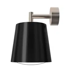
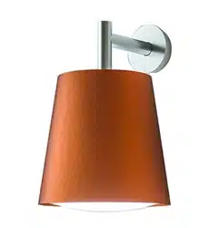
APPLIQUE
SLT105

2
3
Il simbolo sul prodotto o sulla confezione indica che il prodotto non deve essere
considerato come un normale riuto domestico, ma deve essere portato nel punto
di raccolta appropriato per il riciclaggio di apparecchiature elettriche ed elettroni-
che. Provvedendo a smaltire questo prodotto in modo appropriato, si contribuisce
a evitare potenziali conseguenze negative per l’ambiente e per la salute, che po-
trebbero derivare da uno smaltimento inadeguato del prodotto. Per informazio-
ni più dettagliate sul riciclaggio di questo prodotto, contattare l’ucio comuna-
le, il servizio locale di smaltimento riuti o il negozio in cui è stato acquistato il
prodotto. Questo elettrodomestico è marcato conformemente alla Direttiva Eu-
ropea 2012/19/EC sui riuti da apparecchiature elettriche ed elettroniche (WEEE).
IT
The symbol on the product or on its packaging indicates that this product may not be
treated as household waste. Instead it shall be handed over to the applicable collection
point for the recycling of electrical and electronic equipment. By ensuring this product
is disposed of correctly, you will help prevent potential negative consequences for the
environment and human health, which could otherwise be caused by inappropriate
waste handling of this product. For more detailed information about recycling of this
product, please contact your local city oce, your household waste disposal service or
the shop where you purchased the product. This appliance is marked according to the
European directive 2012/19/EC on waste electrical and electronic equipment (WEEE).
GB
Le symbole sur le produit ou son emballage indique que ce produit ne peut être traité
comme déchet ménager. Il doit plutôt être remis au point de ramassage concerné, se
chargeant du recyclage du matériel électrique et électronique. En vous assurant que
ce produit est éliminé correctement, vous favorisez la prévention des conséquences
négatives pour l’environnement et la santé humaine qui, sinon, seraient le résultat
d’un traitement inapproprié des déchets de ce produit. Pour obtenir plus de détails sur
le recyclage de ce produit, veuillez prendre contact avec le bureau municipal de votre
région, votre service d’élimination des déchets ménagers ou le magasin où vous avez
acheté le produit. Cet appareil est commercialisé en accord avec la directive européen-
ne 2012/19/EC sur les dèchets del équipments èlectriques et èlctroniques (WEEE).
F
El símbolo en el producto o en su embalaje indica que este producto no se pue-
de tratar como desperdicios normales del hogar. Este producto se debe entregar al
punto de recolección de equipos eléctricos y electrónicos para reciclaje. Al asegurar-
se de que este producto se deseche correctamente, usted ayudará a evitar posibles
consecuencias negativas para el ambiente y la salud pública, lo cual podría ocurrir
si este producto no se manipula de forma adecuada. Para obtener información más
detallada sobre el reciclaje de este producto, póngase en contacto con la admini-
stración de su ciudad, con su servicio de desechos del hogar o con la tienda donde
compró el producto. Este electrodomestico està marcado conforme a la directiva Eu-
ropea 2012/19/EC sobre los residuos de aparatos elèctricos y electrònicos (WEEE).
E
4
Das Symbol auf dem Produkt oder seiner Verpackung weist darauf hin, dass dieses
Produkt nicht als normaler Haushaltsabfall zu behandeln ist, sondern an einem Sam-
melpunkt für das Recycling von elektrischen und elektronischen Geräten abgegeben
werden muss. Durch Ihren Beitrag zum korrekten Entsorgen dieses Produkts schützen
Sie die Umwelt und die Gesundheit Ihrer Mitmenschen. Umwelt und Gesundheit wer-
den durch falsches Entsorgen gefährdet. Weitere Informationen über das Recycling
dieses Produkts erhalten Sie von Ihrem Rathaus, Ihrer Müllabfuhr oder dem Geschäft,
in dem Sie das Produkt gekauft haben. Dieses Elektrohaushaltsgerät ist entspre-
chend der EU-Richtlinie 2012/19/EC Über Elektro- und Elektronik – Altgeräte (WEEE).
D
Het symbool op het product of op de verpakking wijst erop dat dit product niet
als huishoudafval mag worden behandeld. Het moet echter naar een plaats wor-
den gebracht waar elektrische en elektronische apparatuur wordt gerecycled. Als
u ervoor zorgt dat dit product op de correcte manier wordt verwijderd, voorkomt
u mogelijk voor mens en milieu negatieve gevolgen die zich zouden kunnen vo-
ordoen in geval van verkeerde afvalbehandeling. Voor meer details in verband
met het recyclen van dit product, neemt u het best contact op met de gemeente-
lijke instanties, het bedrijf of de dienst belast met de verwijdering van huishou-
dafval of de winkel waar u het product hebt gekocht. Dit apparrat voldoet aan de
Europese richtlijnen 2012/19/EC voor elektrische en elektronische afval (WEEE).
NL

INDICE
Avvertenze
Versioni d’uso
Installazione
Funzionamento
Manutenzione
5
IT

6
* Evitare l’uso di materiali che causano
ammate (ambè) nelle immediate vici-
nanze dell’apparecchio.
Nel caso di fritture fare particolarmente
attenzione al pericolo di incendio che co-
stituiscono olio e grassi.
Particolarmente pericoloso per la sua in-
ammabilità è l’olio già usato. Non usare
griglie elettriche scoperte.
Per evitare un possibile rischio d’incendio
attenersi alle istruzioni indicate per la pu-
lizia dei ltri antigrasso e la rimozione di
eventuali depositi di grasso sull’apparec-
chio.
* Per l’installazione del prodotto sono ri-
chieste due persone.
AVVERTENZE
La distanza minima tra la supercie del
piano di cottura e la parte inferiore della
cappa deve essere superiore a 65 cm.
* I bambini e le persone inesperte o i di-
sabili possono utilizzare l’apparecchio solo
sotto la supervisione di adulti.
* Prevedere un’adeguata aerazione del lo-
cale quando una cappa ed apparecchi ali-
mentati con energia diversa da quella elet-
trica (stufe a gas, ad olio, a carbone, ecc.),
vengono usati contemporaneamente.
La cappa aspirante evacuando l’aria po-
trebbe creare una pressione negativa nella
stanza.
La pressione negativa del locale non deve
superare i 0,04 mbar, evitando così il risuc-
chio dei gas di scarico della fonte di calo-
re. Pertanto bisogna attrezzare il locale con
delle prese d’aria che alimentino un usso
costante di aria fresca.
* Nell’operazione di collegamento elettri-
co assicurarsi che la presa di corrente sia
munita di collegamento a terra e vericare
che i valori di tensione corrispondono con
quelli indicati nella targhetta all’interno
dell’apparecchio.
* Prima di procedere a qualsiasi operazione
di pulizia o manutenzione è necessario to-
gliere l’apparecchio dalla rete elettrica.
Se l’apparecchio non è provvisto di cavo
essibile non separabile e di spina, o di al-
tro dispositivo che assicuri la omnipolare
disinserzione dalla rete, con una distanza
di apertura dei contatti di almeno 3 mm, in
tal caso tali dispositivi di separazione dalla
rete devono essere previsti nell’installazio-
ne ssa.
Se l’apparecchio è provvisto di cavo ali-
mentazione e di spina, deve essere posto
in modo che la spina sia accessibile.

7
VERSIONI D’USO
L’apparecchio deve essere utilizzato solo in
versione ltrante.
Nella versione ltrante l’aria ed i vapori con-
vogliati dall’apparecchio, vengono depurati
da un ltro antigrasso, da un ltro al carbone
e rimessi in circolazione nell’ambiente.
INSTALLAZIONE
Vericare che l’imballo sia integro e all’inter-
no tutti i componenti siano integri, in caso
contrario contattare il rivenditore e non pro-
seguire con l’installazione.
La ditta produttrice non risponde per dan-
ni causati durante la movimentazione e
l’installazione del prodotto.
Prima di procedere all’installazione legge-
re attentamente tutte le istruzioni di se-
guito riportate.
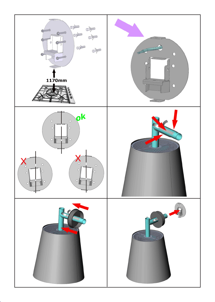
Prelevare dall’imballaggio la staa di sostegno
a parete ed installarla, mediante le viti ed i tas-
selli forniti in dotazione, come da gura 1. E’
possibile utilizzare la stessa staa come dima
per disegnare le forature da fare alla parete.
Attenzione: Prima di ssare la staa occorre
fare attenzione alle seguenti indicazioni:
1- il cavo alimentazione deve fuoriuscire dal
foro superiore della staa, come da g. 2;
2- La staa deve essere installata perfet-
tamente in asse con il piano del pavimento
come da gura 3;
3 - La parete su cui viene installato il prodot-
to deve sucientemente robusta, considera-
re che il prodotto ha un peso di circa…… KG
Prelevare il prodotto dall’imballaggio, pro-
teggendo il tubo di installazione con del na-
stro adesivo di carta, come da gura 4.
Inserire la cover della piastra a parete, come
indicato in gura 5, facendo attenzione a non
danneggiare la nitura del tubo, protetto con
il nastro adesivo di carta, come descritto nel
punto precedente.
Installare il prodotto alla staa a parete, pre-
cedentemente installata, inserendo il tubo di
installazione nell’apposita sede della staa,
vedi g. 6.
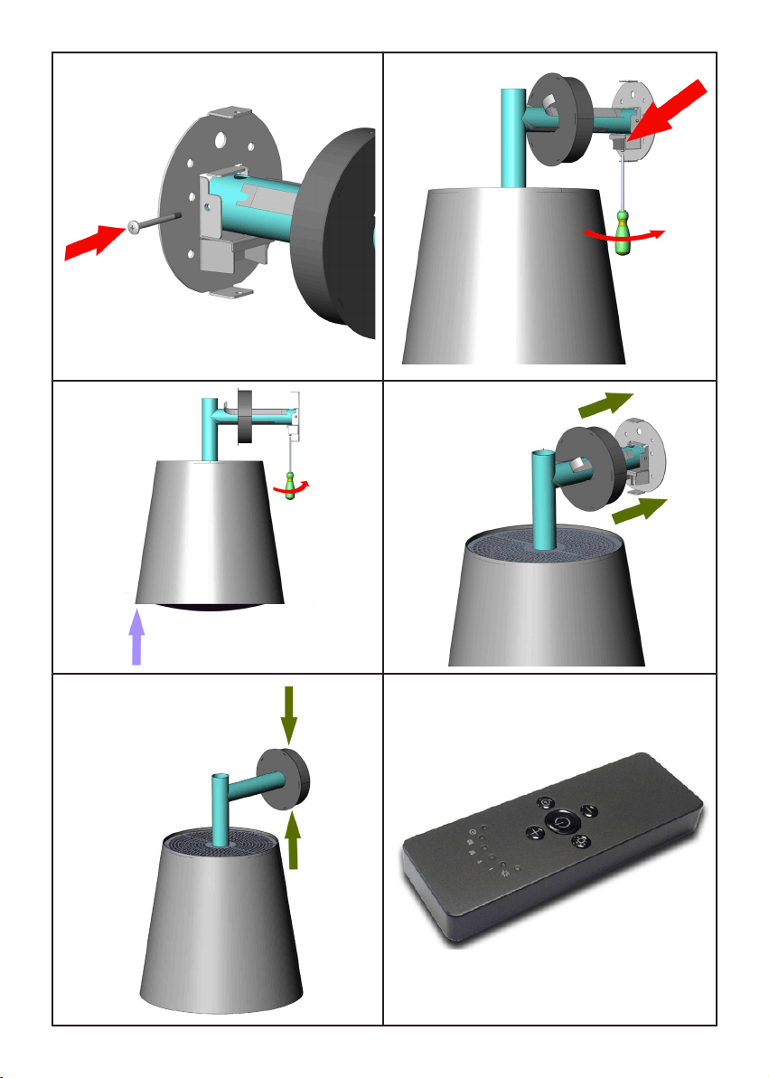
Bloccare il prodotto utilizzando la vite in do-
tazione, inserendola come da g. 7.
Fissare completamente mediante il dado M6,
fornito in dotazione.
Nel caso in cui il prodotto non risulti perfet-
tamente perpendicolare con il piano del pa-
vimento, è possibile eettuare una ulteriore
regolazione avvitando la vite indicata in gu-
ra 8, per allontanare la parte bassa del pro-
dotto dalla parete su cui è installato (g.9).
Mentre viene avvitata la vite (g.8), spingere
la parte bassa del prodotto dal basso verso
l’alto per facilitare la regolazione.
Eettuare il collegamento elettrico del pro-
dotto. (g. 15)
Posizionare la cover di copertura nella piastra
a parete (g. 10), quindi ssarla con le due
viti fornite in dotazione (g.11).
8
FUNZIONAMENTO
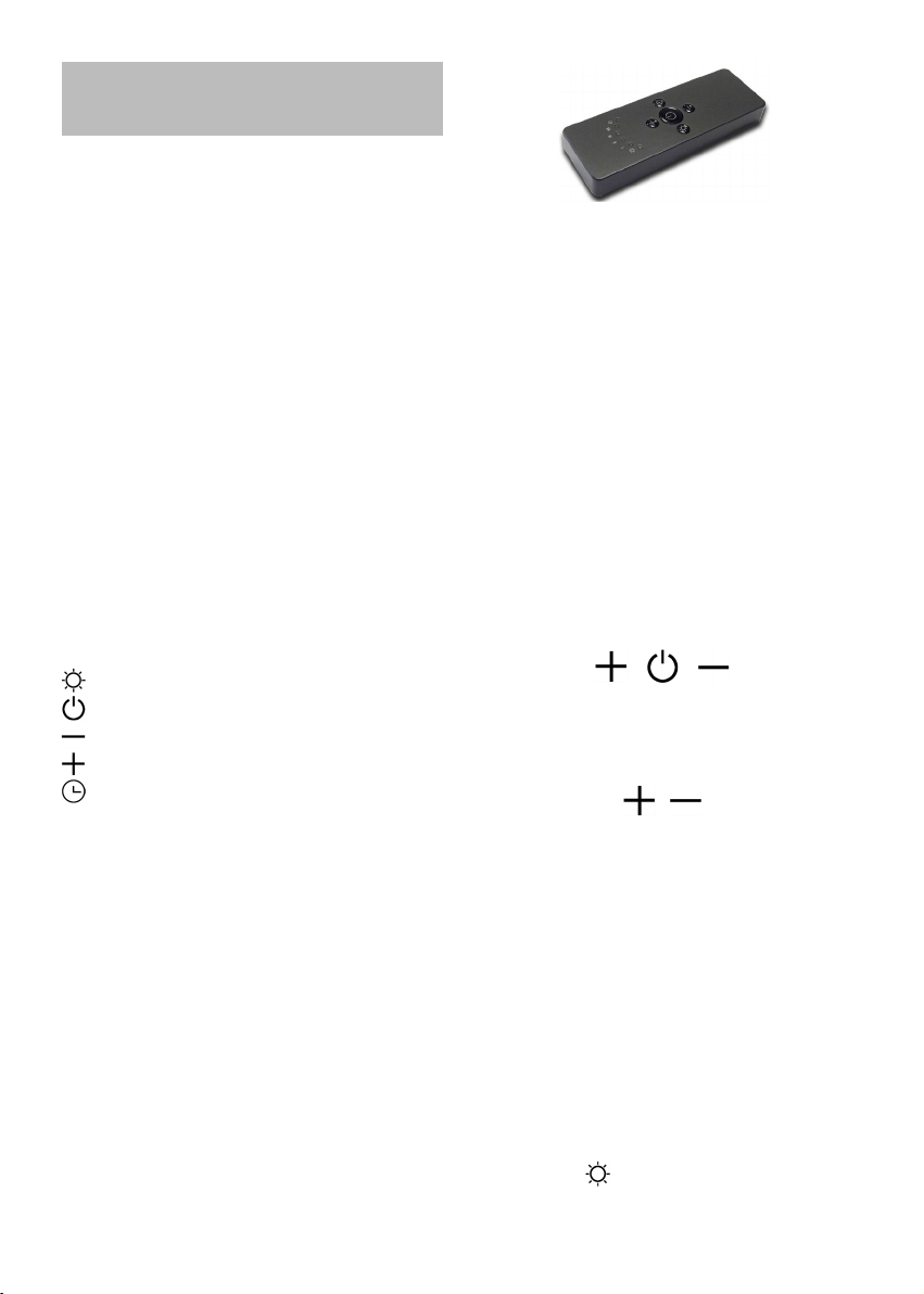
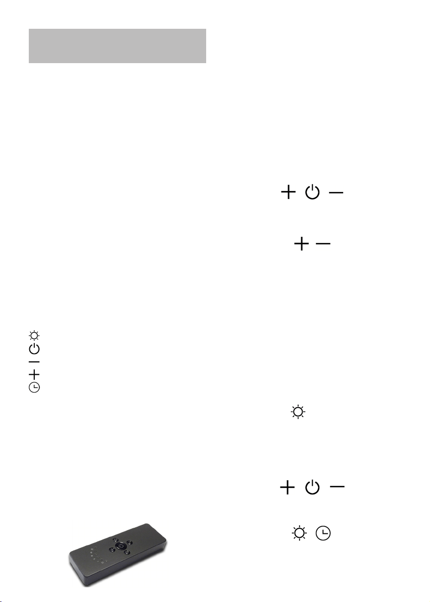
Telecomando (Fig. 12)
Alla prima accensione mantenere premuto il
tasto luce per 5 secondi.
RADIOCOMANDO SERIE
RC001
Radiocomando per il comando a distanza di
cappe aspiranti.
CARATTERISTIICHE TECNICHE
- Alimentazione pila alkalina: 12V mod.23A
- Frequenza di lavoro: 433,92 Mhz
- Combinazioni: 32.768
- Consumo max.: 25 mA
- Temperatura d’esercizio: -20 ÷ + 55 °C
- Dimensioni: 120x45x15mm.
DESCRIZIONE DI FUNZIONAMENTO
Il trasmettitore è dotato di 5 tasti per la ge-
stione del funzionamento della cappa, come
di seguito specicato:
: interruttore ON/OFF luce.
: interruttore ON (1° velocità) OFF motore.
: diminuire velocità.
: aumentare velocità.
: temporizzatore 10 minuti.
La velocità di aspirazione impostata viene
indicata mediante il led presente nel canale
perimetrale di aspirazione.
Ad ogni colore generato dal led, corrisponde
una determinata velocità come indicato sotto:
Prima velocità colore BIANCO
Seconda velocità colore AZZURRO
Terza velocità colore BLU
Quarta velocità colore ROSSO
CONDIZIONE INIZIALE DI FUNZIONAMENTO
Il radiocomando viene fornito dal costrutto-
re pronto per l’uso, contenente già dei codici
predeniti di Fabbrica.
MODALITÀ DI FUNZIONAMENTO
Congurazione standard:
La congurazione di fabbrica prevede che
tutti i sistemi “ cappa - radiocomando “ ab-
biano lo stesso codice di trasmissione. Nel
caso siano installati due sistemi “ cappa - ra-
diocomando “ nello stesso locale o nelle im-
mediate vicinanze i sistemi avendo lo stesso
codice di trasmissione potrebbero essere in-
uenzati quindi è necessario cambiare il co-
dice di un solo radiocomando.
Generazione di un nuovo codice trasmis-
sione:
Il radiocomando viene fornito dalla fabbrica
con dei codici predeniti. Se si desidera una
nuova generazione di codici, occorre esegui-
re la procedura nel seguente modo: premere
contemporaneamente i tasti:
in modo continuo per 2 secondi, nello stesso
istante si avrà l’accensione dei Led, successi-
vamente premere i tasti:
(entro 5 secondi), 3 lampeggi dei Led indi-
cheranno che l’operazione è stata completa-
ta.
ATTENZIONE! Questa operazione cancella
in maniera denitiva i codici preesistenti.
Apprendimento del nuovo codice di trasmis-
sione: Dopo aver cambiato il codice di tra-
smissione nel radiocomando, occorre far ap-
prendere alla centrale elettronica della cappa
aspirante il nuovo codice nel seguente modo:
Premere il pulsante di spegnimento gene-
rale della cappa, ripristinare l’alimentazione
alla centrale elettronica, da questo momento
ci sono 15 secondi di tempo per premere il
tasto Luce: per far sì che la centrale si
sincronizzi con il nuovo codice.
Il prodotto è dotato di un dispositivo elet-
tronico che permette lo spegnimento auto-
matico dopo quattro ore di funzionamento
dall’ultima operazione eseguita.
TEMPORIZZAZIONI
Con l’entrata in vigore dal 1° Gennaio 2015
dei nuovi regolamenti della Commissione
Europea EU65 “Energy label” e EU66 “ Eco-
design”, abbiamo reso conforme i prodotti in
base ai requisiti richiesti.
Tutti i modelli nelle versioni energy label di-
spongono di una elettronica, con funzioni di
temporizzazione delle velocità di aspirazio-
ne, superiore a 650m³/h.
In eetti i modelli con motore a bordo, con
portata massima superiore a 650m³/h, pre-
vedono la IVa velocità temporizzata dopo 5
minuti di funzionamento, Trascorsi i tempi di
cui sopra il motore di aspirazione passa alla
IIIa velocità in maniera automatica.
I prodotti in versione external motor, vengo-
no abbinati soltanto con motori remoti dove,
come per la versione con motore a bordo,
vengono temporizzate le velocità con portate
superiori a 650m³/h. (Vedi istruzioni riporta-
te nei motori remoti).
I motori remoti, che hanno una portata supe-
riore a 650m³/h sia alla IVa che alla IIIa velo-
cità, vengono automaticamente temporizzate
come segue: dalla IVa velocità, dopo 6 minuti
di funzionamento passa automaticamente
alla II velocità.
Se il prodotto viene impostato alla IIIa velo-
cità, passa automaticamente alla II velocità
dopo 7 minuti. Resta comunque possibile
modicare le velocità in uso.
Il prodotto in modalità stand-by ha un con-
sumo inferiore a 0.5W.
9
Ripristino della congurazione di Fabbrica:
Se si desidera ripristinare la congurazione
di Fabbrica, occorre eseguire la procedura nel
seguente modo: premere contemporanea-
mente i tasti:
in modo continuo per 2 secondi, nello stesso
istante si avrà l’accensione dei Led, successi-
vamente premere i tasti:
(entro 5 secondi), 6 lampeggi dei Led indi-
cheranno che l’operazione è stata completa-
ta.
ATTENZIONE! Questa operazione cancella
in maniera denitiva i codici preesistenti.
Tasto d’emergenza:
In caso di non funzionamento del radioco-
mando, per lo spegnimento dell’apparec-
chiatura, intervenire sul tasto d’emergenza.
Dopo eventuali riparazioni, ripristi- nare il
tasto d’emergenza.
ATTENZIONE
La batteria deve essere sostituita ogni
anno per garantire la portata ottimale del
trasmettitore.
Per sostituire la batteria scarica rimuovere
il coperchio di plastica, togliere la batteria
in uso e inserirne una nuova rispettando la
polarità indicata nel contenitore.
La batteria usata deve essere smaltita ne-
gli appositi raccoglitori.
Il prodotto
Radiocomando RC001
è conforme alle speciche della Direttiva
R&TTE 99/5/EC.
AVVERTENZE
Cambiamenti o modiche non espressa-
mente approvate dal detentore del certi-
cato di compatibilità alle norme possono
invalidare il diritto dell’utente all’utilizzo
dell’apparecchiatura
Rev. 0 26/08/14

Un’accurata manutenzione garantisce un
buon funzionamento ed un buon rendimento
nel tempo.
* Una cura particolare va rivolta al ltro an-
tigrasso.
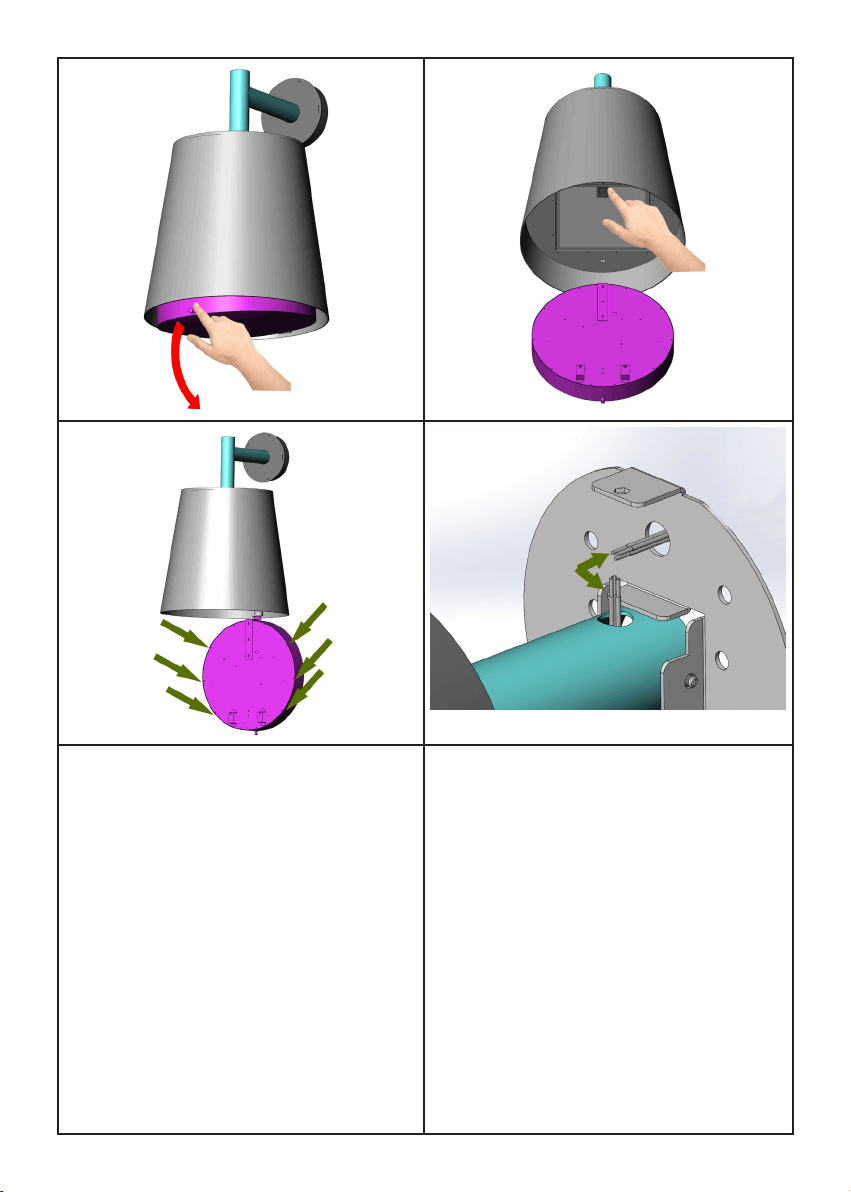
Il ltro antigrasso si rimuove aprendo il pan-
nello luce tirandolo verso il basso mediante
l’apposito pannello (g. 13).
Rimuovere il ltro antigrasso agendo sull’ap-
posita maniglia, come da g. 14. Il ltro car-
bone, è posizionato immediatamente dietro
al ltro antigrasso ed è possibile rimuoverlo
in maniera analoga.
La sostituzione del ltro al carbone avviene
in rapporto all’uso, almeno una volta ogni sei
mesi.
Per la pulizia dell’apparecchio stesso viene
consigliato l’uso di acqua tiepida e detersivo
neutro, evitando l’uso di prodotti contenenti
abrasivi.
La sostituzione del cavo alimentazione deve
essere eseguita esclusivamente da personale
autorizzato.
Ogni intervento per la sostituzione dei com-
ponenti elettrici dovrà essere eettuato da
personale tecnico specializzato.
10
MANUTENZIONE

CONTENTS
Warnings
Uses
Installation
Working
Maintenance
12
GB

13
In order to avoid possible re risk, all in-
structions for grease-lter cleaning and for
removing eventual grease deposits should
be strictly followed.
* Two persons are needed for the installa-
tion of this product.
WARNINGS
The cooker surface and the inferior part of
the cooker hood must be at a minimum di-
stance of 65 cm.
* The appliance is not intended for use by
young children or inrm persons without
supervision. Young children should be su-
pervised to ensure they do not play with the
appliance.
*The cooker hood, when evacuating the su-
cked air, could generate a negative pressu-
re in the room- which can’t exceed the limit
of 0.04 mbar, in order to avoid the suck of
exhausts deriving from the heat-source.
Therefore the room should be provided
with air-intakes to allow a constant ow of
fresh air.
* When performing the electrical connec-
tions on the appliance, please make sure
that them current-tap is provided with
earth connection and that voltage values
correspond to those indicated on the label
placed inside the appliance itself.
* Please disconnect the appliance from po-
wer mains, before carrying out any cleaning
or maintenance operation.
If the appliance is not equipped with a non-
separable exible cable and plug, or with
another device ensuring omnipolar discon-
nection from the mains, with an opening
distance between the contacts of at least 3
mm, then such disconnecting devices must
be provided in the xed installation.
If the appliance is equipped with a power
cord and a plug, it shall be placed in such
a way that the plug can be reached easily.
* The use of materials which can burst into
ames (ambé) should be avoided in close
proximity of the appliance.
When frying, please pay particular attention
to re risk due to oil and grease.
Being highly inammable, fried oil is espe-
cially dangerous. Do not use uncovered
electric grills.

14
USES
The appliance can be arranged only for lte-
ring performances. In its ltering version the
air and fumes conveyed by the appliance are
cleaned both by a grease lter and by an ac-
tive coal lter, and put again into circulation.
INSTALLATION
At tge beginning make sure that the packa-
ge is intact and all the parts are unbroken,
otherwise stop the installation and contact
the dealer. The manufacturer is not re-
sponsible for damages caused by material
handling or product installation.
Before installing the appliance read all
these instructions carefully.
Take the wall bracket from the packaging
and install it, by means of using the provi-
ded screws and small blocks, as in gure 1.
It is possible to use the same bracket as a
template and draw the drilling to be done in
the wall.
Warning: before xing the bracket it is ne-
cessary to pay attention to the following:
1 -The feeding cable must be inside the bra-
cket, as shown in g. 2; 2 - The bracket must
be installed with a perfect horizontal axis in
regard to the oor, as in g. 3; 3 - The wall
on which the product is installed must be ro-
bust enough, considering that the product as
a weight of approximately .... kilos.
Take the ducting product from the packa-
ging. Protect the installation pipe with some
paper sellotape, as shown in g. 4.
Insert the wall plate, as shown in gure 5,
paying attention not to damage the nishing
of the pipe - protected with the paper sello-
tape, as described in the previous point.
Fix the product to the wall bracket, previously
installed, inserting the installation pipe in the
specic socket of the bracket, see g. 6.
Clamp the product, using the provided screw,
inserting it as in g. 7. Fix it all, using the
provided M6 nut.
In case the product proves to be not perfectly
perpendicular to the oor plan, it is possible
to do a further adjustment, securing the screw
indicated in g. 8, to move the lower part of
the product away from the wall on which it
is installed (g. 9). While securing the screw
(g. 8), push the lower part of the product
from the bottom up to ease the adjustment.
Proceed with the electrical connection of the
product (g. 16).
Place the cover on the wall plate (g. 10), then
x it with the two provided screws (g. 11).
16
WORKING
Remote control (Fig.12)
channel radio control for cooker hood remo-
te.
At rst ignition, keep pressed the lighting
button for 5 seconds.
RC001
RADIO CONTROL
Radio control used for the remote operation
of ducted cooker hoods.
TECHNICAL DATA
- Alkaline battery powered: 12 V mod. 23 A
- Operating frequency: 433.92 Mhz
- Combinations: 32.768
- Max. consumption: 25 mA
- Operating temperature: -20 ÷ + 55 °C
- Dimensions: 120 x 45 x 15 mm.
OPERATING DESCRIPTION
The transmitter is equipped with 5 buttons
for cooker hood management, as specied
below:
: Light ON/OFF command.
: Motor ON (speed level 1) / OFF command.
: Reduce speed.
: Increase speed.
: 10-minute timer.
The set suction speed is indicated by the LED
in the suction perimeter channel.
To each color generated by the LED, it cor-
responds a specic speed, as shown below:
First speed WHITE
Second speed BLUE
Third speed DARK BLUE
Fourth speed RED
INITIAL OPERATING CONDITION
The manufacturer supplies the radio control
unit ready to be used with codes preset in the
Factory
OPERATION MODE
Standard conguration:
Standard conguration requires all “cooker
hoods – radio control - system” to be pro-
vided with the same transmission code. In
the event two cooker hoods – radio control
system are installed in the same room or ne-
arby, each system may aect the operation of
the another. Therefore, the code of one radio
control system must be changed.
Generatiing a new transmiissiion code:
The radio control system is provided with
preset codes. Should new codes be requi-
red, proceed as follows: Press simultaneously
buttons:
for two seconds. When Leds light on, press
buttons:
(within 5 seconds). Leds ashing 3 times in-
dicate
the procedure is completed.
WARNING! This operation deletes perma-
nently the preset codes.
Learniing the new transmiissiion code:
Once the transmission code is changed in the
radio control unit, the electronic central unit
of the cooker hood must be made to set the
new code in the fol- lowing way:
Press the main power-o button of the hood
and then restore power to the electronic con-
trol unit. Within the next 15 seconds, press
the Liight Button to synchronise the cen-
tral unit with the code.
Reset of the Factory coniguratiion:
To restore the Factory conguration, follow
the pro- cedure described below: press si-
multaneously buttons:
for 2 seconds. When Leds light on, press but-
tons:
TIMING
As a result of the new EU65 “Energy label” and
EU66 “ Ecodesign” regulations issued by the
European Commission, which came into force
as from January 1st, 2015 , our products have
been adapted to comply with these new re-
quirements.
All of the models complying with the energy
label requirements, are equipped with new
electronics including a timer device for suc-
tion speeds control, when the air capacity ex-
ceeds 650m³/h.
Internal motor models, with maximum air
capacity higher than 650m³/h, are equip-
ped with a timer device that automatically
switches the suction speed from 4th to 3rd
speed, after 5 minutes operation.
External motor models are equipped with re-
mote motors that , as for internal motor ver-
sions, include a timer device that switches
down the suction speed when it exceeds 650
mᵌ/h. (See External Motors Instructions ).
Remote motors, whose air capacity exce-
eds 650m³/h at both 4th and 3rd speed, will
have the following by default timer control
functions: The suction speed is automatical-
ly switched from 4th to 2nd speed, after 6
minu tes operation.
If the appliance is working at 3rd speed, it
is automatically switched to 2nd speed, after
7 minutes operation. Operation speeds can
also be changed during operation.
The energy consumption of the appliance in
stand – by mode is lower than 0.5W.
17
(within 5 seconds). Leds ashing 6 times in-
dicate the procedure is completed.
WARNING! This operation deletes perma-
nently the preset codes.
Emergency button:
In the event that the radio control does not
work, use the emergency button to switch
the appliance o. After any necessary repairs
have been performed, reset the emergency
button.
WARNIING
The battery should be replaced every year
to guarantee the optimal range of the
transmitter.
To replace the exhausted battery, take
the plastic lid o, remove the battery and
replace it with a new one, observing the
correct battery polarities.
Used batteries should be discarded in
special collection bins.
The below product:
RC001 Radiio Controll
complies with the specications set out in
the R&TTE Directive 99/5/EC.
WARNING
Any adjustments or modications which
have not been expressly approved by the
holder of the legal conformity certicate
may invalidate the user’s rights relating to
the operation of the device.
Rev. 0 26/08/14
The products are endowed with an electronic
device which allows the automatic switching
o after 4 hours working from the last ope-
ration.

An accurate maintenance guarantees good
functioning and long-lasting performance.
* Particular care is due to the grease lter.
The fat lter can be removed by opening at
rst the light panel: grasp the specic knob
(g. 13) and pull it down, so that the light
panel will open.
The fat lter can be removed by using the
specic handle, as in g. 14. The carbon lter
is right behind the fat lter and can be remo-
ved in the same way.
To replace the neon lamp, or the related fe-
eder, it is necessary to open the light panel
as previously described (see g. 13) then to
remove the perimeter screws and open the
light panel. Replace the damaged compo-
nents with others having the same features.
The active coal lter has to be replaced in re-
lation to its use, at least once every six mon-
ths. To clean the appliance itself tepid wa-
ter and neutral detergent are recommended,
while abrasive products should be avoided.
The power cord must be replaced only by
qualied person.
18
MAINTENANCE
47
1
4
5
6
2
3
48
12
7
11
10
8
9
49
14
15
16
13

50

51

90001050099 - MG 10/16