Operator's Manual
CRRFr MRN
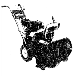
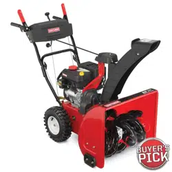
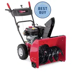
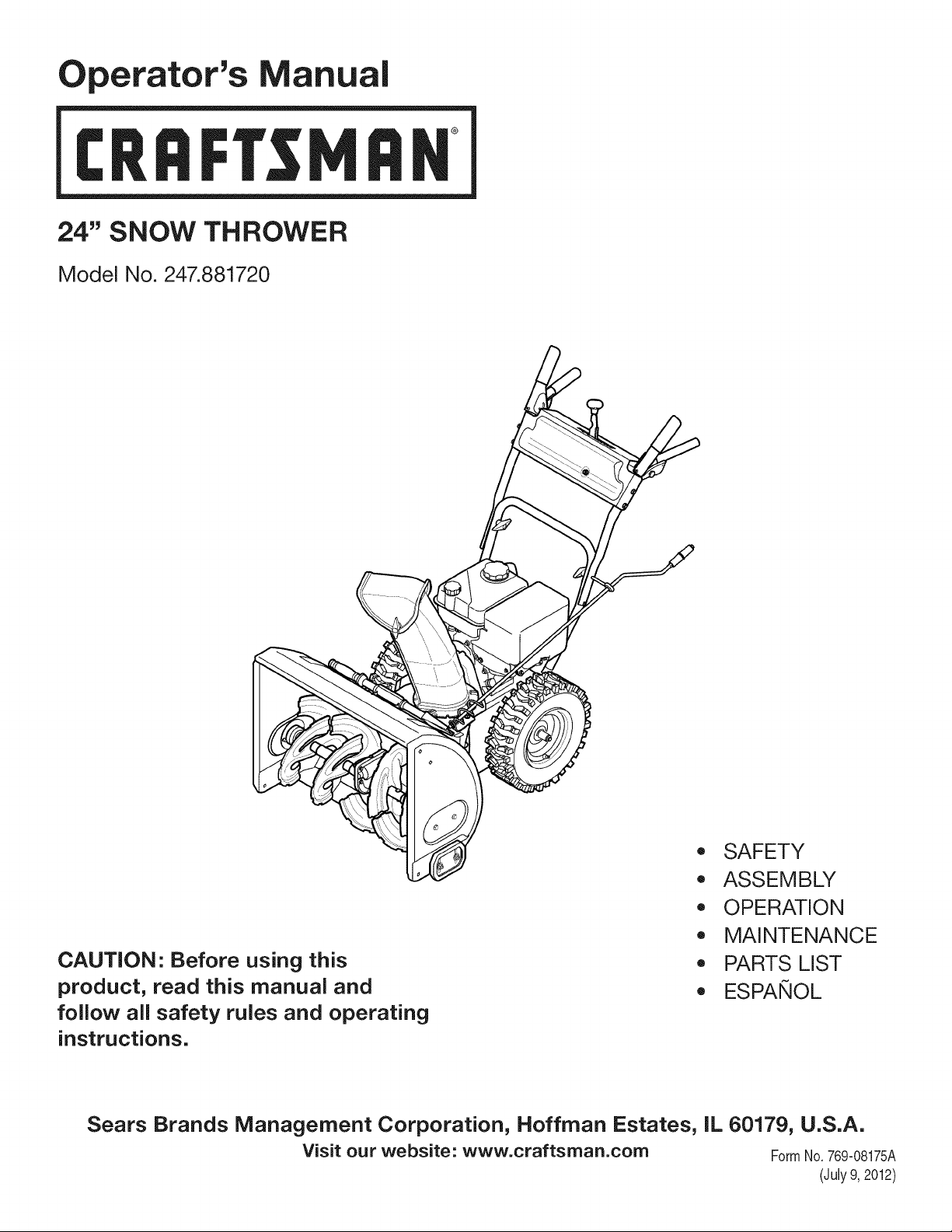
24" SNOW THROWER
Model No. 247.881720
CAUTION" Before using this
product, read this manual and
follow all safety rules and operating
instructions.
,, SAFETY
o ASSEMBLY
OPERATION
MAINTENANCE
PARTS LIST
o ESPANOL
Sears Brands Management Corporation, Hoffman Estates, IL 60179, U.S.A.
Visit our website: www.craftsman.com FormNo.769-08175A
(July9, 2012)
WarrantyStatement.................... Page2
SafeOperationPractices.............. Pages3-6
Assembly......................... Pages8-11
Operation........................ Pages12-15
Service&Maintenance.............. Pages16-23
Off-SeasonStorage................... Page24
Troubleshooting...................... Page25
PartsList......................... Pages26-43
RepairProtectionAgreement............ Page47
Espadol............................. Page48
CRAFTSMANTWOYEARFULL WARRANTY
FORTWOYEARSfromthedateofpurchase,thisproductiswarrantedagainstanydefectsinmaterialorworkmanship.Defectiveproductwill
receivefreerepairorfreereplacementifrepairisunavailable.
Forwarrantycoverage details to obtain repairor replacement,visit the website: www.craftsman.com
This warranty covers ONLYdefects in material andworkmanship. Warranty coverage does NOTinclude:
• Expendableitemsthatcan wearoutfromnormalusewithinthewarrantyperiod,includingbut not limitedto augers,auger paddles,drift
cutters,skidshoes,shaveplate, shearpins,sparkplug,air cleaner,belts,andoil filter.
• Standardmaintenanceservicing,oilchanges,or tune-ups.
• Tire replacementor repaircausedby puncturesfrom outsideobjects,such as nails,thorns,stumps,or glass.
• Tireor wheelreplacementor repairresultingfromnormalwear,accident,or improperoperationor maintenance.
Repairsnecessarybecauseof operatorabuse, includingbutnot limitedto damagecausedby over-speedingthe engine,or fromimpacting
objectsthat bendthe frame,auger shaft,etc.
• Repairsnecessarybecauseof operatornegligence,includingbut not limitedto,electricalandmechanicaldamagecausedby improper
storage,failureto usethe propergradeandamountof engineoil, or failureto maintainthe equipmentaccordingto the instructionscontained
inthe operator'smanual.
• Engine(fuelsystem)cleaningor repairscausedbyfuel determinedto be contaminatedor oxidized(stale).In general,fuel shouldbeused
within30 daysof its purchasedate.
Normaldeteriorationandwearof the exteriorfinishes,or productlabel replacement.
Thiswarrantyis void if this productis ever usedwhileprovidingcommercialservicesor if rentedto anotherperson.
Thiswarrantygivesyou specificlegal rights,andyou mayalso haveotherrightswhichvaryfromstateto state.
Sears Brands Management Corporation, Hoffman Estates, IL 60179
EngineOilType: 5W-30
EngineOilCapacity: 20ounces
FuelCapacity: 2 Quarts
SparkPlug: F6RTC(951-10292)
SparkPlugGap: .020"to .030"
Model Number.................................................................
Serial Number .................................................................
Dateof Purchase .............................................................
Recordthe modelnumber,serialnumber
anddateof purchaseabove
© Sears Brands,LLC
2
Thissymbolpointsout importantsafetyinstructionswhich,if not
followed,couldendangerthepersonalsafetyand/orpropertyof
yourselfand others. Readandfollowall instructionsin thismanual
beforeattemptingto operatethismachine.Failureto complywith
theseinstructionsmay resultin personalinjury.Whenyou seethis
symbol,HEEDITSWARNING!
CALIFORNIA PROPOSITION 65
EngineExhaust,someof itsconstituents,andcertainvehicle
componentscontainoremitchemicalsknownto Stateof California
to causecancerandbirthdefectsorotherreproductiveharm,
Thismachinewasbuiltto beoperatedaccordingto the safeopera-
tion practicesinthis manual.As with anytype of powerequipment,
carelessnessor error on the partof the operatorcan resultin serious
injury.Thismachineis capableof amputatingfingers,hands,toes
andfeetandthrowingdebris.Failureto observethe followingsafety
instructionscouldresultin seriousinjuryor death.
Your Responsibility--Restrict the use of thispowermachineto
personswho read,understandandfollowthewarningsand instruc-
tionsin this manualandon the machine,
SAVE THESE INSTRUCTIONS!
TRAiNiNG
• Read,understand,and followall instructionson the machineand
in themanual(s)beforeattemptingto assembleandoperate.
Failureto do socan resultinseriousinjuryto the operatorand/
orbystanders.Keepthis manualin a safeplaceforfutureand
regularreferenceandfor orderingreplacementparts.
• Befamiliarwithall controlsandtheir properoperation.Knowhow
to stopthe machineanddisengagethemquickly.
• Neverallowchildrenunder 14 yearsof age to operatethis
machine.Children14andover shouldreadandunderstandthe
instructionsand safe operationpracticesin this manualandon
the machineandbe trainedandsupervisedby anadult.
Neverallowadultsto operatethis machinewithoutproper
instruction.
• Thrownobjectscan causeseriouspersonalinjury. Planyour
snow-throwingpatternto avoiddischargeof materialtoward
roads,bystandersandthe like.
Keepbystanders,pets and childrenat least75feetfromthe
machinewhile it is in operation.Stopmachineif anyoneenters
the area.
• Exercisecautionto avoidslippingor falling,especiallywhen
operatingin reverse.
PREPARATION
Thoroughlyinspectthearea wherethe equipmentisto be used.
Removeall doormats,newspapers,sleds,boards,wiresandother
foreignobjects,whichcouldbe trippedoveror thrownby the auger/
impeller.
• Alwayswear safetyglassesor eyeshieldsduringoperationand
while performingan adjustmentor repairto protectyoureyes.
Thrownobjectswhichricochetcancause seriousinjuryto the
eyes.
Donot operatewithoutwearingadequatewinteroutergarments.
Donot wearjewelry,long scarvesor otherlooseclothing,which
could becomeentangledin movingparts.Wearfootwearwhich
will improvefootingonslipperysurfaces.
Usea groundedthree-wireextensioncordand receptaclefor all
machineswith electricstartengines.
Disengageall controlleversbeforestartingthe engine.
Adjustcollectorhousingheightto cleargravelorcrushedrock
surfaces.
• Neverattemptto make anyadjustmentswhileengineis running,
exceptwherespecificallyrecommendedinthe operator'smanual.
Letengineandmachineadjustto outdoortemperaturebefore
startingto clearsnow.
3

Safe Handling of Gasoline
Toavoidpersonalinjuryor propertydamageuseextremecare in
handlinggasoline.Gasolineis extremelyflammableandthe vaporsare
explosive.Seriouspersonalinjurycan occurwhengasolineis spilled
onyourselfor yourclotheswhichcan ignite. Washyour skin and
changeclothesimmediately.
• Useonlyan approvedgasolinecontainer.
• Extinguishall cigarettes,cigars,pipesand other sourcesof
ignition.
• Neverfuel machineindoors.
• Neverremovegas capor add fuel whilethe engineis hot or
running.
• Allowengineto coolat leasttwo minutesbeforerefueling.
• Neveroverfill fueltank. Fill tankto nomorethan1/2inchbelow
bottomof filler neck to providespaceforfuel expansion.
• Replacegasolinecapandtightensecurely.
• Ifgasolineis spilled,wipe it off theengineand equipment.Move
machineto anotherarea.Wait5 minutesbeforestartingthe
engine.
• Neverstorethe machineorfuel containerinsidewherethereis an
openflame,sparkor pilotlight(e.g. furnace,waterheater,space
heater,clothesdryeretc.).
• Allowmachineto cool at least5 minutesbeforestoring.
• Neverfill containersinsidea vehicleor ona truckor trailerbed
witha plasticliner.Alwaysplacecontainersonthe groundaway
fromyour vehiclebeforefilling.
• If possible,removegas-poweredequipmentfromthe truckor
trailerandrefuelit onthe ground.Ifthis is not possible,then refuel
suchequipmenton a trailerwitha portablecontainer,ratherthan
froma gasolinedispensernozzle.
• Keepthe nozzlein contactwiththe rimof the fuel tankor
containeropeningat alltimes untilfuelingis complete.Do not use
a nozzlelock-opendevice.
OPERATION
• Do not puthandsorfeetnear rotatingparts,in the auger/impeller
housingor chuteassembly.Contactwith the rotatingpartscan
amputatehandsandfeet.
• Theauger/impellercontrolleveris a safetydevice.Neverbypass
itsoperation.Doingso makesthe machineunsafeandmaycause
personalinjury.
• Thecontrolleversmustoperateeasilyin bothdirectionsand
automaticallyreturnto the disengagedpositionwhenreleased.
• Neveroperatewith a missingor damagedchuteassembly.Keep
all safetydevicesin placeand working.
• Neverrunanengineindoorsor ina poorlyventilatedarea. Engine
exhaustcontainscarbonmonoxide,an odorlessanddeadlygas.
• Do notoperatemachinewhileunderthe influenceof alcoholor
drugs.
• Mufflerand engine becomehotand can causea burn.Do not
touch.Keepchildrenaway.
• Exerciseextremecautionwhenoperatingon or crossinggravel
surfaces.Stay alertfor hidden hazardsor traffic.
Exercisecautionwhenchangingdirectionandwhileoperatingon
slopes.Do notoperateon steepslopes.
Planyoursnow-throwingpatternto avoiddischargetowards
windows,walls,carsetc. Thus,avoidingpossibleproperty
damageor personalinjurycausedby a ricochet.
Neverdirectdischargeat children,bystandersand petsor allow
anyoneinfrontof the machine.
Donot overloadmachinecapacityby attemptingto clearsnowat
too fastof a rate.
Neveroperatethis machinewithoutgoodvisibilityorlight.Always
be sureof yourfootingand keepa firmholdon the handles.Walk,
neverrun.
Disengagepowerto theauger/impellerwhentransportingor not
in use.
Neveroperatemachineat hightransportspeedson slippery
surfaces.Lookdownand behindand usecare whenbackingup.
Ifthe machineshouldstart to vibrateabnormally,stopthe engine,
disconnectthe sparkplugwire andgroundit againstthe engine.
Inspectthoroughlyfor damage.Repairanydamagebefore
startingandoperating.
Disengageall controlleversand stop enginebeforeyouleave
the operatingposition(behindthe handles).Waituntilthe auger/
impellercomesto a completestop beforeuncloggingthechute
assembly,makingany adjustments,or inspections.
Neverput yourhandinthe dischargeor collectoropenings.Do
not unclogchuteassemblywhileengineis running.Shutoff
engineand remainbehindhandlesuntilall movingpartshave
stoppedbeforeunclogging.
Useonly attachmentsandaccessoriesapprovedby the manufac-
turer (e.g.wheelweights,tire chains,cabsetc.). Forinformation
concerningtheseitems,call 1-800-469-4663.
Whenstartingengine,pull cord slowlyuntilresistanceis felt, then
pull rapidly.Rapidretractionof startercord(kickback)will pull
handandarmtowardenginefasterthan youcan let go. Broken
bones,fractures,bruisesor sprainscould result.
Ifsituationsoccurwhichare notcoveredin this manual,use care
andgoodjudgment.
Toorderpartsor scheduleservicefor this product,call 1-800-
469-4663.
CLEARING A CLOGGED DISCHARGE CHUTE
Handcontactwith the rotatingimpellerinsidethe dischargechute
is the mostcommoncauseof injuryassociatedwith snowthrowers.
Neveruse yourhandto cleanout thedischargechute.
Toclear thechute:
1. SHUTTHEENGINEOFF!
2. Wait 10secondsto be surethe impellerbladeshavestopped
rotating.
3. Alwaysusea clean-outtool,not yourhands.
4
MAINTENANCE & STORAGE
• Nevertamperwithsafetydevices.Checktheirproperoperation
regularly.Referto the maintenanceand adjustmentsectionsof
thismanual.
• Beforecleaning,repairing,or inspectingmachinedisengageall
controlleversandstopthe engine.Waituntilthe auger/impeller
cometo a completestop.Disconnectthe sparkplug wireand
groundagainsttheengineto preventunintendedstarting.
Checkboltsand screwsfor propertightnessat frequentintervals
to keepthe machineinsafeworkingcondition.Also, visually
inspectmachinefor anydamage.
Do notchangetheenginegovernorsettingor over-speedthe
engine.Thegovernorcontrolsthe maximumsafeoperatingspeed
of the engine.
Snowthrowershaveplatesand skid shoesaresubjectto wear
anddamage.Foryoursafetyprotection,frequentlycheckall
componentsand replacewithoriginalequipmentmanufacturer's
(OEM)partsonlyas listedinthe Partspagesof this operator's
manual.Useof partswhichdonot meetthe originalequipment
specificationsmayleadto improperperformanceandcompro-
misesafety!
Checkcontrolleversperiodicallyto verifytheyengageanddisen-
gageproperlyand adjust,if necessary.Referto the adjustment
sectioninthisoperator'smanualfor instructions.
Maintainor replacesafetyand instructionlabels,as necessary.
Observeproperdisposallawsand regulationsfor gas,oil,etc. to
protectthe environment.
Priorto storing,run machinea few minutestoclear snowfrom
machineand preventfreezeup of auger/impeller.
Neverstorethe machineorfuel containerinsidewherethereisan
openflame,spark or pilot lightsuch as a waterheater,furnace,
clothesdryer etc.
Alwaysreferto the operator'smanualfor properinstructionson
off-seasonstorage.
Checkfuelline,tank, cap,andfittingsfrequentlyfor cracksor
leaks.Replaceif necessary.
Do notcrankenginewithsparkplugremoved.
Accordingto the ConsumerProductsSafetyCommission(CPSC)
andthe U.S.EnvironmentalProtectionAgency(EPA),this product
hasan AverageUsefulLifeof seven(7) years,or 60 hoursof
operation.At the endof theAverageUsefulLifehavethe machine
inspectedannuallybyan authorizedservicedealerto ensurethat
allmechanicaland safetysystemsare workingproperlyand not
wornexcessively.Failureto do so can resultin accidents,injuries
ordeath.
DO NOT MODIFY ENGINE
Toavoidseriousinjuryor death,do not modifyengine in any way.
Tamperingwiththe governorsettingcanlead to a runawayengineand
causeit to operateat unsafespeeds.Nevertamperwithfactorysetting
of enginegovernor.
NOTICE REGARDING EMiSSiONS
Engineswhich are certifiedtocomplywith Californiaand federal
EPAemissionregulationsfor SORE(SmallOff RoadEquipment)are
certifiedto operateon regularunleadedgasoline,and mayinclude
the followingemissioncontrol systems:EngineModification(EM),
OxidizingCatalyst(OC), SecondaryAir Injection(SAI)and ThreeWay
Catalyst(TWO)if so equipped.
SPARK ARRESTOR
Thismachineisequippedwithaninternalcombustionengineand
shouldnotbe usedon or nearany unimprovedforest-covered,
brush-coveredor grass-coveredland unlessthe engine'sexhaust
systemisequippedwith a sparkarrestormeetingapplicablelocalor
statelaws(if any)
Ifa sparkarrestoris used, it shouldbe maintainedin effectiveworking
orderby theoperator.Inthe Stateof Californiathe aboveis required
bylaw (Section4442of the CaliforniaPublicResourcesCode).Other
statesmayhavesimilarlaws. Federallawsapplyon federallands.
A spark arrestorfor the muffleris availablethroughyournearestSears
PartsandRepairServiceCenter.
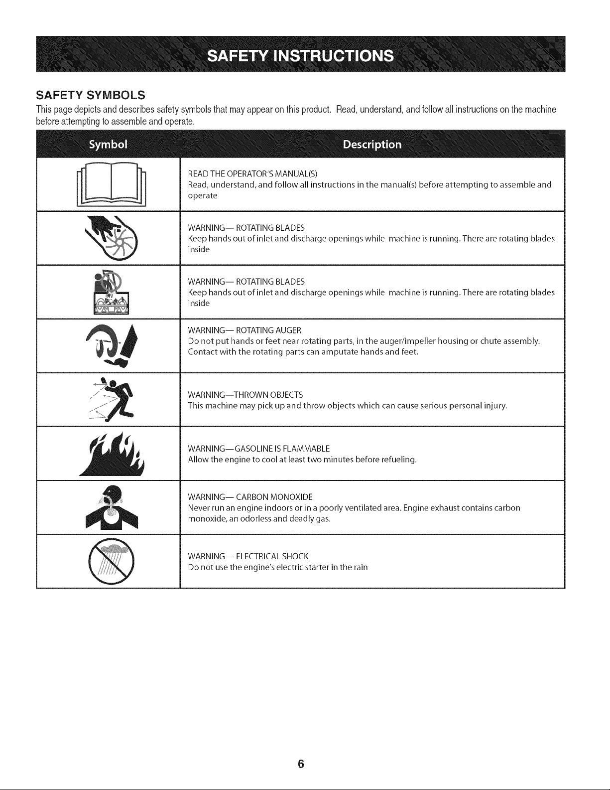
SAFETY SYMBOLS
Thispagedepictsanddescribessafetysymbolsthatmayappearonthisproduct. Read,understand,and followall instructionson the machine
beforeattemptingto assembleandoperate.
. +
i
i
"JIp
READ THE OPERATOR'S MANUAL(S)
Read, understand, and follow all instructions in the manual(s) before attempting to assemble and
operate
WARNING-- ROTATING BLADES
Keep hands out of inlet and discharge openings while machine is running. There are rotating blades
inside
WARNING-- ROTATING BLADES
Keep hands out of inlet and discharge openings while machine is running. There are rotating blades
inside
WARNING-- ROTATING AUGER
Do not put hands or feet near rotating parts, in the auger/impeller housing or chute assembly.
Contact with the rotating parts can amputate hands and feet.
WARNING--THROWN OBJECTS
This machine may pick up and throw objects which can cause serious personal injury.
WARNING--GASOLINE IS FLAMMABLE
Allow the engine to cool at least two minutes before refueling.
WARNING-- CARBON MONOXIDE
Never run an engine indoors or in a poorly ventilated area. Engine exhaust contains carbon
monoxide, an odorless and deadly gas+
WARNING-- ELECTRICAL SHOCK
Do not use the engine's electric starter in the rain
6

Thispageleftintentionallyblank.
7
NOTE:Referencesto rightorleft sideof the snowthrowerare
determinedfrombehindthe unit inthe operatingposition(standing
directlybehindthe snowthrower,facingthe handlepanel).
REMOVING FROM CARTON
1. Cut the cornersof thecarton and lay the sidesflat on the ground.
Removeand discard all packinginserts.
2. Movethe snowthrowerout of thecarton.
3. Makecertainthe carton has beencompletelyemptiedbefore
discardingit.
ASSEMBLY
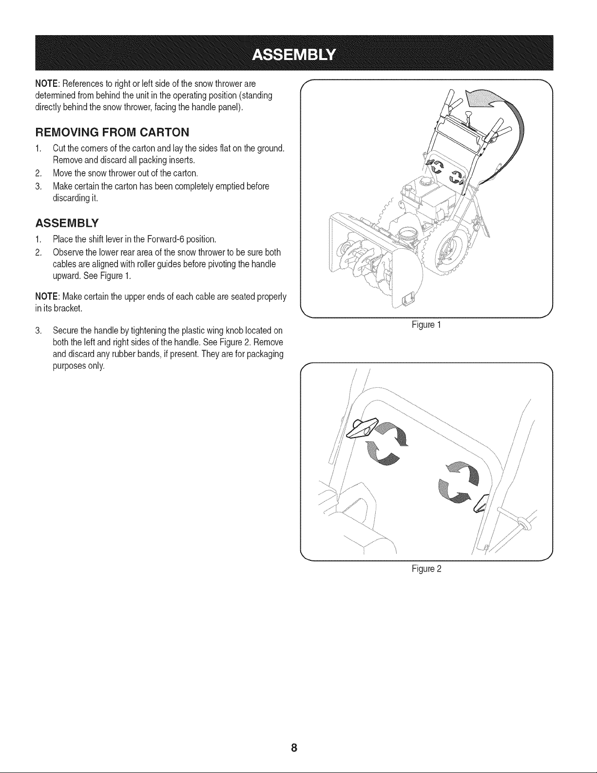
1. Placethe shiftleverin the Forward-6position.
2. Observethe lowerreararea of the snowthrowerto be sure both
cablesarealignedwith rollerguidesbeforepivotingthe handle
upward.See Figure1.
NOTE:Makecertainthe upperends of eachcableare seatedproperly
in its bracket.
.
Securethe handleby tighteningthe plasticwingknob locatedon
boththe leftand rightsides of the handle.SeeFigure2. Remove
anddiscardany rubberbands,if present.Theyarefor packaging
purposesonly.
\
Figure1
f
Figure2
8
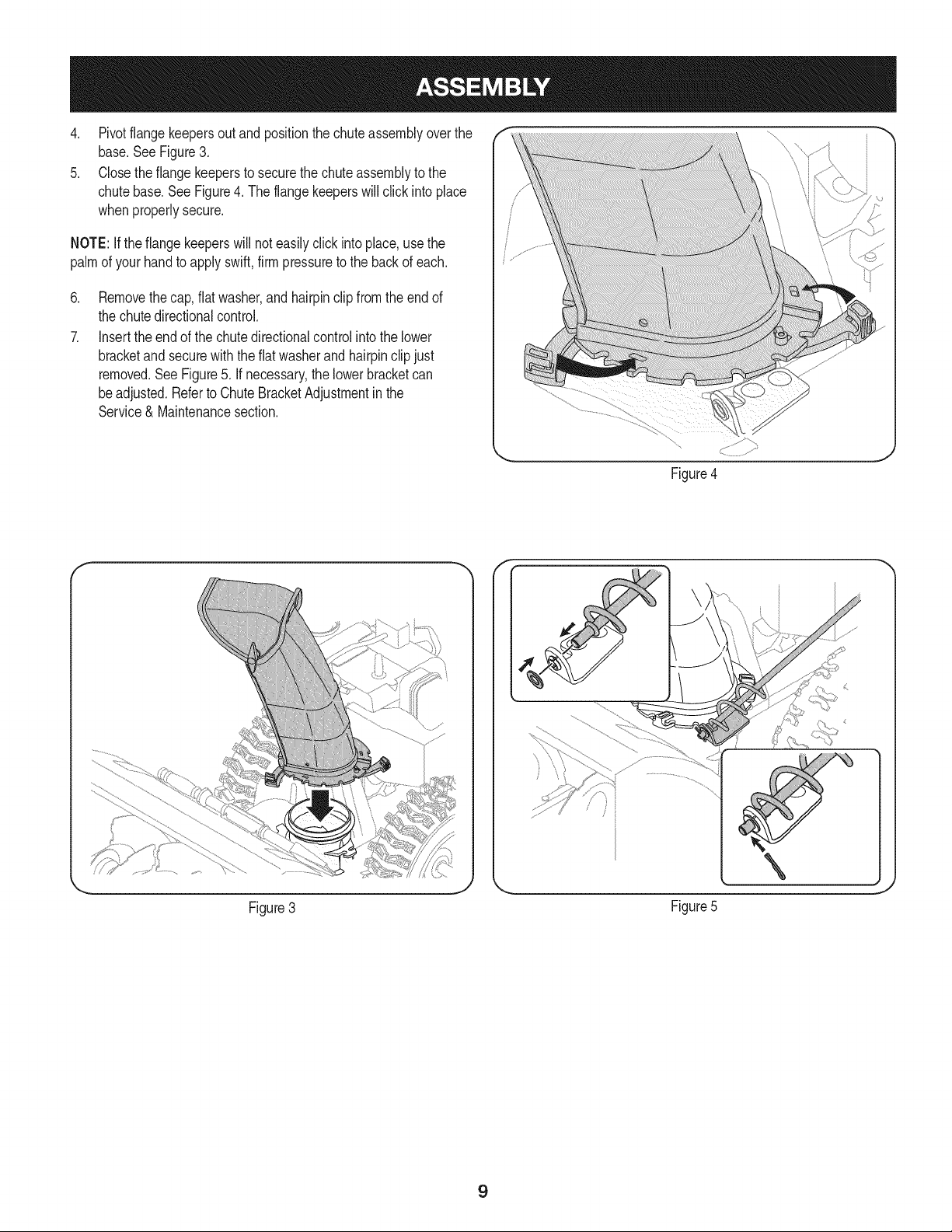
4. Pivotflangekeepersoutand positionthe chuteassemblyoverthe
base.SeeFigure3.
5. Closethe flangekeepersto securethe chute assemblyto the
chutebase.SeeFigure4. The flangekeeperswill clickinto place
whenproperlysecure.
NOTE:Ifthe flangekeeperswill noteasilyclickinto place,usethe
palmof yourhandto applyswift,firmpressureto the backof each.
.
7.
Removethecap, flat washer,andhairpinclip fromthe endof
the chutedirectionalcontrol.
Insertthe endof the chutedirectionalcontrolinto the lower
bracketand securewith the flat washerandhairpinclipjust
removed.See Figure5. If necessary,the lowerbracketcan
beadjusted.Referto ChuteBracketAdjustmentin the
Service& Maintenancesection.
Figure4
f F
Figure3
\
J
Figure5
9
SET-UP
Chute Clean-Out Tool
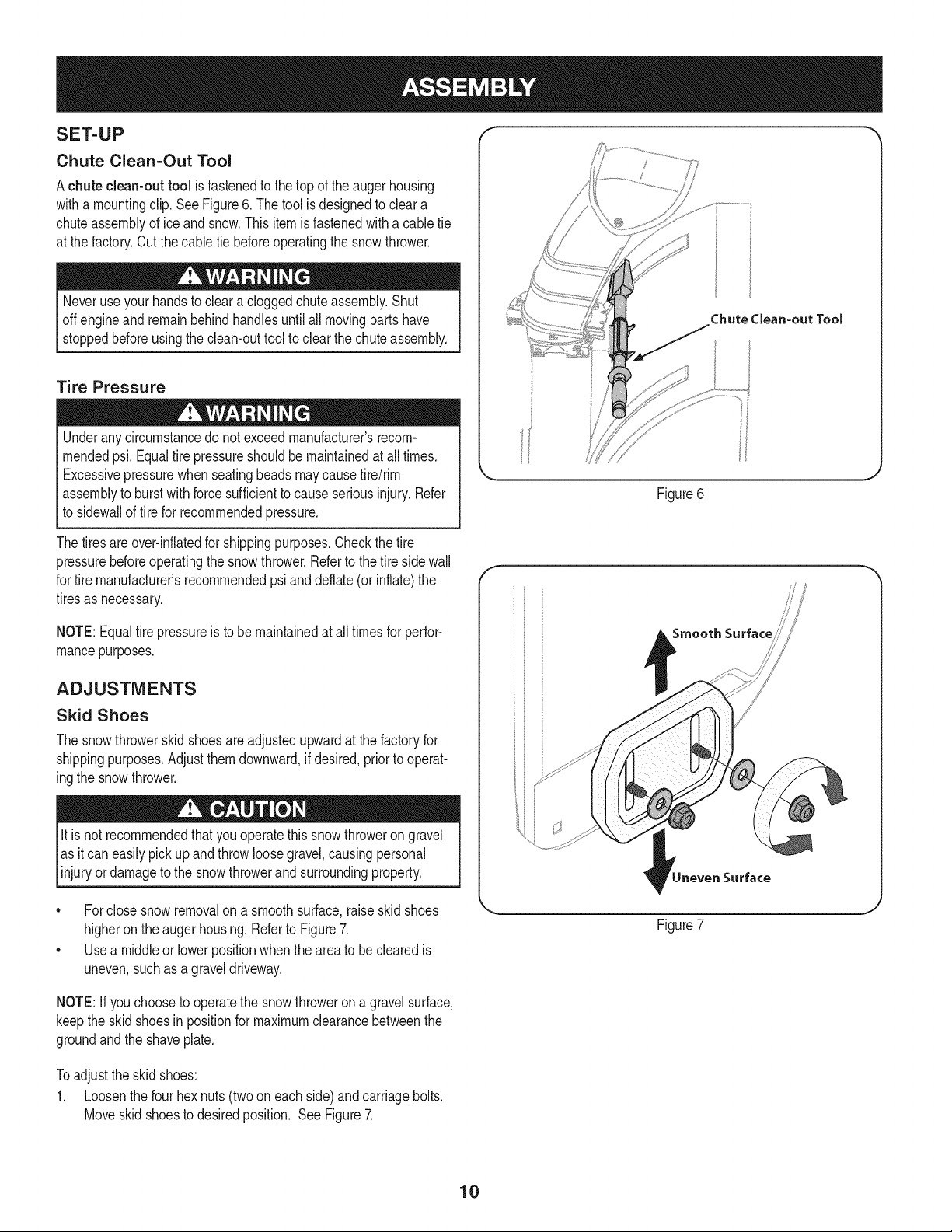
Achute clean-out tool is fastenedto the top of the augerhousing
witha mountingclip. See Figure6. The tool is designedto cleara
chuteassemblyof ice andsnow.This item is fastenedwitha cabletie
at the factory.Cut thecable tie beforeoperatingthe snowthrower.
Neveruseyour handsto cleara cloggedchuteassembly.Shut
offengineand remainbehindhandlesuntilall movingpartshave
stoppedbeforeusingthe clean-outtool to clear thechuteassembly.
Tire Pressure
Underanycircumstancedo notexceed manufacturer'srecom-
mendedpsi. Equaltire pressureshouldbe maintainedat all times.
Excessivepressurewhenseatingbeadsmaycausetire/rim
assemblyto burstwithforcesufficientto causeseriousinjury. Refer
to sidewallof tirefor recommendedpressure.
Thetiresareover-inflatedfor shippingpurposes.Checkthetire
pressurebeforeoperatingthe snow thrower.Referto the tire sidewall
for tiremanufacturer'srecommendedpsianddeflate(or inflate)the
tiresas necessary.
NOTE:Equaltire pressureis to be maintainedat all timesfor perfor-
mancepurposes.
ADJUSTMENTS
Skid Shoes
The snowthrowerskidshoesareadjustedupwardat thefactoryfor
shippingpurposes.Adjustthemdownward,if desired,priorto operat-
ingthe snowthrower.
It is not recommendedthatyouoperatethis snowthrowerongravel
as it can easilypickup and throwloosegravel,causingpersonal
njuryordamageto the snowthrowerand surroundng property.
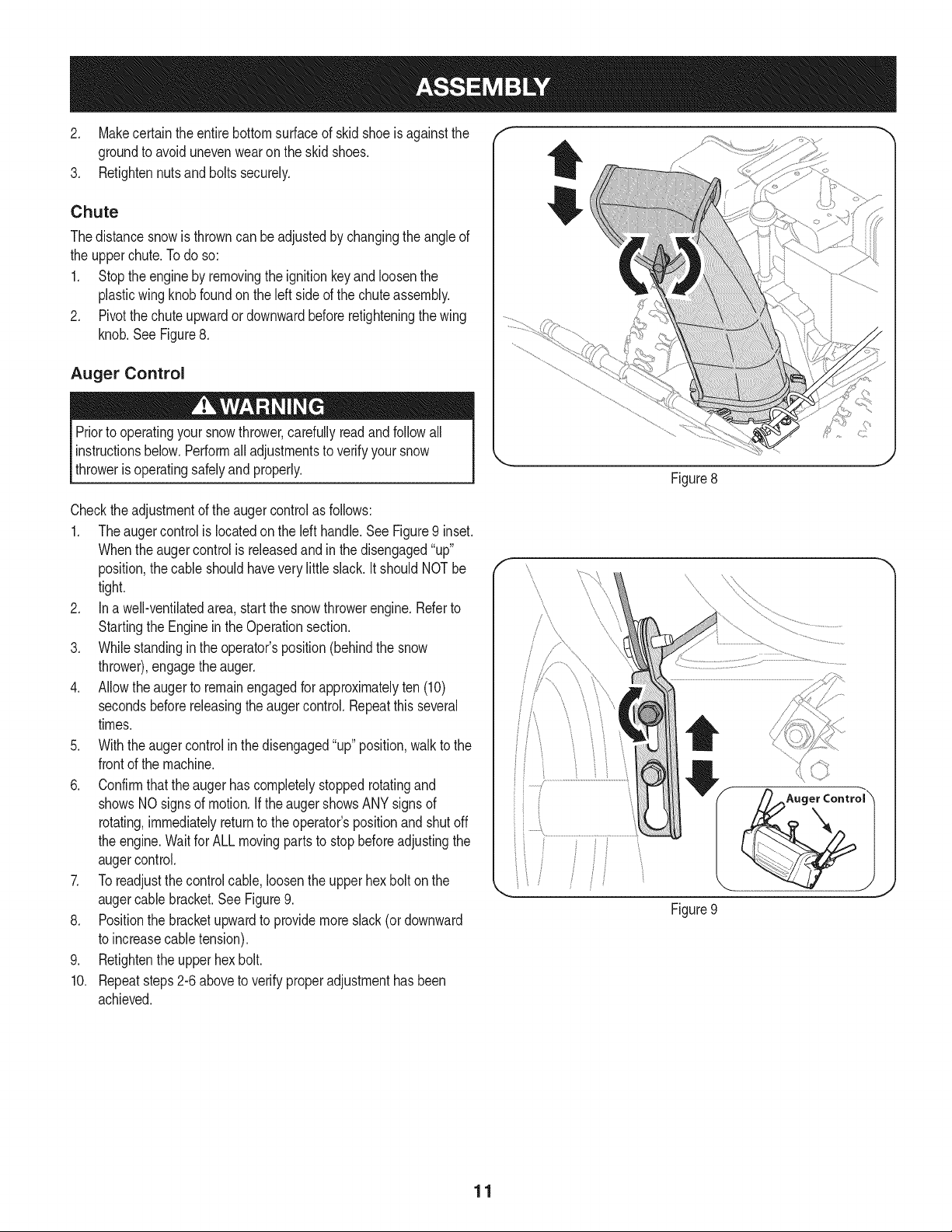
• Forclosesnowremovalona smoothsurface,raiseskid shoes
higheronthe augerhousing.Referto Figure7.
• Usea middleor lowerpositionwhenthearea to be clearedis
uneven,suchas a graveldriveway.
Chute Clean=out Tool
Figure6
f
Smooth Surface
Surface
Figure7
NOTE:If youchooseto operatethe snowthrowerona gravelsurface,
keepthe skidshoesin positionfor maximumclearancebetweenthe
groundandthe shaveplate.
Toadjustthe skidshoes:
1. Loosenthe four hexnuts(twooneach side)andcarriagebolts.
Moveskidshoesto desiredposition. SeeFigure7.
10
2, Makecertain theentirebottomsurfaceof skidshoeis againstthe f
groundto avoidunevenwearon the skid shoes, ....
3. Retightennutsandboltssecurely.
Chute
Thedistancesnowis throwncan beadjustedby changingthe angle of
the upperchute.Todo so:
1. Stopthe engineby removingthe ignitionkeyandloosenthe
plasticwingknobfoundonthe left sideof the chuteassembly.
2. Pivotthe chute upwardordownwardbeforeretighteningthewing
knob.See Figure8.
Auger Control
Priorto operatingyoursnowthrower,carefullyreadand followall
instructionsbelow.Performall adjustmentsto verifyyour snow
throweris operatingsafelyand properly.
Figure8
Checktheadjustmentof the augercontrolas follows:
1. Theaugercontrolis locatedonthe left handle.SeeFigure9 inset.
Whentheaugercontrolis releasedand in the disengaged"up"
position,the cableshouldhavevery little slack. It shouldNOTbe
tight.
2. In a well-ventibtedarea,start the snowthrowerengine.Referto
Startingthe Engineinthe Operationsection.
3. Whilestandingin the operator'sposition(behindthe snow
thrower),engagethe auger.
4. Allowtheauger to remainengagedfor approximatelyten (10)
secondsbeforereleasingthe augercontrol.Repeatthisseveral
times.
5. With theauger controlin thedisengaged"up" position,walkto the
frontof the machine.
6. Confirmthatthe augerhas completelystoppedrotatingand
showsNOsignsof motion.If the augershowsANYsignsof
rotating,immediatelyreturnto the operator'spositionand shutoff
the engine.Waitfor ALL movingparts to stopbeforeadjustingthe
augercontrol.
7. Toreadjustthecontrolcable, loosentheupper hexbolt on the
augercablebracket.SeeFigure9.
8. Positionthe bracketupwardto providemoreslack(or downward
to increasecabletension).
9. Retightenthe upperhex bolt.
10. Repeatsteps2-6 aboveto verifyproperadjustmenthasbeen
achieved.
\
ii
Figure9
11
f
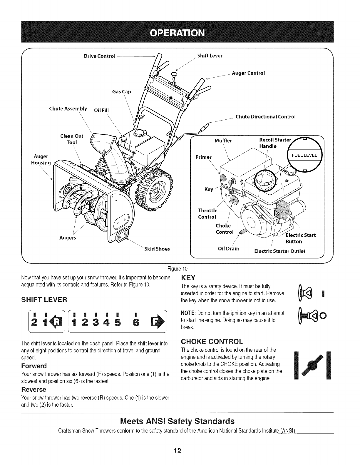
Drive Control
Shift Lever
J
Auger Control
ChuteAssembly
\,
Auger
Housing
\
Augers
Gas Cap
\
OilFill
\\\\
\\
\
Skid Shoes
_jjjj Chute Directional Control
Mumer RecoilStarter
ndle
\
\
Key
Figure10
Nowthat youhaveset up yoursnowthrower,it'simportantto become KEY
acquaintedwith its controlsandfeatures,Referto Figure10, The keyis a safetydevice.It mustbe fully
insertedinorderfor the engineto start, Remove
SHIFT LEVER the keywhenthe snowthroweris not in use,
'
1 2345 6
NOTE: Donot turnthe ignitionkey inan attempt
to startthe engine,Doingso may causeitto
break.
The shiftleveris locatedonthe dash panel.Placethe shift leverinto
anyof eight positionsto controlthe directionof travel and ground
speed.
Forward
Yoursnowthrowerhas sixforward(F) speeds.Positionone(1)is the
slowestandpositionsix(6) is the fastest.
Reverse
Yoursnowthrowerhastwo reverse(R) speeds.One (1) is the slower
andtwo(2) is the faster.
CHOKE CONTROL
The chokecontrolis foundon the rearof the
engineand is activatedby turningthe rotary
chokeknobto the CHOKEposition.Activating
the chokecontrolclosesthe chokeplateon the
carburetorandaids instartingthe engine.
J
Meets ANSi Safety Standards
CraftsmanSnowThrowersconformto the safetystandardof the AmericanNationalStandardsInstitute(ANSI).
12
THROTTLE CONTROL
aiW'
Thethrottlecontrolis locatedon the rearof the engine.It regulatesthe
speedof theengineandwill shutoff the enginewhenmovedintothe
STOPposition.
r 1
Depressingthe primerforcesfuel directlyinto __<<<
the engine'scarburet°rt° aid inc°'dweather [k, _"_'-_ 3X Jstarting.
RECOIL STARTER HANDLE
Thishandleis usedto manuallystartthe engine.
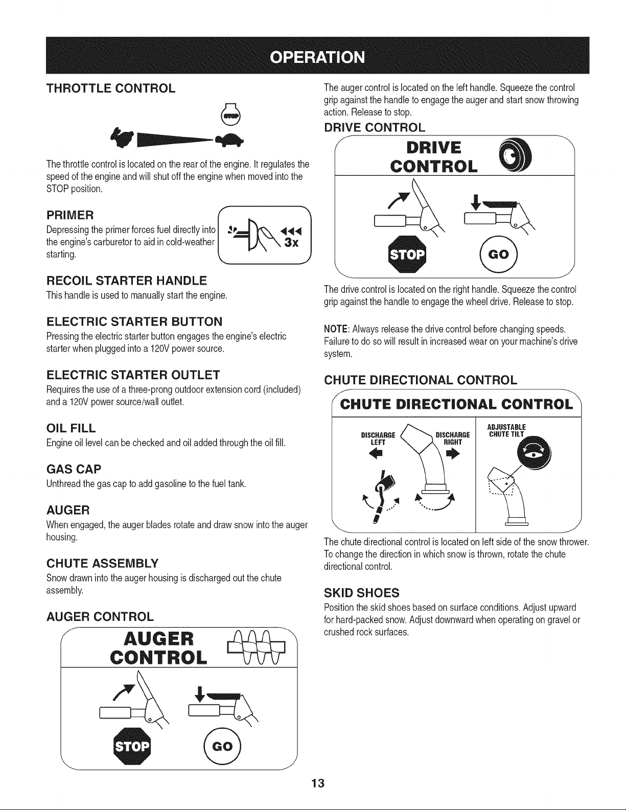
The augercontrolis locatedon the lefthandle.Squeezethe control
gripagainstthe handleto engagethe augerand startsnowthrowing
action.Releaseto stop.
DRIVE CONTROL
J DRIVE
CONTROL
The drivecontrolis locatedon the righthandle.Squeezethe control
gripagainstthe handleto engagethe wheeldrive.Releaseto stop.
ELECTRIC STARTER BUTTON
Pressingthe electricstarterbuttonengagesthe engine'selectric
starterwhenpluggedintoa 120Vpowersource.
NOTE:Alwaysreleasethedrivecontrolbeforechangingspeeds.
Failureto do so will result in increasedwearon yourmachine'sdrive
system.
ELECTRIC STARTER OUTLET
Requiresthe useof athree-prongoutdoorextensioncord(included)
anda 120Vpowersource/walloutlet.
CHUTE DIRECTIONAL CONTROL
:c.uT,=D,.EcTIo.A.co.T.o
OIL FILL
Engineoil levelcan becheckedand oil addedthroughtheoil fill.
GAS CAP
Unthreadthe gascap to addgasolineto the fuel tank.
AUGER
Whenengaged,the auger bladesrotateand drawsnowintothe auger
housing.
CHUTE ASSEMBLY
Snowdrawninto theauger housingis dischargedout the chute
assembly.
AUGER CONTROL
ADJUSTABLE
DISCHARGE DISCHARGE CHUTETiLT
LEFT
The chute directional control is located on left side d the snow thrower.
Tochange the direction inwhich snow is thrown, rotate the chute
directional control.
SKID SHOES
Positionthe skidshoesbasedonsurfaceconditions.Adjustupward
for hard-packedsnow.Adjustdownwardwhenoperatingon gravelor
crushedrocksurfaces.
13
CLEAN-OUT TOOL
Neveruse yourhandsto cleara cloggedchuteassembly.Shut
off engineand remainbehindhandlesuntilall movingpartshave
stoppedbeforeusingthe clean-outtoolto clear thechute assembly.
Thechuteclean-outtool is convenientlyfastenedto the rear of the
augerhousingwith a mountingclip. Shouldsnowandice become
lodgedin thechute assemblyduringoperation,proceedas followsto
safelycleanthechuteassemblyandchuteopening:
1. Releaseboththe AugerControland the DriveControl.
2. Stopthe engineby removingthe ignitionkey.
3. Removethe clean-outtoolfromthe clip whichsecuresit to the
rearof the augerhousing.
4. Use the shovel-shapedendof theclean-outtool to dislodgeand
scoopany snowand icewhich hasformedin andnearthechute
assembly.
5. Refastenthe clean-outtool to the mountingclip on the rear of the
augerhousing,reinsertthe ignitionkeyandstart thesnow
thrower'sengine.
6. Whilestandingin the operator'sposition(behindthesnow
thrower),engagethe auger controlfora fewsecondsto clear any
remainingsnowand ice from thechute assembly.
BEFORE STARTING ENGINE
Read,understand,and followall instructionsand warningson the
machineand in this manualbeforeoperating.
Oil
Theunit wasshippedwith oil in the engine.Checkoil levelbefore
eachoperationto ensureadequateoil inthe engine.Forfurther
instructions,refertothe stepson page16.
NOTE:Besureto checkthe engineon a levelsurfacewith the engine
stopped.
1. Removethe oil fillercap/dipstickand wipethe dipstickclean.
2. insertthe cap/dipstickintothe oil filler neck,butdo NOTscrewit
in.
3. Removethe oil fillercap/dipstick,ifthe levelislow,slowlyadd
oil (5%30, with a minimumclassificationof SF/SG)untiloil level
registersbetweenhigh (H) and low(L).
NOTE:Do notoverfill.Overfillingwithoil mayresult inenginesmoking,
hardstartingor sparkplugfouling.
4. Replaceand tighten cap/dipstickfirmlybeforestartingengine.
Gasoline
Useautomotivegasoline(unleadedor low leadedto minimizecombus-
tionchamberdeposits)with a minimumof 87 octane.Gasolinewith
upto 10%ethanolor 15%MTBE(MethylTertiaryButylEther)canbe
used.Neveruseanoil/gasolinemixtureor dirtygasoline.Avoidgetting
dirt,dust,or waterin thefuel tank. DO NOTuse E85gasoline.
• Refuelin a well-ventilatedareawiththe enginestopped.Do not
smokeorallowflamesor sparksin the areawherethe engineis
refueledor wheregasolineisstored.
• Donot overfillthe fueltank.After refueling,makesurethe tank
cap is closedproperlyand securely.
• Be carefulnotto spillfuel whenrefueling.Spilledfuel or fuel vapor
mayignite,ifany fuelis spilled,makesurethe area isdry before
startingthe engine.
• Avoidrepeatedor prolongedcontact with skinor breathingof
)or.
Useextremecarewhen handlinggasoline.Gasolineis extremely
flammableand thevaporsare explosive.Neverfuelthe machine
indoorsorwhilethe engineishotor running.Extinguishcigarettes,
cigars,pipesandothersourcesof ignition.
1. Cleanaroundfuel fill beforeremovingcap to fuel.
2. A fuel levelindicatorislocatedin the fueltank. See Figure10
inset.Be carefulnotto overfill.Filltank untilfuel reachesthe fuel
levelindicatorto allowspacefor fuel expansion.
STARTING THE ENGINE
Alwayskeep handsandfeetclearof movingparts. Donot usea
pressurizedstartingfluid.Vaporsare flammable.
NOTE:Allowthe engineto warmupfor a few minutesafter starting.
The enginewill notdevelopfull poweruntilit reachesoperating
temperatures.
1. Makecertainboththe augercontrol and drivecontrolare in the
disengaged(released)position.
2. insertkeyinto slot. Makesureit snapsintoplace.Donot attempt
to turn the key.
NOTE: Theenginecannotstartwithoutthe keyfullyinsertedintothe
ignitionswitch.
Electric Starter
The optionalelectricstarteris equippedwith a groundedthree-wire
powercordand plug,andis designedto operateon 120voltAC
householdcurrent.Itmustbe usedwitha properlygroundedthree-
prongreceptacleat all timesto avoidthe possibilityof electricshock.
Followall instructionscarefullyprior to operatingthe electricstarter.
DONOTuseelectricstarterinthe rain.
Determinethat yourhome'swiringis a three-wiregroundedsystem.
Aska licensedelectricianif you arenotcertain.
Ifyou havea groundedthree-prongreceptacle,proceedas follows.
Ifyou donot havethe properhousewiring, DONOT usethe electric
starterunderanyconditions.
1. Plugthe extensioncord intothe outletlocatedon the engine's
surface.Plugthe otherend of extensioncord intoa three-prong
120-volt,grounded,AC outletina well-ventilatedarea.
14
2. Movethrottlecontrolto FAST(rabbit)_T position.
3. Movechoketo the CHOKE IJl position(coldenginestart).If
engineis warm,placechokein RUNposition.
4. Pushprimerthree (3)times,makingsureto coverventholein
primerbulbwhen pushing.If engineis warm,pushprimeronly
once.Alwayscover venthole whenpushing.Coolweathermay
requireprimingto be repeated.
5. Pushstarterbuttonto start engine.Oncethe enginestarts,im-
mediatelyreleasestarterbutton.Electricstarteris equippedwith
thermaloverloadprotection;systemwill temporarilyshut-downto
allowstarterto cool if electricstarterbecomesoverloaded.
6. As theenginewarms,slowlyrotatethe chokecontrol to RUN
position.If the enginefalters,restartengineandrunwithchoke
at half-chokepositionfor a shortperiodof time,andthen slowly
rotatethe chokeinto RUNposition.
7. After engineis running,disconnectpowercordfromelectric
starter.Whendisconnecting,alwaysunplugthe endat the wall
outletbeforeunpluggingtheoppositeendfromthe engine.
Recoil Starter
Do notpullthe starterhandlewhilethe enginerunning.
1. Movethrottlecontrolto FAST(rabbit)_J_ position.
2. Movechoketo the CHOKE I,'_¢1position(coldenginestart).If
engineis warm,placechokein RUNposition.
3. Pushprimerthree (3)times,makingsureto coverventholewhen
pushing.Ifengineiswarm,push primeronlyonce. Alwayscover
ventholewhen pushing.Coolweathermayrequireprimingto be
repeated.
4. Pull gentlyon the starterhandleuntil it beginsto resist,then
pullquicklyandforcefullyto overcomethe compression.Do
not releasethe handleand allowit to snapback.Returnrope
SLOWLYto original position.If required,repeatthisstep.
5. As theenginewarms,slowlyrotatethe chokecontrol to RUN
position.If the enginefalters,restartengineandrunwithchoke
at half-chokepositionfor a shortperiodof time,andthen slowly
rotatethe chokeinto RUNposition.
Toavoid unsupervisedengineoperation,neverleavethemachine
unattendedwiththe enginerunning.Turnthe engineoffafteruseand
removekey.
STOPPING THE ENGINE
Afteryouhavefinishedsnow-throwing,run enginefora few minutes
beforestoppingto helpdry offany moistureon the engine.
1. Movethrottlecontrolto OFFposition.
2. Removethekey.Removingthe key will reducethe possibilityof
unauthorizedstartingof the enginewhileequipmentis notin use.
Keepthe keyina safe place.The enginecannotstart withoutthe
key.
3. Wipeany moistureawayfromthe controlson theengine.
TO ENGAGE DRIVE
1. Withthe throttlecontrolinthe Fast(rabbit) '_ position,move
shiftleverintooneof thesix forward(F) positionsortwo reverse
(R) positions.Selecta speedappropriatefor the snowconditions
anda paceyou'recomfortablewith.
NOTE: When selectinga DriveSpeed,use the slowerspeedsuntil
you arecomfortableandfamiliarwiththe operationof the snow
thrower.
2. Squeezethe drivecontrolagainstthe handleandthe snow
throwerwill move.Releaseit anddrive motionwill stop.
NOTE:NEVERrepositionthe shiftlever(changespeedsordirection
of travel)withoutfirst releasingthe drivecontrol and bringingthe snow
throwerto a completestop.Doingsowill resultin prematurewearto
the snowthrower'sdrivesystem.
TO ENGAGE AUGER
1. Toengagethe augerand startthrowingsnow,squeezethe auger
controlagainstthe left handle.Releaseto stopthe auger.
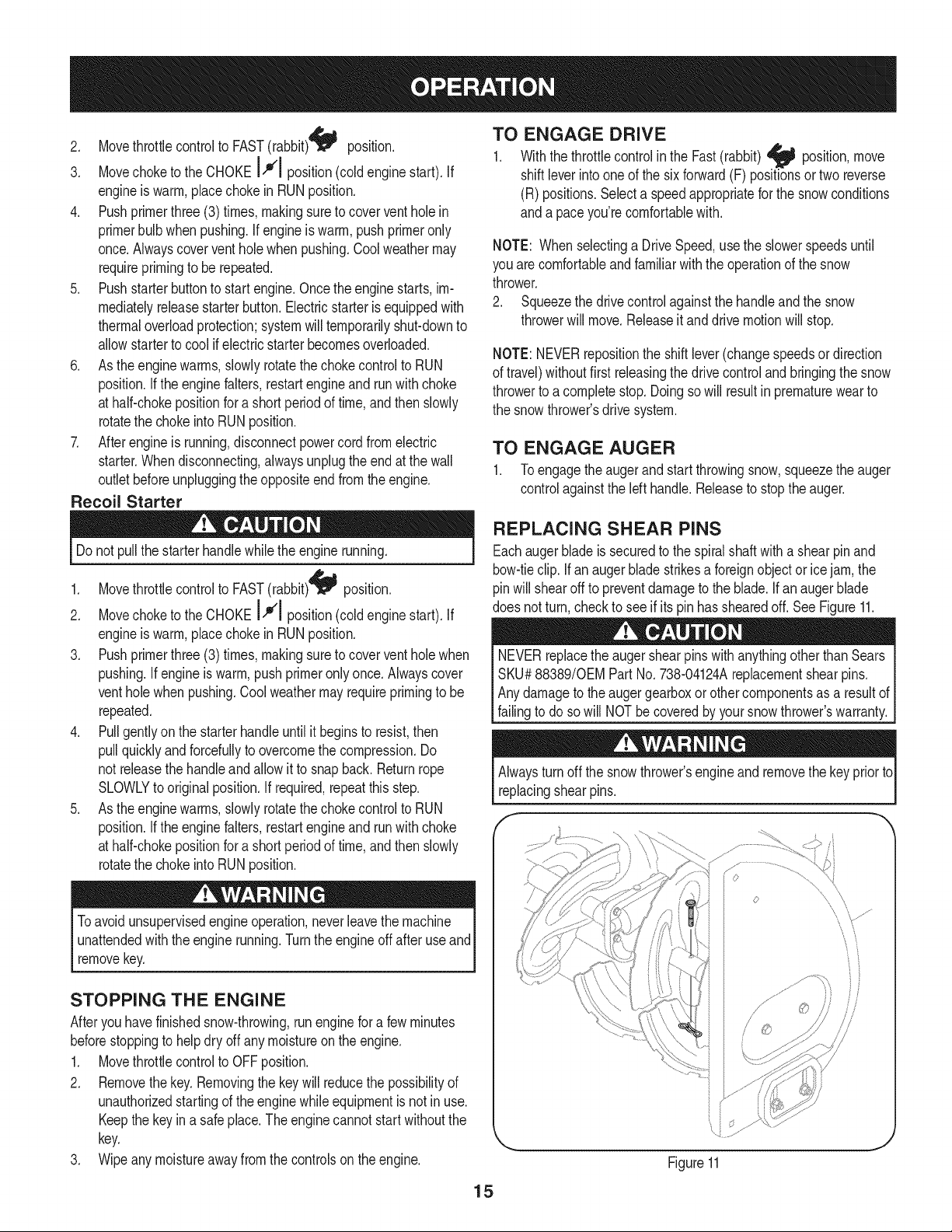
REPLACING SHEAR PINS
Eachauger blade is securedto the spiralshaftwith a shearpinand
bow-tieclip. If an auger bladestrikesa foreignobjector icejam,the
pinwillshearoff to preventdamageto the blade.If an auger blade
does notturn,checkto see if its pin has shearedoff. SeeFigure11.
NEVERreplacethe auger shearpinswith anythingotherthanSears
SKU#88389/0EMPart No.738-04124Areplacementshearpins.
Anydamageto the augergearboxor othercomponentsas a resultof
[fang to doso w NOTbe coveredby yoursnowthrowers warranty.
Alwaysturnoff the snowthrower'sengineandremovethe keypriorto
replacingshearpins.
s ¸......
iJ
Figure11
15
MAINTENANCE SCHEDULE
Beforeperforminganytypeofmaintenance/service,disengageall
controlsand stoptheengine.Waituntilall movingpartshavecometo
acompletestop.Disconnectsparkplugwireandgroundit againstthe
enginetopreventunintendedstarting.Alwayswearsafetyglassesduring
operationor whileperforminganyadjustmentsor repairs.
EachUseandevery5
hours
1st5 hours
Annuallyor 25 hours
Annuallyor 50 hours
Annuallyor 100hours
BeforeStorage
1. Engineoil level
2. Looseor missinghardware
3. Unitand engine.
1. Engineoil
1. Sparkplug
2. Controllinkagesand pivots
3. Wheels
4. Gear shaftand Augershaft
1. Engineoil
1. Sparkplug
1. Fuelsystem
Followthe maintenanceschedulegiven below.This chart describes
serviceguidelinesonly.Usethe ServiceLogcolumnto keeptrackof
completedmaintenancetasks.To locate the nearest Sears Service
Centeror to scheduleservice,simplycontactSearsat
1-800-4-MY-HOME®.
1. Check
2. Tightenor replace
3. Clean
1. Change
1. Check
2. Lubewith light oil
3. Lubewith multipurposeautogrease
4. Lubewith light oil
1. Change
1. Change
1. Runengineuntilit stopsfrom lack
offuel
ENGINE MAINTENANCE
Checking Engine Oil
Beforelubricating,repairing,or inspecting,disengageall controls
Iandstopengine.Wait untilall movingpartshavecometo a complete
_stop.
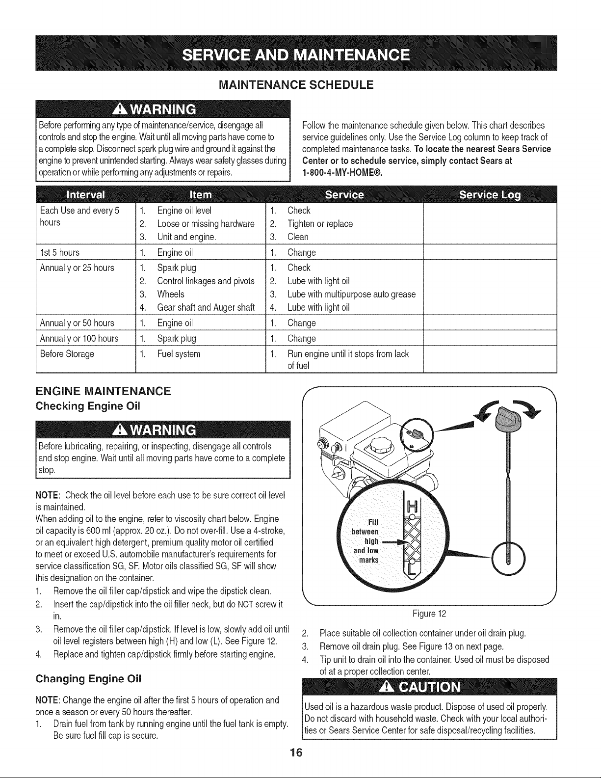
NOTE: Checktheoil levelbeforeeachuseto be surecorrectoil level
is maintained.
Whenaddingoilto the engine,referto viscositychart below.Engine
oilcapacityis 600ml (approx.20 oz.). Donot over-fill.Usea 4-stroke,
oran equivalenthighdetergent,premiumqualitymotoroilcertified
to meetorexceedU.S.automobilemanufacturer'srequirementsfor
serviceclassificationSG, SR MotoroilsclassifiedSG, SFwill show
thisdesignationonthe container.
1. Removethe oil fillercap/dipstickand wipethe dipstickclean.
2. Insertthe cap/dipstickintothe oil filler neck,butdo NOTscrewit
in.
3. Removethe oil fillercap/dipstick.If levelis low, slowlyadd oil until
oil levelregistersbetweenhigh(H) andlow (L). SeeFigure12.
4. Replaceand tighten cap/dipstickfirmlybeforestartingengine.
Changing Engine Oil
NOTE:Changethe engineoil after the first5 hoursof operationand
oncea seasonor every 50 hoursthereafter.
1. Drainfuelfrom tank by runningengineuntilthe fuel tank is empty.
Besurefuel fill cap is secure.
f
1 •
_i!_!iiii_ii!i!jili iiiI iiiii_H
marks
Figure12
2. Placesuitableoil collectioncontainerunderoil drainplug.
3. Removeoil drain plug.See Figure13on nextpage.
4. Tip unit to drainoil intothe container.Usedoil mustbe disposed
of at a propercollectioncenter.
Usedoil isa hazardouswasteproduct.Disposeof usedoil properly.
IDo notdiscardwithhouseholdwaste.Checkwithyour localauthori-
lties or SearsService Centerfor safe disposal/recyclingfacilities.
16
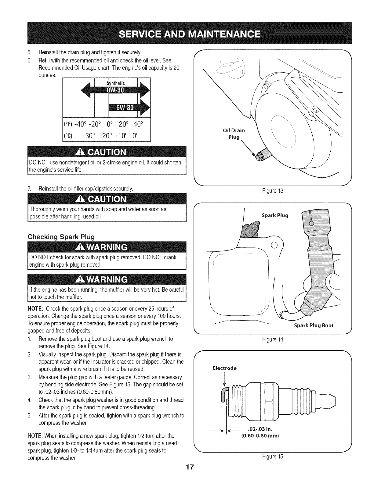
.
6.
Reinstallthe drain plugand tightenit securely.
Refillwiththe recommendedoil andcheckthe oil level.See
RecommendedOil Usagechart.Theengine'soil capacityis 20
ounces.
(%-400 -200 0o 200 400
("c) -300 -200 -10° 0°
DONOTuse nondetergentoilor 2-strokeengineoil. Itcould shorten
the engine'sservicelife.
7. Reinstallthe oilfillercap/dipsticksecurely.
Oil Drain
Plug
Figure13
afterhandling usedoil.
Checking Spark Plug
DO NOTcheckfor sparkwithsparkplugremoved.DO NOTcrank
enginewithsparkplugremoved.
Ifthe enginehasbeenrunning,the mufflerwill bevery hot.Becareful
notto touchthe muffler.
NOTE: Checkthe sparkplugoncea seasonor every 25 hoursof
operation.Changethe sparkplugoncea seasonor every100hours.
Toensureproperengineoperation,the sparkplugmustbe properly
gappedandfreeof deposits.
1. Removethespark plug bootand use a sparkplugwrenchto
removethe plug.See Figure14.
2. Visuallyinspectthe sparkplug.Discardthe spark plug if thereis
apparentwear,or if the insulatoris crackedor chipped.Cleanthe
sparkplugwitha wirebrush if it is to be reused.
3. Measurethe plug gap with a feelergauge.Correctas necessary
by bendingsideelectrode.See Figure15.The gapshouldbeset
to .02-.03inches(0.60-0.80ram).
4. Checkthatthe sparkplug washeris in good conditionandthread
the sparkplugin by handto preventcross-threading.
5. After thespark plug is seated,tightenwitha sparkplugwrenchto
compressthe washer.
NOTE:Wheninstallinga newsparkplug,tighten1/2-turnafterthe
sparkplugseatsto compressthe washer.Whenreinstallinga used
sparkplug,tighten1/8-to 1/4-turnafterthe sparkplugseatsto
compressthe washer.
17
Spark Plug
O
J
Figure14
Electrode
.02-.03 in.
{0.60-0.80 ram)
Figure15
become hotandcan inc.
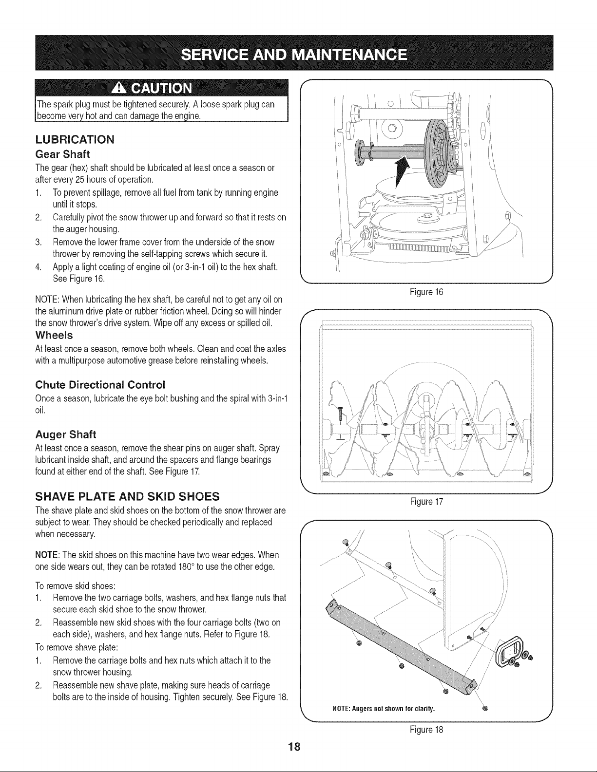
LUBRICATION
Gear Shaft
Thegear(hex)shaft shouldbe lubricatedat leastoncea seasonor
afterevery25 hoursof operation.
1. Topreventspillage,removeall fuel fromtank by runningengine
until it stops.
2. Carefullypivotthe snowthrowerupandforwardso that it restson
theaugerhousing.
3. Removethe lowerframecover fromthe undersideof the snow
throwerby removingthe self-tappingscrewswhich secureit.
4. Applya lightcoatingof engineoil (or 3-in-1oil) to the hexshaft.
SeeFigure16.
NOTE:Whenlubricatingthe hexshaft, be carefulnotto get any oilon
thealuminumdriveplateor rubberfrictionwheel.Doingsowill hinder
the snowthrower'sdrive system.Wipeoff anyexcessor spilledoil.
Wheels
At leastoncea season,removebothwheels.Cleanand coattheaxles
witha multipurposeautomotivegreasebeforereinstallingwheels.
Chute Directional Control
Oncea season,lubricatethe eye boltbushingand thespiralwith3-in-1
oil.
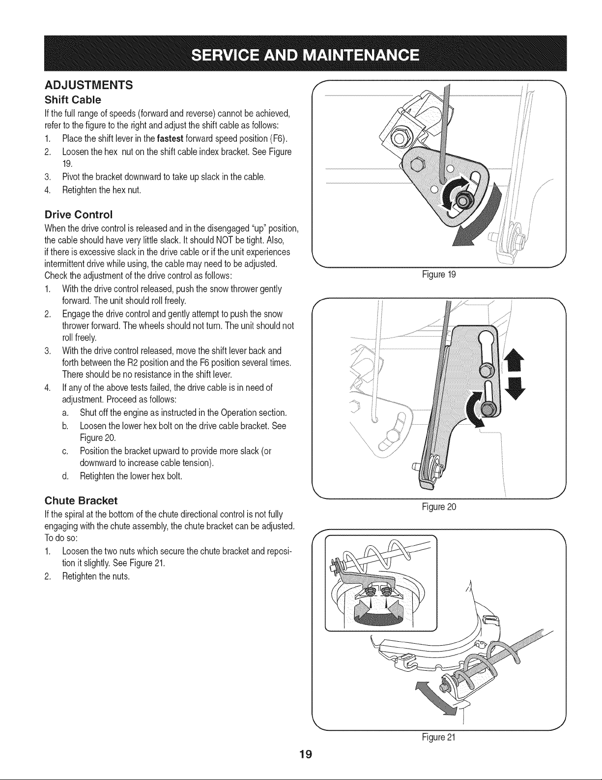
Auger Shaft
At leastoncea season,removethe shearpinson augershaft.Spray
lubricantinsideshaft,andaroundthe spacersandflangebearings
foundat eitherendof the shaft.SeeFigure17.
f
Figure16
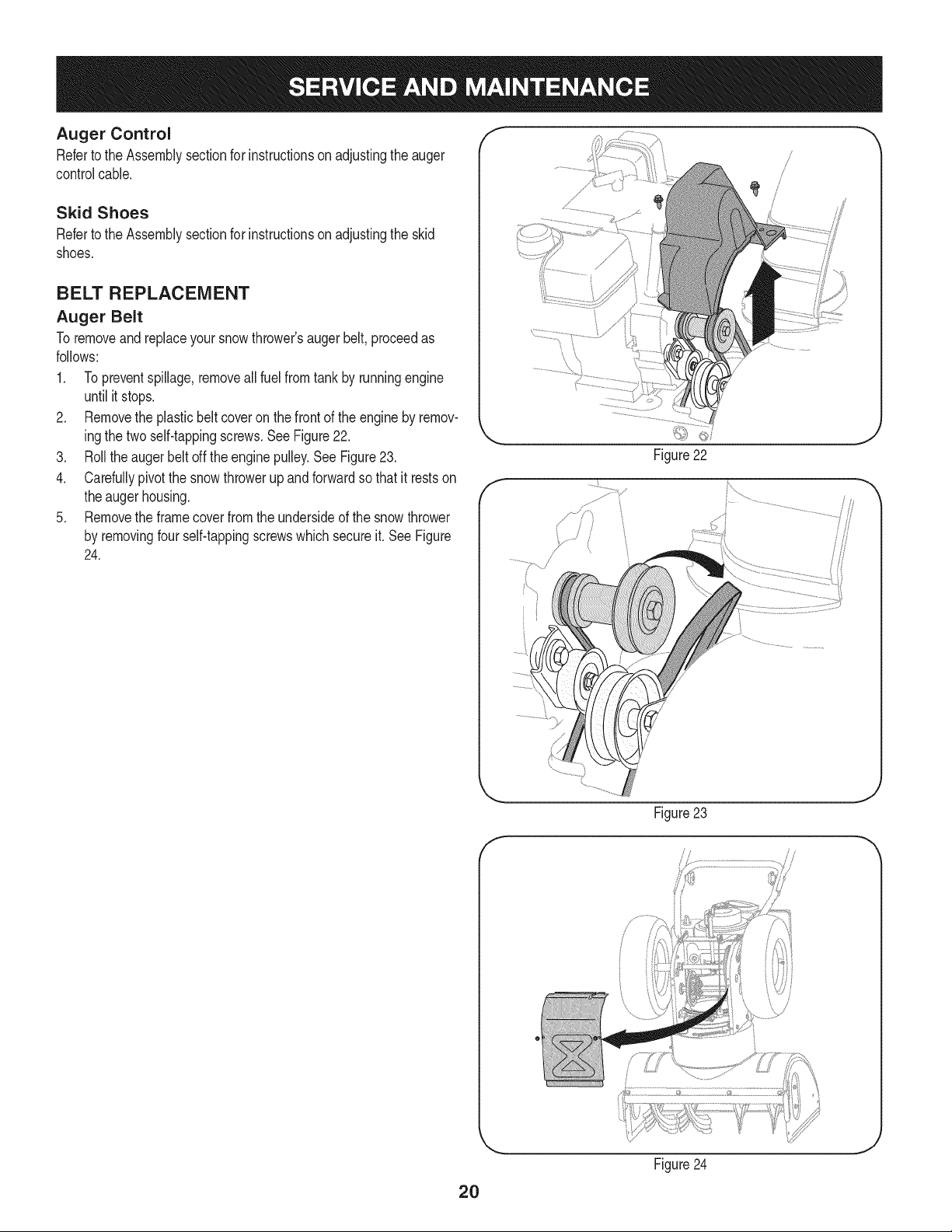
SHAVE PLATE AND SKID SHOES
The shaveplateand skidshoesonthe bottomof the snowthrowerare
subjectto wear.They shouldbe checkedperiodicallyandreplaced
whennecessary.
NOTE:Theskidshoeson this machinehavetwo wearedges.When
onesidewearsout,theycan be rotated1800to usethe otheredge.
To removeskidshoes:
1. Removethe twocarriagebolts,washers,andhex flangenutsthat
secureeachskidshoeto the snowthrower.
2. Reassemblenew skid shoeswith the fourcarriagebolts(twoon
eachside),washers,andhex flangenuts.Referto Figure18.
To removeshaveplate:
1. Removethe carriageboltsand hexnuts whichattachit to the
snowthrowerhousing.
2. Reassemblenew shaveplate,makingsureheadsof carriage
boltsareto the insideof housing.Tightensecurely.SeeFigure18.
Figure17
NOTE:Augers not shown for clarity.
Figure18
/
/
/
/
18
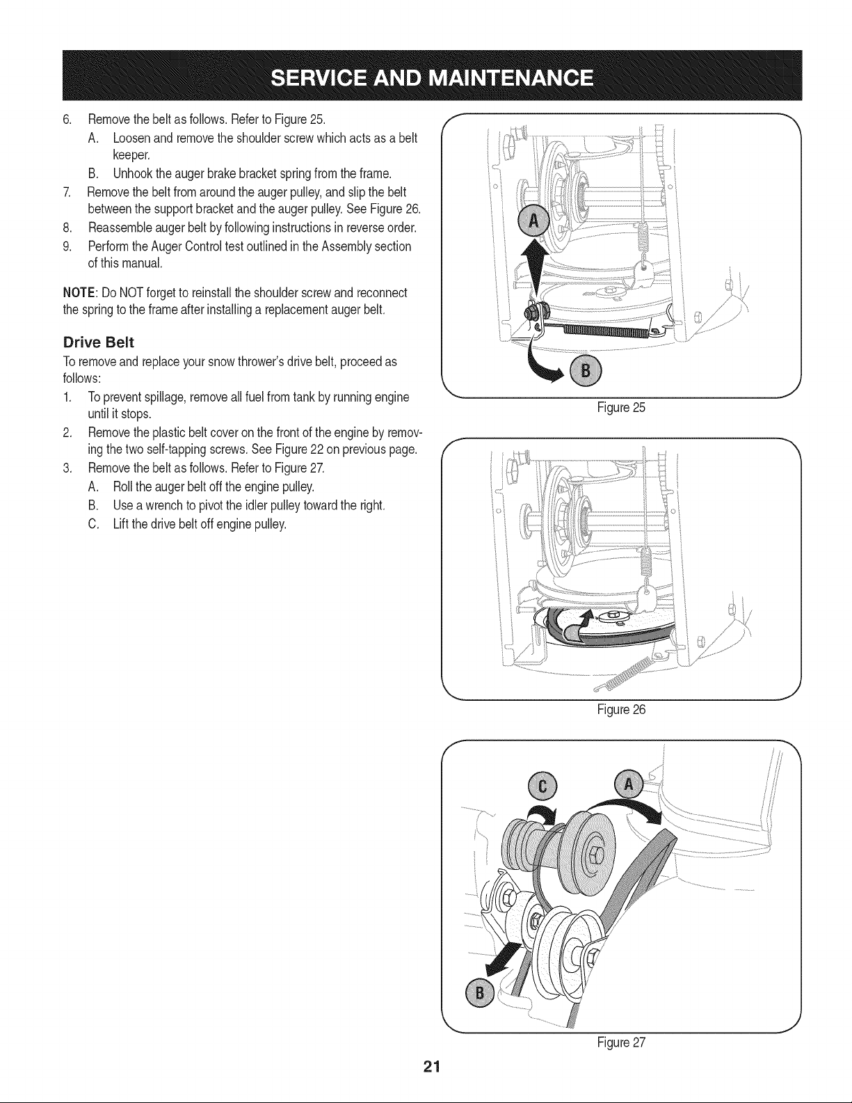
ADJUSTMENTS
Shift Cable
If thefull rangeof speeds(forwardandreverse)cannotbe achieved,
referto the figureto the rightandadjustthe shift cableas follows:
1. Placethe shiftleverin thefastest forward speedposition(F6).
2. Loosenthe hex nuton the shiftcable indexbracket.SeeFigure
19.
3. Pivotthe bracketdownwardto takeupslack inthe cable.
4. Retightenthehex nut.
Drive Control
Whenthedrivecontrolis releasedand in thedisengaged"up"position,
the cableshouldhavevery little slack.It shouldNOTbe tight. Also,
if thereis excessiveslackin thedrive cableor if the unitexperiences
intermittentdrivewhileusing,the cable mayneed to be adjusted.
Checktheadjustmentof the drivecontrolas follows:
1. Withthedrivecontrolreleased,pushthe snowthrowergently
forward.The unitshouldroll freely.
2. Engagethe drivecontroland gently attemptto pushthe snow
throwerforward.Thewheelsshouldnotturn.The unitshouldnot
rollfreely.
3. With thedrivecontrol released,movethe shift leverbackand
forthbetweenthe R2positionandthe F6 positionseveraltimes.
Thereshouldbeno resistancein the shiftlever.
4. If anyof the abovetests failed,the drivecable is in needof
adjustment.Proceedas follows:
a. Shutoff theengineas instructedinthe Operationsection.
b. Loosenthe lowerhexbolt onthe drivecable bracket.See
Figure20.
c. Positionthe bracketupwardto providemoreslack(or
downwardto increasecabletension).
d. Retightenthe lowerhex bolt.
Figure19
f
Chute Bracket
If the spiralat the bottomof the chutedirectionalcontrolis notfully
engagingwiththe chuteassembly,the chute bracketcan beadjusted.
Todo so:
1. Loosenthe two nuts which securethechutebracketandreposi-
tion it slightly.See Figure21.
2. Retightenthe nuts.
f
Figure20
Figure21
19
Auger Control f "_
Referto the Assemblysectionfor instructionson adjustingtheauger
controlcable.
Skid Shoes
Referto the Assemblysectionfor instructionson adjustingthe skid
shoes.
BELT REPLACEMENT
Auger Belt
To removeandreplaceyoursnow thrower'saugerbelt,proceedas
follows:
1. Topreventspillage,removeall fuel fromtank by runningengine
until itstops.
2. Removethe plasticbelt coveron the front of the engineby remov-
ingthe twoself-tappingscrews.See Figure22.
3. Rollthe auger beltoff theenginepulley.See Figure23.
4. Carefullypivotthe snowthrowerupandforwardso that itrestson
theaugerhousing.
5. Removethe framecoverfromthe undersideof the snow thrower
by removingfourself-tappingscrewswhich secureit. See Figure
24.
f
Figure22
J
f
Figure 23
//
2O
Figure24
J
6. Removethebeltasfollows.RefertoFigure25.
A. Loosenandremovetheshoulderscrewwhichactsasabelt
keeper.
B. Unhooktheaugerbrakebracketspringfromtheframe.
7. Removethebeltfromaroundtheaugerpulley,andslipthebelt
betweenthesupportbracketandtheaugerpulley.SeeFigure26.
8. Reassembleaugerbeltbyfollowinginstructionsinreverseorder.
9. PerformtheAugerControltestoutlinedintheAssemblysection
ofthismanual.
NOTE:DoNOTforgettoreinstalltheshoulderscrewandreconnect
thespringtotheframeafterinstallingareplacementaugerbelt.
Drive Belt
Toremoveand replaceyoursnowthrower'sdrivebelt, proceedas
follows:
1. Topreventspillage,removeallfuel fromtankby runningengine
untilit stops.
2. Removetheplasticbelt coveronthe frontof the engineby remov-
ingthe twoself-tappingscrews.See Figure22on previouspage.
3. Removethebelt as follows.Referto Figure27.
A. Rollthe augerbeltoff theengine pulley.
B. Useawrenchto pivotthe idlerpulleytowardthe right.
C. Liftthe drivebelt offenginepulley.
Figure25
Figure26
21
Figure27
4, Carefullypivotthesnowthrowerupandforwardsothatitrestson
theaugerhousing.
5. Removetheframecoverfromtheundersideofthesnowthrower
byremovingtheself-tappingscrewswhichsecureit.Referto
Figure24,
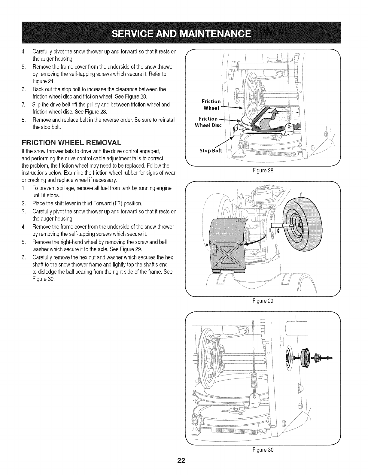
6. Backoutthestopbolttoincreasetheclearancebetweenthe
frictionwheeldiscandfrictionwheel,SeeFigure28,
7. Slipthedrivebeltoffthepulleyandbetweenfrictionwheeland
frictionwheeldisc,SeeFigure28,
8, Removeandreplacebeltinthereverseorder,Besuretoreinstall
thestopbolt.
FRiCTiON WHEEL REMOVAL
Ifthe snowthrowerfailsto drive withthedrivecontrolengaged,
andperformingthe drivecontrolcableadjustmentfailsto correct
the problem,the frictionwheelmayneedto be replaced.Followthe
instructionsbelow.Examinethe frictionwheelrubberfor signsof wear
orcrackingand replacewheelif necessary.
1. Topreventspillage,removeall fuel fromtank by runningengine
until it stops.
2. Placethe shiftleverin third Forward(F3) position.
3. Carefullypivotthe snowthrowerupandforwardso that it restson
theaugerhousing.
4. Removethe framecoverfromthe undersideof the snow thrower
by removingthe self-tappingscrewswhich secureit.
5. Removethe right-handwheelby removingthe screwandbell
washerwhichsecureit to theaxle.See Figure29.
6. Carefullyremovethe hexnut andwasherwhichsecuresthe hex
shaftto the snowthrowerframeand lightlytap the shaft'send
to dislodgethe ball bearingfrom the rightsideof theframe.See
Figure30.
i° i
Friction ;,
Wheel
Stop Bolt
Figure28
/ ii
J
Figure29
f
Figure30
J
22
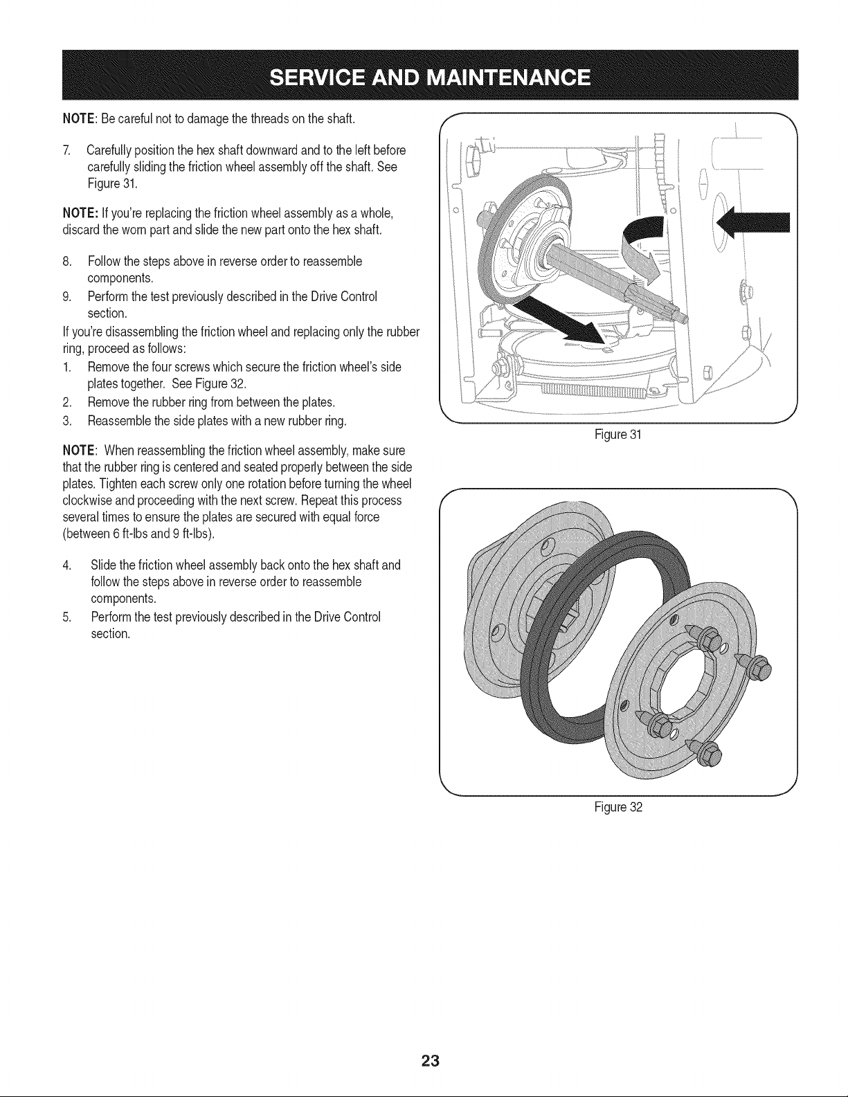
NOTE:Becarefulnot to damagethe threadson the shaft,
7. Carefullypositionthe hexshaftdownwardand to the left before
carefullyslidingthe frictionwheelassemblyoff the shaft. See
Figure31.
NOTE: Ifyou'rereplacingthe frictionwheelassemblyas a whole,
discardthe wornpartand slidethe newpart ontothe hexshaft.
8. Followthe stepsabovein reverseorderto reassemble
components.
9. Performthetest previouslydescribedinthe DriveControl
section.
If you'redisassemblingthefrictionwheeland replacingonly the rubber
ring,proceedas follows:
1. Removethefour screwswhich securethe frictionwheel'sside
platestogether. SeeFigure32.
2. Removethe rubberringfrombetweenthe plates.
3. Reassemblethe side plateswith a newrubberring.
NOTE: Whenreassemblingthe frictionwheelassembly,makesure
thatthe rubberringis centeredand seatedproperlybetweenthe side
plates.Tighteneachscrewonlyone rotationbeforeturningthe wheel
clockwiseand proceedingwiththe nextscrew.Repeatthisprocess
severaltimes toensurethe platesaresecuredwithequalforce
(between6 ft-lbsand 9 ft-lbs).
Figure31
4. Slide the frictionwheelassemblybackonto the hexshaftand
followthestepsabovein reverseorder to reassemble
components.
5. Performthe testpreviouslydescribedin the DriveControl
section.
t j
Figure32
23
Ifthe snowthrowerwillnot be usedfor30 daysor longer,or if it is the end of the snowseasonwhenthe lastpossibilityof snowis gone,the
equipmentneedsto bestoredproperly.Followstorageinstructionsbelowto ensuretop performancefromthe snowthrowerfor manymoreyears.
PREPARING ENGINE
Enginesstoredover30 days need to bedrainedof fuel to prevent
deteriorationandgumfromforminginfuel systemor onessential
carburetorparts.If thegasolinein yourenginedeterioratesduring
storage,youmay needto havethe carburetor,andotherfuel system
components,servicedor replaced.
1. Removeall fuel fromtank by runningengineuntil it stops.Donot
attemptto pourfuel fromthe engine.
2. Changethe engineoil.
3. Removesparkplugandpourapproximately1oz.(30 rnl) of clean
engineoil intothe cylinder.Pullthe recoilstarterseveraltimesto
distributetheoil, and reinstallthe sparkplug.
4. Cleandebrisfromaroundengine,andunder,around,andbehind
muffler.Applya lightfilmof oilon anyareasthat are susceptible
to rust.
• Storeina clean,dry and wellventilatedareaawayfromanyap-
pliancethat operateswith a flame or pilotlight,suchas a furnace,
waterheater,or clothesdryer.Avoidany areawitha spark
producingelectricmotor,or wherepowertoolsareoperated.
Neverstoresnowthrowerwithfuel intank indoorsor inpoorlyventi-
latedareas,wherefuel fumesmay reachan openflame,spark or pilol
lightas ona furnace,waterheater,clothesdryer or gas appliance.
• If possible,avoidstorageareaswithhighhumidity.
• Keepthe enginelevelin storage.Tiltingcan causefuel oroil
leakage.
PREPARING SNOW THROWER
Whenstoringthe snowthrowerin an unventilatedormetalstor-
age shed,careshouldbe taken to rustprooftheequipment.Using
a light oil or silicone,coat theequipment,especiallyanychains,
springs,bearingsand cables.
• Removealldirt fromexteriorof engineandequipment.
• Followlubricationrecommendations.
• Storeequipmentin a clean,dry area.
• Inflatethe tiresto the maximumPSi. Referto tiresidewall.
24
Enginefailsto start
Enginerunningerratically/
inconsistentRPM(huntingor
surging)
Excessivevibration
Lossof power
Unitfailsto propelitself
Unitfailsto dischargesnow
1. Chokecontrolnot in CHOKEposition.
2. Sparkplugwire disconnected.
3. Faultysparkplug.
4. Fueltank emptyor stalefuel.
5. Enginenot primed.
6. Keynot inserted.
7. Extensioncordnot connected(when
usingelectricstartbutton,on modelsso
equipped).
1. Enginerunningon CHOKE.
2. Stalefuel.
3. Wateror dirt in fuel system.
4. Over-governedengine.
1. Loosepartsor damagedauger.
1. Sparkplugwire loose.
2. Gascap vent hole plugged.
1. Drivecable in need of adjustment.
2. Drivebelt looseor damaged.
3. Wornfrictionwheel.
1. Chuteassemblyclogged.
2. Foreignobjectlodgedin auger.
3. Augercablein needof adjustment.
4. Augerbelt looseordamaged.
5. Shearpin(s) sheared.
1. Chuteassembledincorrectly.
1. Movechokecontrolto CHOKEposition.
2. Connectwireto sparkplug.
3. Clean,adjustgap,or replace.
4. Filltank with clean,freshgasoline.
5. Primeengineas instructedin the OperationSection.
6. Insertkeyfully intothe switch.
7. Connectoneendof the extensioncordto the electric
starteroutletandthe otherendto a three-prong
120-volt,grounded,ACoutlet.
1. Movechokecontrolto RUNposition.
2. Filltank with clean,freshgasoline.
3. Drainfueltank by runningengineuntil it stops. Refill
withfreshfuel.
4. ContactyourSearsParts & RepairCenter.
1. Stopengineimmediatelyand disconnectsparkplug
wire.Tightenall boltsand nuts.Ifvibrationcontinues,
haveunit servicedbya SearsParts& RepairCenter.
1. Connectandtightensparkplugwire.
2. Removeiceand snowfrom gascap. Becertainvent
holeis clear.
1. Adjustdrivecontrolcable. Referto Serviceand
Maintenancesection.
2. Replacedrive belt. Referto Serviceand Mainte-
nancesection.
3. Havefrictionwheelreplacedat a SearsParts &
RepairCenter.
1. Stopengineimmediatelyand disconnectsparkplug
wire.Cleanchuteassemblyandinsideof auger
housingwith clean-outtoolor a stick.
2. Stopengineimmediatelyand disconnectsparkplug
wire.Removeobjectfrom augerwith clean-outtool
ora stick.
3. Adjustaugercontrolcable. Referto Assembly
section.
4. Replaceauger belt. Referto Serviceand Mainte-
nancesection.
5. Replacewith newshearpin(s).
Chutefailsto easilyrotate180 1. Disassemblechutecontroland reassembleas
degrees directedinthe Assemblysection.
NEED HORE HELP?
Yot,Fttfind. th_ answer a!ld mo_e on ma_age_y_ifeocom _ for free]
Find this and att your other product manua[s ontine.
Get answers from our team of home experts.
Get a personalized maintenance p[an for your home.
Find information and tools to he[p with home projects.
managemylife
b_e'_g_t_/_eyeu by Sea_s
25
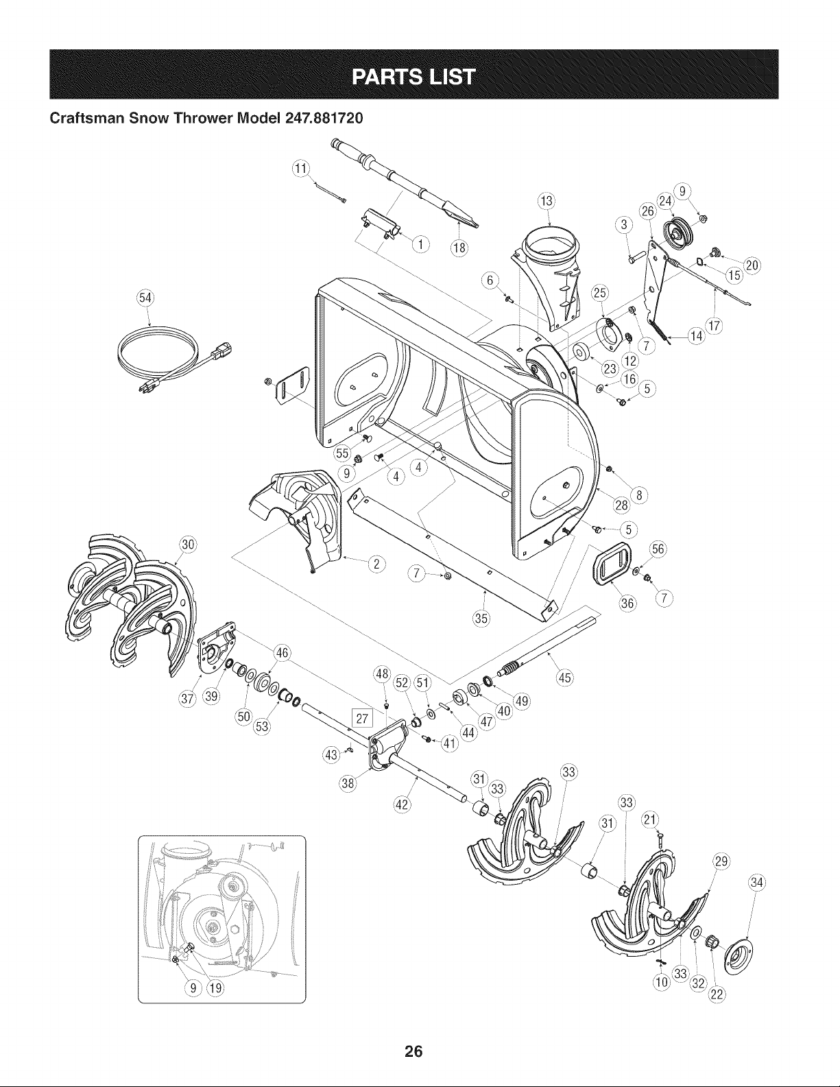
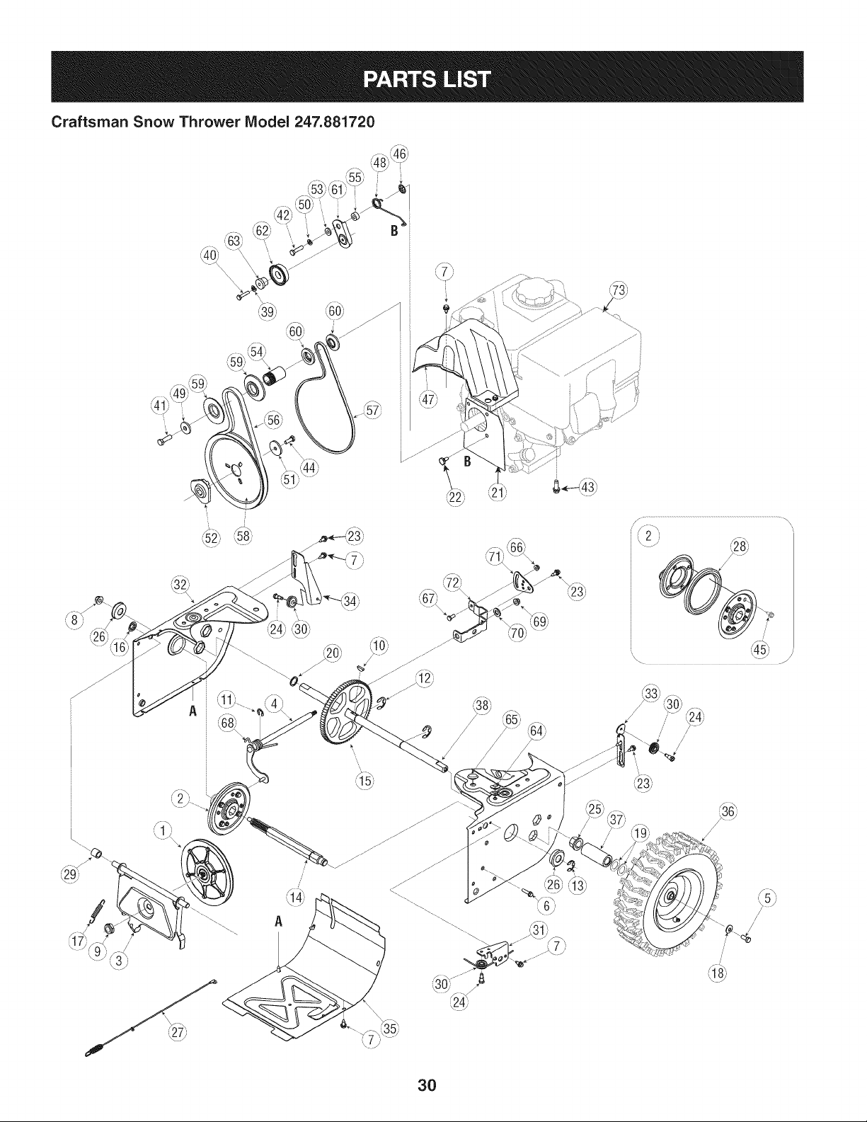
Craftsman Snow Thrower IViodel 247.881720
I
i
/
,// ///'
/
26
Craftsman Snow Thrower IViodel 247.881720
D = 0 0
731-2635 Snow RemovalToolMount
2. 684-04057A-0637 ImpellerAssembly,12"Dia.
3. 710-0347 HexScrew,3/8-16, 1.75,Gr5
4. 710-0451 Bolt,Carriage,5/16-18,.750Grl
5. 710-04484 Screw, 5/16-18,0.750
6. 710-0703 Screw,Carriage,1/4-20,.750,Gr5
7. 712-04063 Nut,FlangeLock,5/16-18,Nylon
8. 712-04064 Nut,FlangeLock,1/4-20,Nylon
9. 712-04065 Nut,FlangeLock,3/8-16, Nylon
10. 714-04040 CotterPin, Bow-tie
11. 725-0157 Cable,Tie, 3/16x .05 x 7.4
12. 926-04012 Nut,Push-on,.25Dia
13. 731-04705D Chute,Adapter5" Dia
14. 732-04460 Spring,Extension,.38 ODx 4.59
15. 736-0174 Washer,Wave,.625x .885x .015
16. 736-0242 Washer,Bell,.340x .872x .060
17. 946-04230A ClutchCable,Auger,47.23"
18. 931-2643 Snow RemovalTool
19. 738-0143 Screw,Shoulder,.498x .34,3/8-16
20. 938-0281 Screw,Shoulder,.625x .17,3/8-16
21. 738-04124A ShearPin,.25x 1.50
22. 941-0245 Bearing,Hex Flangex .75 ID
23. 941-0309 Bearing,Ball,.75IDx 1.85OD
24. 756-04224 FlatPulley,Idler, 2.75OD
25. 790-00075 Housing,Bearing,1.85ID
26. 790-00080B Bracket,AugerIdlerw/Brake
27. 918-04171B GearboxAssembly,Auger,24"
28. 684-04265-4044 HousingAssembly,Auger24"
684-04107-0637
30. 684-04108-0637
31. 731-04870
32. 736-0188
33. 741-0493A
34. 790-00087A-0637
35. 790-00120-4044
36. 731-06439
37. 918-0123A
38. 918-0124A
39. 921-0338
40. 741-0662
41. 710-0642
42. 711-04285
43. 914-0161
D = O
SpiralAssembly,LH
SpiralAssembly,RH
Spacer,1.25OD x .75 ID x 1.00
Washer,Flat,.76x 1.49x .06
Bushing,Flange,.80 IDx .91OD
Housing,1"Hex Bearing
ShavePlate,2.25x 23.66
SlideShoe
Housing,Gearbox,RH
Housing,Gearbox,LH
Seal,Oil, .750x 1.00x .125
Bearing,Flange,.75x 1.0x .59
Screw,Self-tapping,1/4-20,0.750
Axle,Auger,24"
Key,Hi-pro3/16x 5/8
44. 715-04021 Pin,Dowel,.25OD x 1.2
45. 917-04126 Shaft,Worm.75OD
46. 917-04861 Gear,Worm20T
47. 718-04071 Collar,Thrust
48. 721-0325 Plug,1/4x .437
49. 721-0327 Seal,Oil, .75x 1 x .131
50. 936-0351 Washer,Flat,.760IDx 1.50D
51. 736-3084 Washer,Flat,.51x 1.12
52. 741-0663 Bearing,Flange,.75x 1.0x .925
53. 741-0661A Bearing,Flange,.75x 1.00x .975
54. 929-0071A ExtensionCord, 110V
55. 710-0276 Screw,Carriage,5/16-18x 1.00
56. 936-0159 Washer,Fiat,.349x .879x .063
27
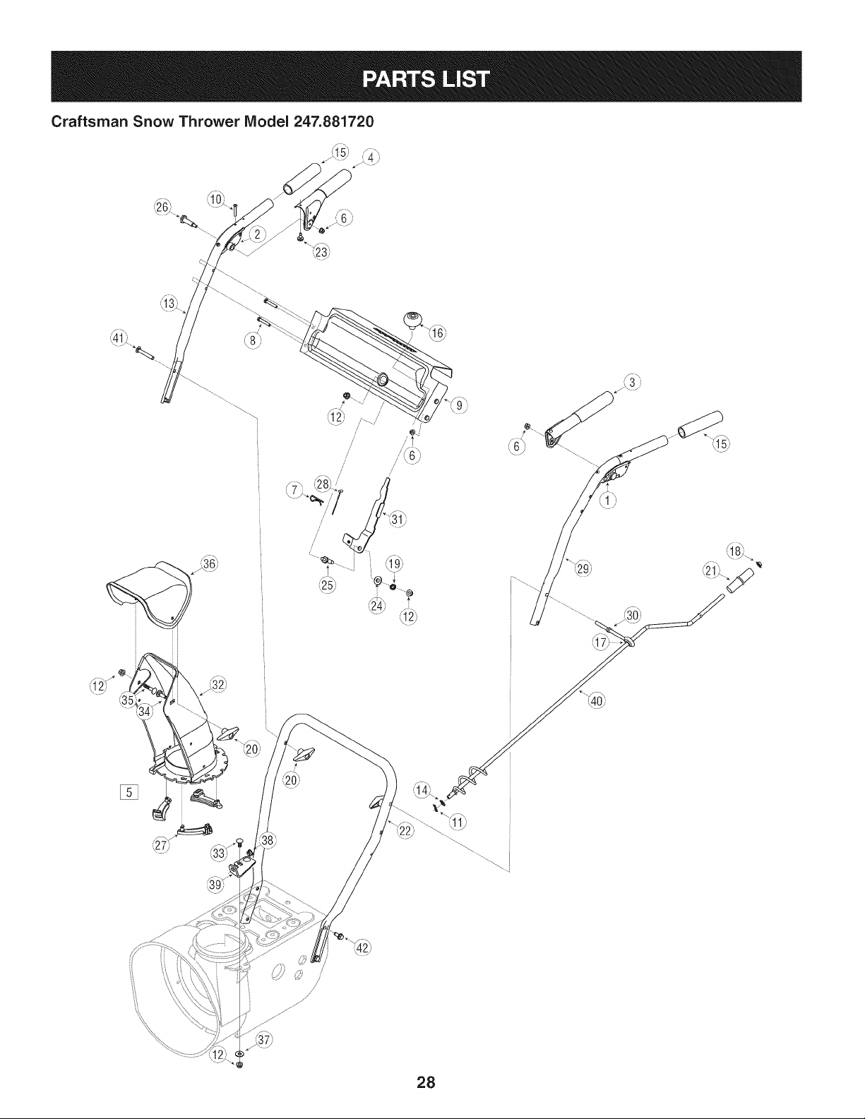
Craftsman Snow Thrower Model 247.881720
[]
=\!Sj)
28
Craftsman Snow Thrower IViodel 247.881720
D = " 0
631-04133A HandleAssembly,ClutchLock,LH
2. 631-04134B HandleAssembly,ClutchLock,RH
3. 684-04105B HandleAss'y,Engage,LH
4. 684-04106C HandleAss'y,Engage,RH
5: J631-04131B JChute, Lower(Inc/_Ref.# 27,Qty.3)
6. 712-04064 Nut,FlangeLock,1/4-20
7. 914-0145 ClickPin
8. 710-0606 Screw,1/4-20x 1.50
9. 790-00219-4044 Panel,Handle,(no cutout)
10. 710-1233 Screw,Machine,#10-24,1.375
11. 914-0104 Pin,Cotter,.072x 1.13
12. 712-04063 Nut,FlangeLock,5/16-18,Nylon
13. 749-04190A-0637 Handle,Upper,RH
14. 936-0185 Washer,Fiat,.375x .738x .063
15. 720-0274 Grip,1.0ID x 5.0
16. 720-04039 Knob,Shift,Black
17. 735-0234 Grommet,.44 IDx .94 ODx .50
18. 926-0100 Cap,Push,3/8 Rod
19. 732-0193 Spring,.39 x .60 x .88
20. 920-0284 Knob,5/16-18,Black
21. 720-0201A CrankKnob,1.0Dia.x 3.2, Black
D = W O
749-04138A-0637 Handle,Lower
23. 935-0199A Bumper,Rubber,.62 ODx .22
24. 736-0262 Washer,Fiat, .385x .870x .092
25. 738-04118 Bolt,Shoulder,5/16-18x 0.905
26. 738-04348 Screw,Shoulder,.43x 1.3,1/4-20
27. 731-04869A Chute,FlangeKeeper
28. 946-04397A Cable,SpeedSelector
29. 749-04191A-0637 Handle,Upper,LH
30. 747-04263 EyeBolt,ChuteCrank
31. 790-00313-0637 Shift Lever
32. 731-04912B Chute,Lower,5.0 Dia.
33. 710-0276 Bolt, Carriage,5/16-18,1.0
34. 710-04071 Bolt,Carriage,5/16-18,1.0
35. 710-0451 Bolt, Carriage,5/16-18,.750
36. 731-04426A Chute,Upper,w/Label
37. 936-0159 Washer,.349x .879x .063
38. 941-0475 Bushing,Plastic,.380
39. 784-5647-0637 Bracket,ChuteCrank
40. 684-04104-0637 CrankAssembly,Chute
41. 710-0449 Screw,Carriage,5/16-18,2.25
42. 710-04484 Screw,5/16-18,2.25, Gr5
29
Craftsman Snow Thrower IViodel 247.881720
A
/
/
/
/
A
3O
Craftsman Snow Thrower IViodel 247.881720
I = 0 0
656-04055 DiscAssembly,FrictionWheel
2. 684-04153 FrictionWheelAssembly,5.50D
3. 684-04154B-0637 SupportBracket,FrictionWheel
4. 684-04156A ShiftAssembly,Rod
5. J 710-0627 J HexScrew,5/16-24,.750,Gr5
6. 710-0788 Screw,1/4-20,1.000
7. 710-1652 Screw,1/4-20x .625
8. 712-04065 Nut,FlangeLock,3/8-16, Nylon
9. 712-0417A Nut,Flange,5/8-18
10. 914-0126 Key,Hi Pro,3/16x 3/4 Dia.
11. 916-0104 E-ring,.500 Dia.
12. 716-0136 E-ring,Retaining, .875Dia.
13. 916-0231 E-ring,.750Dia.
14. 917-04209A HexShaft,.8125,7-Tooth
15. 917-04230A Gear,80-Tooth
16. .726-0221 Speed Nut,.500
17. 932-0264 ExtensionSpring
18. 736-0242 Washer,Bell,.340x .872x .060
19. 936-0287 Washer,Flat,.793x 1.24x .060
20. 736-04161 Washer,Flat,.75x 1.00x .060
21. 790-00289A-0637 Plate,Cover
22. 738-04439 ShoulderScrew
23. 738-04184A Screw,Shoulder,.37x .105,1/4-20
24. 738-0924A Screw,1/4-28,.375
25. 941-0245 Bearing,Hex Flangex .75 ID
26. 941-0563 Bearing,Ball,17x 40 x 12
27. 946-04229B ClutchCable,Wheel,44.95"
28. 935-04054 Rubber,FrictionWheel,5.50D
29. 748-0190 Spacer,.508ID x .75OD x .68
30. 756-0625 Roller,Cable
31. 790-00096-0637 FrontGuideBracket,AugerCable
32. 790-00180A-4044 Frame
33. 790-00206A-0637 Guide Bracket,AugerCable
34. 790-00207C GuideBracket,DriveCable
35. 790-00316-0637 Cover,Frame
36. 634-04167A-0911 LHWheelAssembly
634-04168A-0911 RHWheelAssembly
D = O e
731-04873 Spacer,1.25x .75x 3.0
38. 938-04168 Axle,.75x 22"
39. 736-0329 Washer,Lock, 1/4
40. 710-0809 Hex Screw,1/4-20,1.25,Gr5
41. 710-0191 Hex Screw,3/8-24,1.25,Gr8
42. 710-0672 Hex Screw,5/16-24,1.25,Gr5
43. 710-0654A Screw,Seres,3/8-16, 1.00
44. 710-1245B HexScrew,5/16-24,.875,Gr8
45. 710-0896 Screw,1/4-20x .625
46. 926-04012 Nut, Push-on,.25 Dia.
47. 731-04792A Cover,Belt
48. 732-04308A Spring,Torsion,.850 ID x .354
49. 736-0247 Washer,Flat, .406x 1.25x .157
50. 936-0119 Washer,Lock.3125
51. 736-0505 Washer,Flat, .34x 1.50x .150
52. 748-04053A Pulley,Adapter,.75 Dia.
53. 748-04112B Spacer,Shoulder,.317x .50 x .102
54. 750-04303 Spacer,.875IDx 1.185OD
55. 750-04477A Spacer,.340x .750x .360
56. 954-04050 Belt,AugerDrive
57. 954-04260 Belt,WheelDrive
58. 756-04109 Pulley,AugerDrive,8.1x .5
59. 756-04113 Pulley,Half,V x 2.600 OD
60. 756-04252 Pulley,Half,3/8-V x 1.7160OD
61. 790-00208C Idler Bracket,Wheel Drive
62. 684-04169 Idler PulleyAssembly
63. 750-04571 Spacer,Shoulder,.26x .79x .538
64. 735-04099 Plug,3/8 ID
65. 735-04100 Plug,1/2 ID
66. 712-04064 Nut, FlangeLock,1/4-20,Nylon
67. 710-0751 Hex Screw,1/4-20,.620,Gr5
68. 732-04311A Spring,Torsion,.750ID x .968
69. 712-04063 Nut, FlangeLock,5/16-18,Nylon
70. 936-3015 Wash.,Flat,.469x .875x .105
71. 790-00217A-0637 PivotBracket,SpeedSelector
72. 790-00218A-0637 Shift Bracket,SpeedSelector
73. 952Z265-SUA ReplacementEngine
31
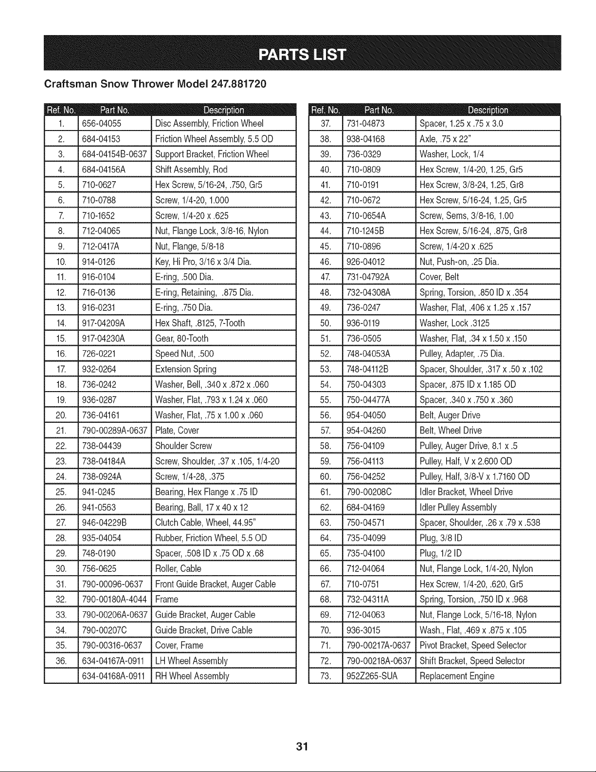
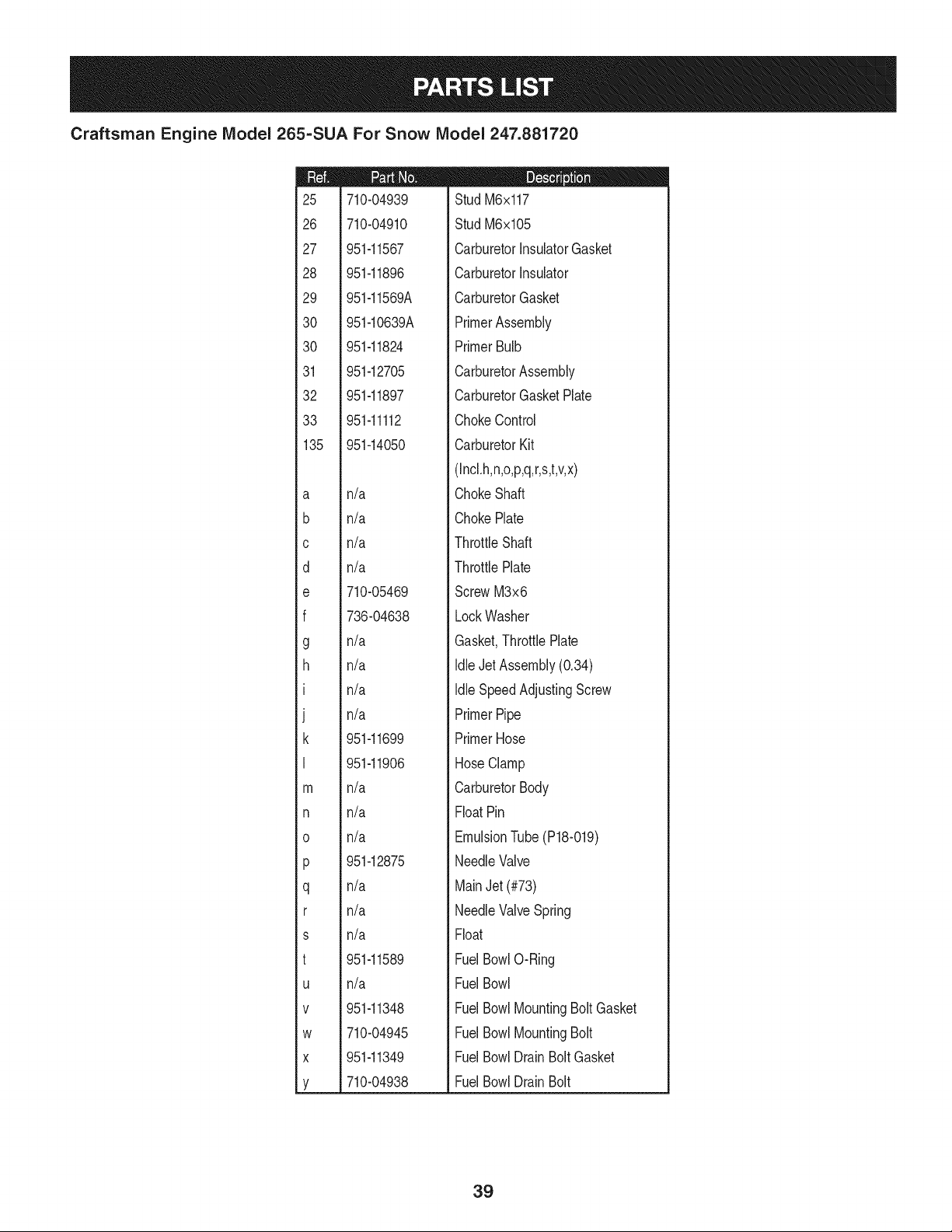
Craftsman Engine Model 265=SUA For Snow Model 247.881720
24
23
m
I
i
i19
!
i
120
i
i
i
i20
!
!
i
121
i
i
122
i
i
i
i23
!
i
i
124
i
951-11282
710-05001
751-14190
951-11289
712-04214
710-04915
951-10642B
m = I! O
MufflerAssembly
StudM8x36
MufflerStud Kit
ExhaustPipe Gasket
Nut,M8
Bolt M6x12
MufflerShield
32
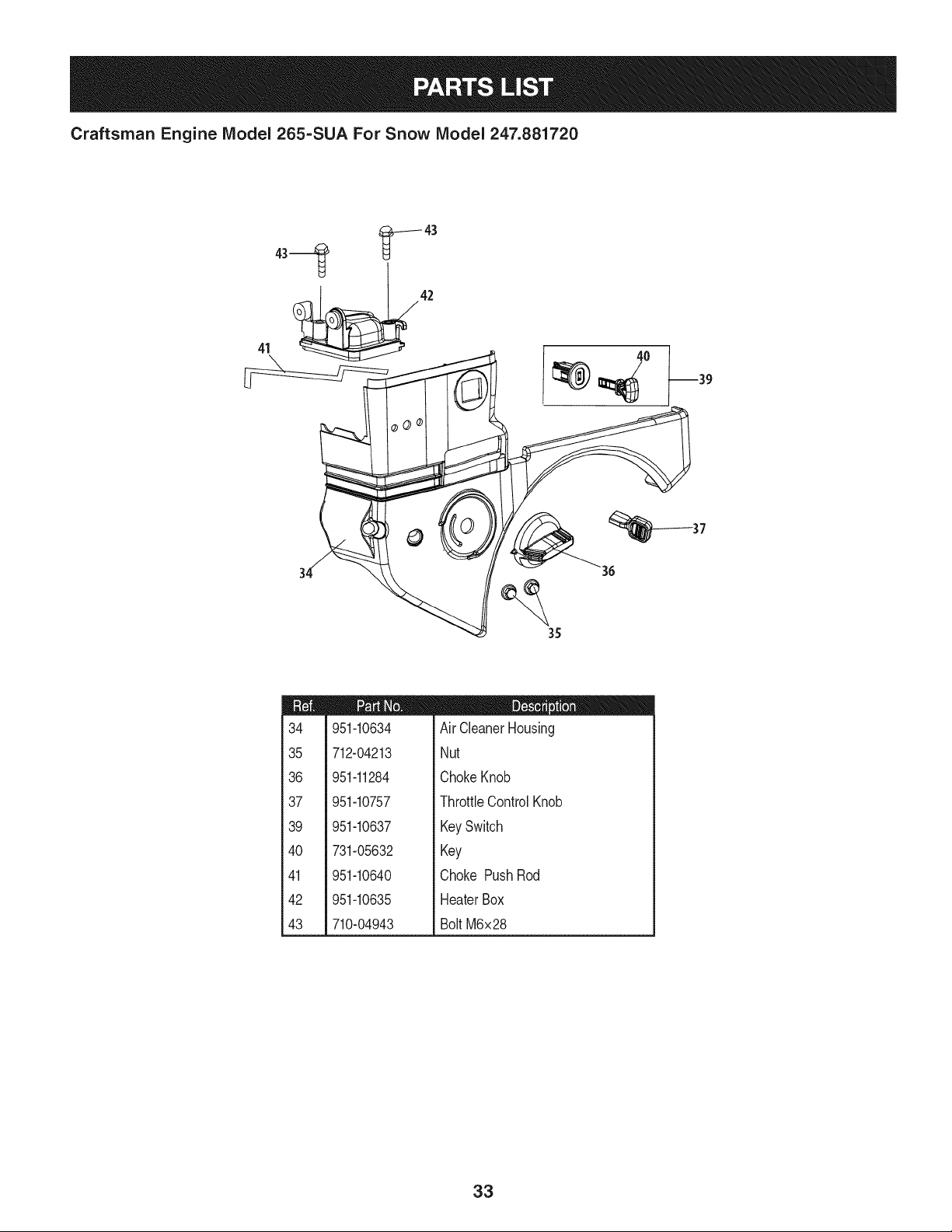
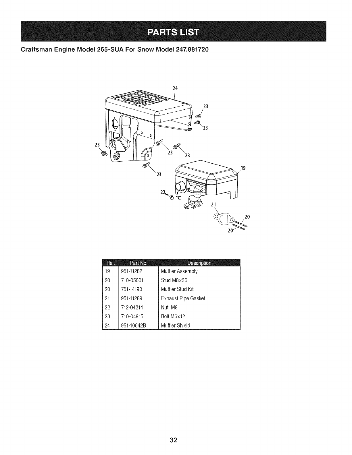
Craftsman Engine Model 265=SUA For Snow Model 247.881720
41 _42
°0
37
35
m
34
35
36
37
39
4O
41
42
43
951-10634
712-04213
951-11284
951-10757
951-10637
731-05632
951-10640
951-10635
710-04943
D = O O
Air CleanerHousing
Nut
ChokeKnob
ThrottleControlKnob
KeySwitch
Key
Choke PushRod
HeaterBox
Bolt M6x28
33
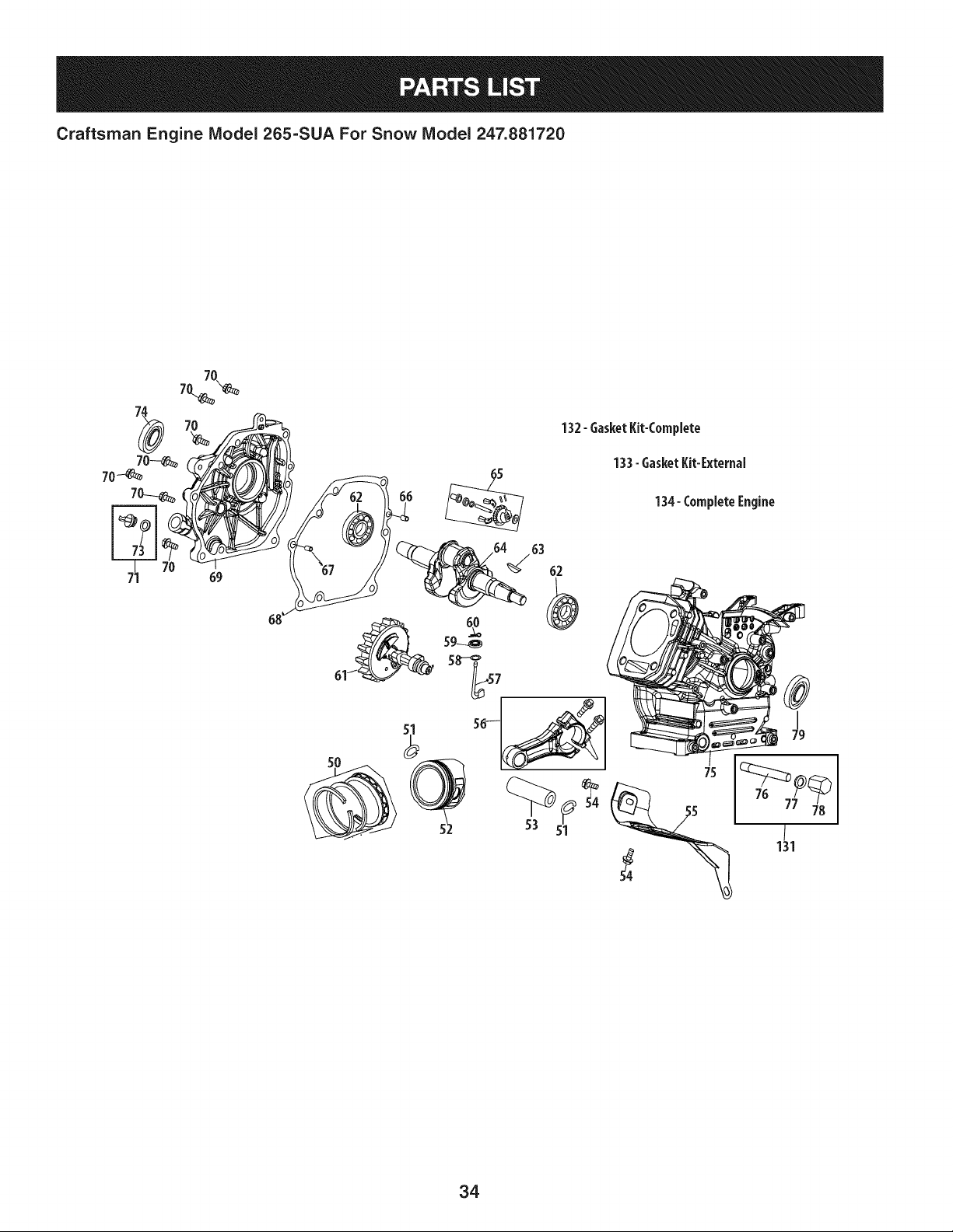
Craftsman Engine Model 265=SUA For Snow Model 247.881720
132- 6asket Kit-Complete
133- 6asket Kit-External
134-CompleteEngine
63
62
34

Craftsman Engine IViodel 265=SUA For Snow IViodel 247.881720
m
5O
51
52
53
54
55
56
57
58
59
6O
61
62
63
64
65
66
67
68
69
951-11688
951-11632
951-11900
951-11901
710-04915
951-11113
951-11573
951-14053
736-04461
951-11902
714-04078
951-11575
951-11369
951-10307
951-11247A
951-11576
715-04092
715-04096
951-11371
951-12125
951-11246
D = O
PistonRingSet
PistonPinSnapRing
Piston
PistonPin
Bolt M6x12
Air Shield
ConnectingRodAssembly
GovernorArm Shaft
Washer5.2xl.9
GovernorSeal
CotterPin
CamshaftAssembly
RadialBallBearing,6205
WoodruffKey
CrankshaftKit
(Incl.62-64,74,79)
GovernorGear/ShaftAssembly
DowelPin7x14
DowelPin9x14
CrankcaseCoverGasket
CrankcaseCover
CrankcaseCoverKit
(Incl.62,68-74)
m
7O
71
73
74
75
76
77
78
79
131
132
133
134
710-04932
951-11283
951-11577
951-11368
951-11248A
951-11062B
951-11350
736-04440
710-04906
951-11370
951-10641
951-11061A
951-10661B
952Z265-SUA
D = O O
Bolt M8x32
Oil FillPlugAssembly
O-Ring15.8x2.5
OilSeal,25x41.25x6
CrankcaseKit
(Incl.59,62,74,75,79)
ShortBlockAssembly
(Incl.4,21,27-29,32,44,
46,47,80-53,56-79)
Oil DrainPipeAssy.
Washer10x16x1.5
Oil DrainPlug
OilSeal25x41.25x6
Oil DrainAssembly
GasketKit- Complete
(Incl.4,21,27-29,32,44,
58,59,68,74,77,79)
GasketKit- External
(Incl.4,21,27-29,32,77)
CompleteEngine
35
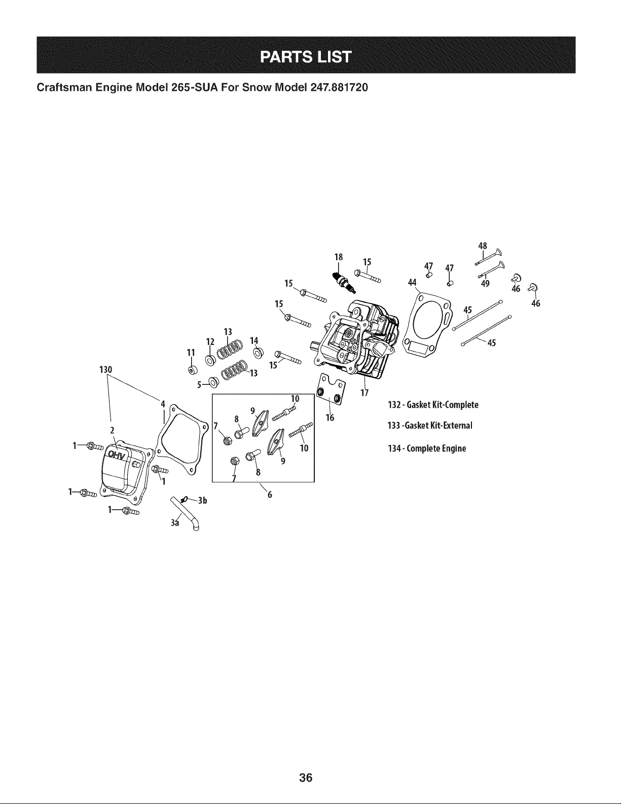
Craftsman Engine Model 265=SUA For Snow Model 247.881720
48
15 44 _)
13
u_ _ _'45
10
\6
17
132-GasketKit-Complete
133-GasketKit-External
134-CompleteEngine
36
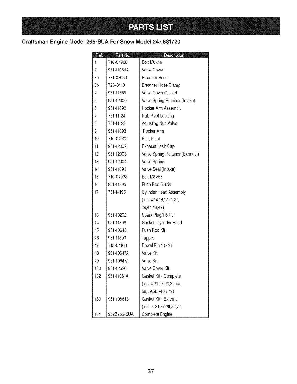
Craftsman Engine IViodel 265=SUA For Snow IViodel 247.881720
m
1
2
3a
3b
4
5
6
7
8
9
10
11
12
13
14
15
16
17
18
44
45
46
47
48
49
130
132
133
134
710-04968
951-11054A
731-07059
726-04101
951-11565
951-12000
951-11892
751-11124
751-11123
951-11893
710-04902
951-12002
951-12003
951-12004
951-11894
710-04933
951-11895
751-14195
951-10292
951-11898
951-10648
951-11899
715-04108
951-10647A
951-10647A
951-12626
951-11061A
951-10661B
952Z265-SUA
D = W O
Bolt M6x16
ValveCover
BreatherHose
BreatherHose Clamp
ValveCoverGasket
ValveSpring Retainer(Intake)
RockerArmAssembly
Nut, PivotLocking
AdjustingNut,Valve
RockerArm
Bolt,Pivot
ExhaustLashCap
ValveSpring Retainer(Exhaust)
ValveSpring
ValveSeal (Intake)
Bolt M8x55
PushRodGuide
CylinderHeadAssembly
(Incl.4-14,16,17,21,27,
29,44,48,49)
SparkPlug/F6Rtc
Gasket,CylinderHead
PushRod Kit
Tappet
DowelPin 10x16
ValveKit
ValveKit
ValveCover Kit
GasketKit- Complete
(Incl.4,21,27-29,32,44,
58,59,68,74,77,79)
GasketKit- External
(Incl.4,21,27-29,32,77)
CompleteEngine
37
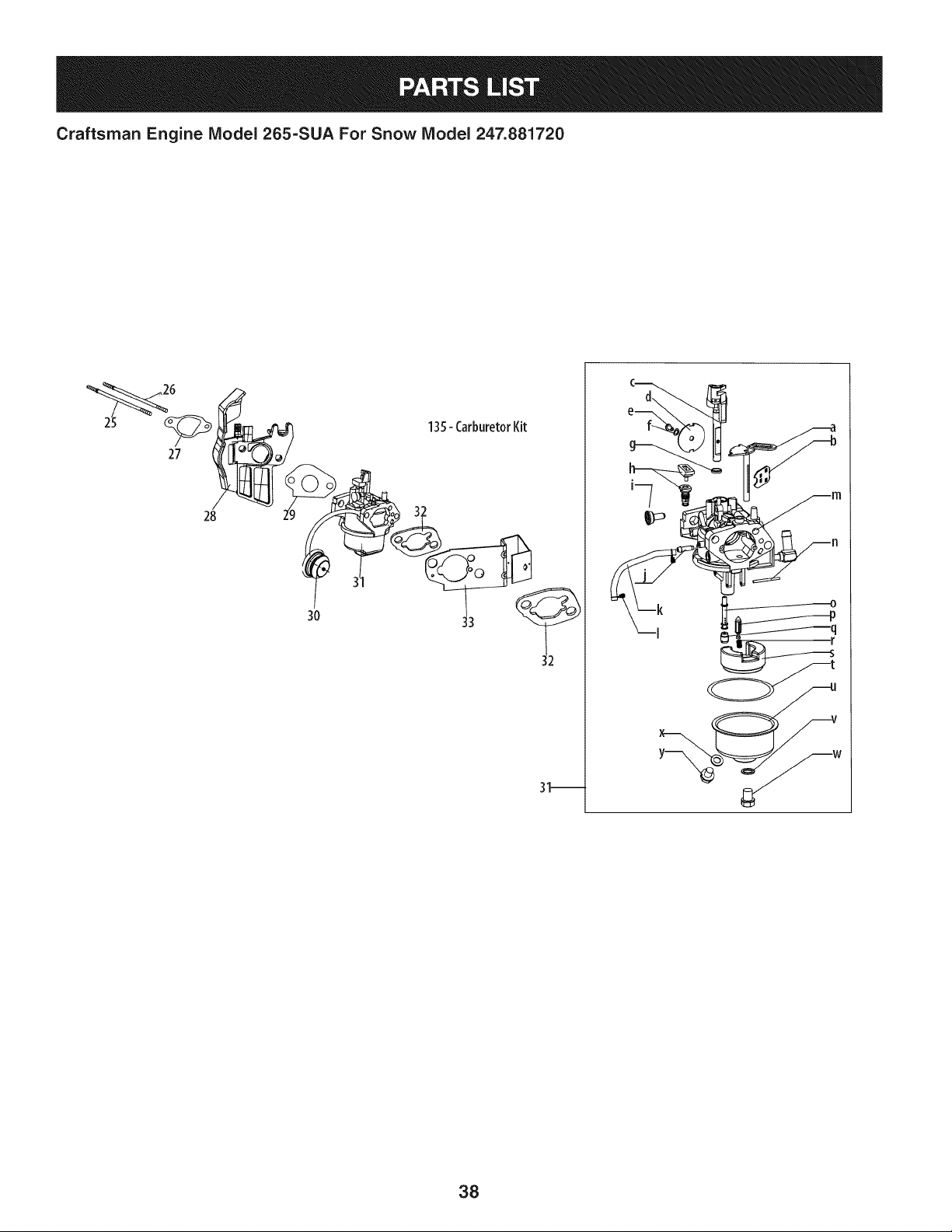
Craftsman Engine IViodel 265=SUA For Snow IViodel 247.881720
27
28
3O
135- CarburetorKit
31_
w
38
Craftsman Engine IViodel 265=SUA For Snow IViodel 247.881720
m
25
26
27
28
29
30
30
31
32
33
135
a
b
C
d
e
f
g
h
I
J
k
I
m
n
o
P
q
r
s
t
U
V
W
X
Y
710-04939
710-04910
951-11567
951-11896
951-11569A
951-10639A
951-11824
951-12705
951-11897
951-11112
951-14050
n/a
n/a
n/a
n/a
710-05469
736-04638
n/a
n/a
n/a
n/a
951-11699
951-11906
n/a
n/a
n/a
951-12875
n/a
n/a
n/a
951-11589
n/a
951-11348
710-04945
951-11349
710-04938
D = O O
Stud M6x117
Stud M6x105
CarburetorInsulatorGasket
CarburetorInsulator
CarburetorGasket
PrimerAssembly
PrimerBulb
CarburetorAssembly
CarburetorGasketPlate
ChokeControl
CarburetorKit
(Incl.h,n,o,p,q,r,s,t,v,x)
ChokeShaft
ChokePlate
ThrottleShaft
ThrottlePlate
ScrewM3x6
LockWasher
Gasket,ThrottlePlate
IdleJet Assembly(0.34)
Idle SpeedAdjustingScrew
PrimerPipe
PrimerHose
HoseClamp
CarburetorBody
FloatPin
EmulsionTube(P18-019)
NeedleValve
MainJet(#73)
NeedleValveSpring
Float
FuelBowlO-Ring
FuelBowl
FuelBowlMountingBoltGasket
FuelBowlMountingBolt
FuelBowlDrain BoltGasket
FuelBowlDrain Bolt
39
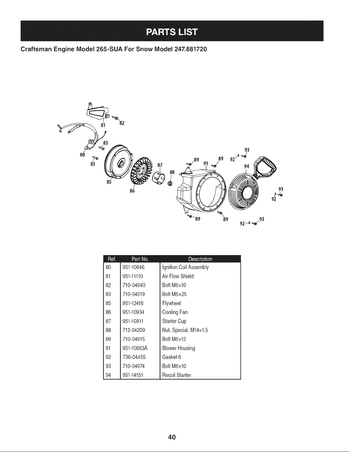
Craftsman Engine Model 265-SUA For Snow Model 247.881720
82
85
86
92/° _3
87 94
93
_89 _89 92-_ _/93
m
8O
81
82
83
85
86
87
88
89
91
92
93
94
951-10646
951-11110
710-04940
710-04919
951-12416
951-10934
951-10911
712-04209
710-04915
951-10663A
736-04455
710-04974
951-14151
D = O O
IgnitionCoil Assembly
Air FlowShield
BoltM6xlO
BoltM6x25
Flywheel
CoolingFan
StarterCup
Nut,Special,M14x1.5
BoltM6x12
BlowerHousing
Gasket6
BoltM6xlO
RecoilStarter
4O
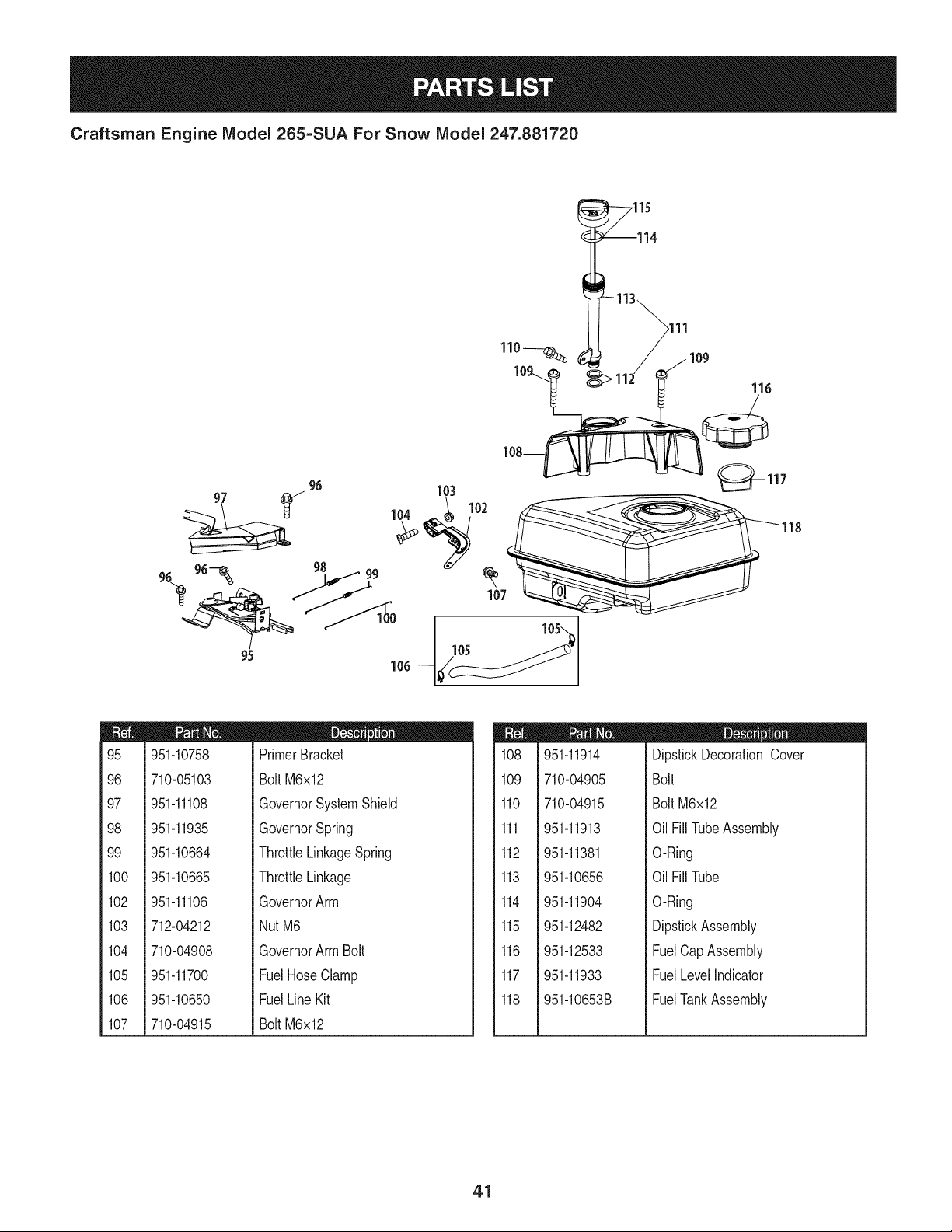
Craftsman Engine Model 265=SUA For Snow Model 247.881720
,115
116
96 103 _--117
9s 99
107
95
m
95
96
97
98
99
1CO
102
103
104
105
106
107
951-10758
710-05103
951-11108
951-11935
951-10664
951-10665
951-11106
712-04212
710-04908
951-11700
951-10650
710-04915
D = O
PrimerBracket
BoltM6x12
GovernorSystemShield
GovernorSpring
ThrottleLinkageSpring
ThrottleLinkage
GovernorArm
NutM6
GovernorArmBolt
FuelHoseClamp
FuelLineKit
BoltM6x12
m
108
109
110
111
112
113
114
115
116
117
118
951-11914
710-04905
710-04915
951-11913
951-11381
951-10656
951-11904
951-12482
951-12533
951-11933
951-10653B
D = O O
DipstickDecorationCover
Bolt
Bolt M6x12
Oil FillTubeAssembly
O-Ring
Oil FillTube
O-Ring
DipstickAssembly
FuelCapAssembly
FuelLevelIndicator
FuelTankAssembly
41
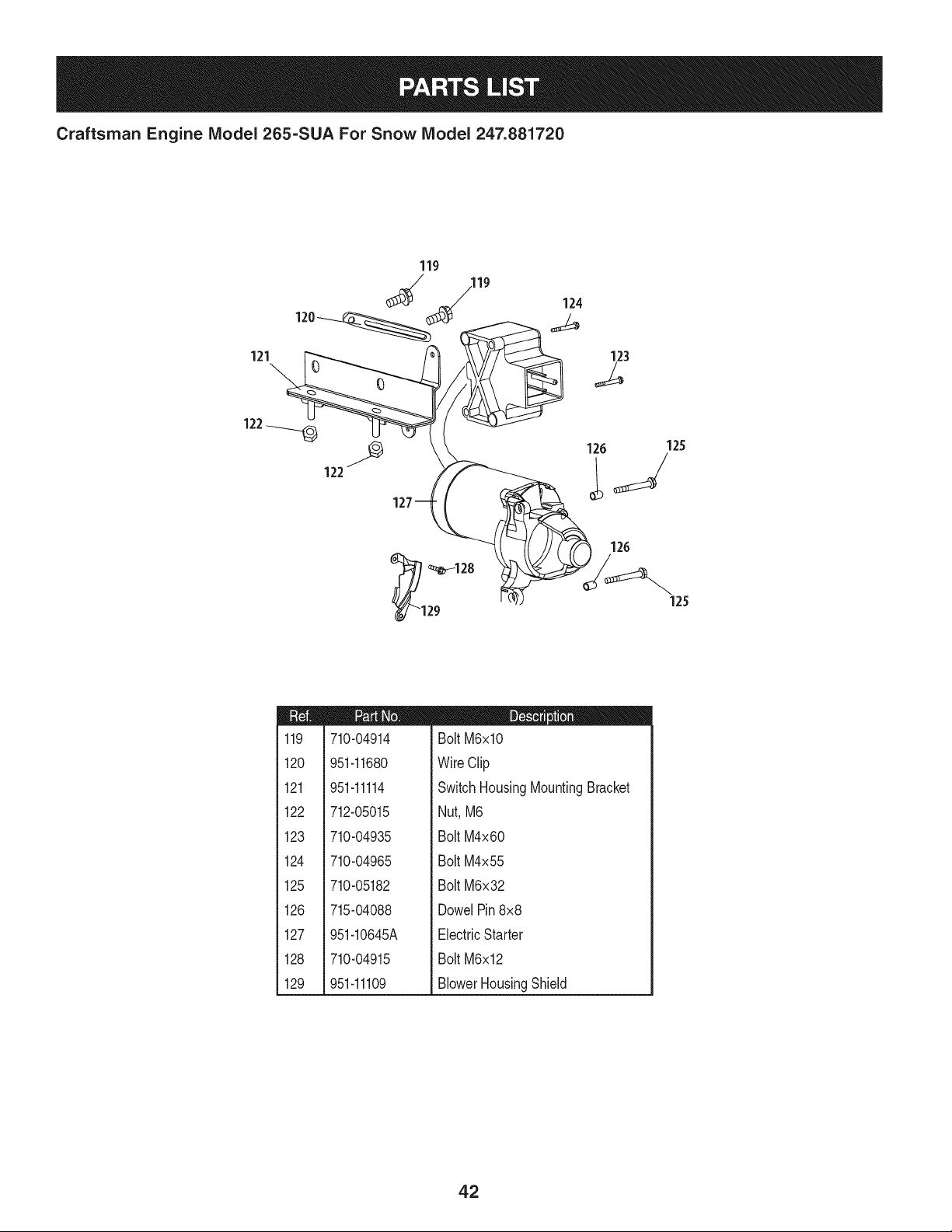
Craftsman Engine Model 265=SUA For Snow Model 247.881720
121
119
120
123
122
126
_i _128
29
126
m
i
1119
1
1
1
i 120
!
i
1121
1
1
1
i 122
1
1
1
i 123
!
i
i 124
1
1
1
i 125
!
!
i
i 126
1
1
i 127
1
1
1
i 128
!
i
1
i 129
1
710-04914
951-11680
951-11114
712-05015
710-04935
710-04965
710-05182
715-04088
951-10645A
710-04915
951-11109
D = O !
BoltM6xlO
WireClip
SwitchHousingMountingBracket
Nut,M6
BoltM4x60
BoltM4x55
BoltM6x32
DowelPin8x8
ElectricStarter
BoltM6x12
BlowerHousingShield
42

Craftsman Snow Thrower IViodel 247.881720
777S32636
1001 InO-NVqlO
7VANV_ 8,HOIVH3dOQV3H"f!
"S33VdHAS13AVH9NO9NIlV_]dO
N3HMNOIIAV3VHIX33Sfl"SH3ONVIS18IV 3OHVHOSIO
1338108]A]N 'S318AFNI$133r80 NMOUHLQIOAV01 "_
"3NIHOVW9NIOIAH3S80 9NIgOOlONA
3UOd38O]dd01S]AVHSlUVdONIAO_3IV 311NAS3]QNVH
ONIH38NIVW3UQNV'3NION3dOIS'SU3A33HOIA3339VgN3810"8
"]IAH3 39UVHOSIQ9013NAO11001/AO'NV310 3SA"g
"133:1QNVSQNVH31VIAdWVNV3U39AV80 Hill]dill HIlM
IOVlNOO"U3OAVONV83113d_JI9NIIVIOUWOHdIVMVd33H"L
777X43688
/ USEE85 ORFUEL
/ CONTAININGMORE ',
THAN 10% ETHANOL
777S32236
777D16343
777D16340
777D18039
777122581
777D18034
43
MTD CONSUMER GROUP INC (MTD), the California Air Resources Board (CARB)
and the United States Environment Protection Agency (U. S. EPA)
Emission Control System Warranty Statement
(Owner's Defect Warranty Rights and Obligations)
EMISSIONCONTROLSYSTEMCOVERAGEIS APPLICABLETOCERTIFIEDENGINESPURCHASEDINCALIFORNIAIN 2005 ANDTHERE-
AFTER,WHICHARE USEDIN CALIFORNIA,ANDTO CERTIFIEDMODELYEAR2005ANDLATERENGINESWHICHARE PURCHASEDAND
USEDELSEWHEREIN THE UNITEDSTATES.
Californiaandelsewherein the UnitedStatesEmissionControlDefectsWarrantyCoverage
The CaliforniaAir ResourcesBoard(CARB),U. S. EPAand MTDare pleasedto explaintheemissionscontrolsystemwarrantyonyour modelyear
2006andlatersmalloff-roadengine.In California,new smalloff-roadenginesmustbe designed,builtand equippedto meettheStatesanti-smog
standards.Elsewhereinthe UnitedStates,newnon-road,spark-ignitionenginescertifiedfor model2005and later,mustmeet similarstandardsset
forthby the U.S. EPA.MTDmustwarrantythe emissioncontrolsystemon yourenginefor the periodof time listed below,providedtherehasbeen
noabuse,neglector impropermaintenanceof your smalloff-roadengine.
Youremissioncontrolsystemmayincludepartssuch as the carburetor,fuel-injectionsystem,the ignitionsystem,and catalyticconverter,fueltanks,
fuel lines,fuel caps,valves,canisters,filters,vaporhoses,clamps,connectors,andotherassociatedemission-relatedcomponents.
Wherea warrantableconditionexists,MTDwill repairyoursmalloff-roadengineat nocost to yourincludingdiagnosis,partsand labor.
MANUFACTURER'S WARRANTY COVERAGE:
Thisemissionscontrolsystemis warrantedfor two years.If anyemission-relatedpart onyourengineis defective,the part will be repairedor
replacedby MTD.
OWNER'S WARRANTY RESPONSIBILITIES:
As the smalloff-roadengineowner,youare responsibleforthe performanceof the requiredmaintenancelisted in your Owner'sManual.MTD
recommendsthatyou retainall yourreceiptscoveringmaintenanceson yoursmalloff-roadengine,but MTDcan not denywarrantysolelyfor the
lackof receiptsor foryour failureto ensurethe performanceto all scheduledmaintenance.
As the smalloff-roadengineowner,youshouldhoweverbeawarethat MTDmaydenyyour warrantycoverageif yoursmalloff-roadengineorpart
hasfaileddue toabuse, neglect,impropermaintenanceor unapprovedmodifications.
Youare responsiblefor presentingyour smalloff-roadengineto an AuthorizedMTDServiceDealeras soonas a problemexists.Thewarranted
repairsshouldbe completedin a reasonableamountof time,notto exceed30 days.
Ifyou haveanyquestionsregardingyourwarrantyrightsand responsibilities,you shouldcontacta MTDServiceRepresentativeat 1-800-800-7310
andaddressis MTDCONSUMERGROUP,RO.Box361131,ClevelandOH,44136-0019.
DEFECTS WARRANTY REQUIREMENTS FOR 1995 AND LATER SMALL OFF-ROAD ENGINES:
Thissectionappliesto 1995and later smalloff-roadengines.The warrantyperiodbeginsonthe datethe engineor equipmentis deliveredto an
ultimatepurchaser.
(a) GeneralEmissionsWarrantyCoverage_
MTDmustwarrantto the ultimatepurchaserand eachsubsequentpurchaserthatthe engineis:
(1)Designed,built,and equippedsoas to conformwithall applicableregulationsadoptedby the Air ResourcesBoardpursuantto its authorityin
Chapters1 and 2,Part 5, Division26of the Healthand SafetyCode;and
(2) Freefromdefectsin materialsandworkmanshipthat causethe failureof a warrantedpart to be identicalin all materialrespectsto the partas
describedin theengine manufacturer'sapplicationfor certificationfora periodof twoyears.
.(b)The warrantyonemissions-relatedpartswill be interpretedas follows:
(1)Anywarrantedpart thatis not scheduledfor replacementas requiredmaintenanceinthe writteninstructionsrequiredby Subsection(c)
mustbewarrantedfor the warrantyperioddefinedin Subsection(a)(2). Ifany such partfails duringthe periodof warrantycoverage,it mustbe
repairedor replacedby MTDaccordingto Subsection(4) below.Anysuch part repairedor replacedunder thewarrantymustbe warrantedfor
the remainingwarrantyperiod.
(2)Any warrantedpartthat is scheduledonlyfor regularinspectioninthe writteninstructionsrequiredby Subsection(c) must be warrantedfor
thewarrantyperioddefinedin Subsection(a)(2).A statementin such writteninstructionsto the effectof "repairor replaceas necessary"will
not reducethe periodof warrantycoverage.Anysuchpart repairedor replacedunderwarrantymustbe warrantedforthe remainingwarranty
period.
(3) Anywarrantedpartthat whichis scheduledfor replacementas requiredmaintenancein the writteninstructionsrequiredby Subsection(c)
mustbewarrantedfor the periodof timepriorto the first scheduledreplacementpointforthat part.Ifthe part failspriorto thefirst scheduled
replacement,the part mustbe repairedor replacedby MTDaccordingto Subsection(4) below.Any suchpart repairedor replacedunder
warrantymustbe warrantedfor the remainderof the periodpriorto the first scheduledreplacementpointfor the part.
(4) Repairor replacementof any warrantedpartunderthewarrantyprovisionsof this article mustbe performedat nochargeto the ownerat a
warrantystation.
(5) Notwithstandingthe provisionsof Subsection(4) above,warrantyservicesor repairsmustbe providedat all MTDdistributioncentersthat
arefranchisedto servicethe subjectengines.
(6)Theownermustnotbechargedfordiagnosticlaborthatleadstothedeterminationthatawarrantedpartisinfactdefective,providedthat
suchdiagnosticworkisperformedatawarrantystation.
(7)Theenginemanufacturerisliablefordamagestootherenginecomponentsproximatelycausedbyafailureunderwarrantyofanywarranted
part.
(8)Throughouttheengine'swarrantyperioddefinedinSubsection(a)(2),MTDwillmaintainasupplyofwarrantedpartssufficienttomeetthe
expecteddemandforsuchparts.
(9)Anyreplacementpartmaybeusedintheperformanceofanywarrantymaintenanceorrepairsandmustbeprovidedwithoutchargetothe
owner.SuchusewillnotreducethewarrantyobligationsofMTD.
(10)Add-onormodifiedpartsthatarenotexemptedbytheAirResourcesBoardmaynotbeused.Theuseofanynon-exemptedadd-onor
modifiedpartsshallbegroundsfordisallowingawarrantyclaimmadeinaccordancewiththisarticle.Theenginemanufacturershallnotbe
liableunderthisarticletowarrantfailuresofwarrantedpartscausedbytheuseofnon-exemptedadd-onormodifiedpart.
(c) MTDwill includea copyof the followingemissionwarrantypartslistwitheach newengine,usingthose portionsof the list applicableto the
e__&gine.
(1)FuelMeteringSystem
• Coldstart enrichmentsystem(soft choke)
,,Carburetorandinternalparts
• Fuel Pump
• FuelTank
(2)Air InductionSystem
• Aircleaner
• Intakemanifold
(3) IgnitionSystem
• Sparkplug(s)
• MagnetoIgnitionSystem
(4)ExhaustSystem
Catalyticconverter
• SAI (Reedvalve)
(5) MiscellaneousItemsUsedin AboveSystem
Vacuum,temperature, position,timesensitivevalvesand switches
Connectorsandassemblies
(6) Evaporativecontrol
• Fuel Hosecertifiedfor ARBevaporativeemissionof 2006.
• Fuel HoseClamps
Tetheredfuel cap
Carboncanister
• Vaporlines
GD0C-100174Rev.B
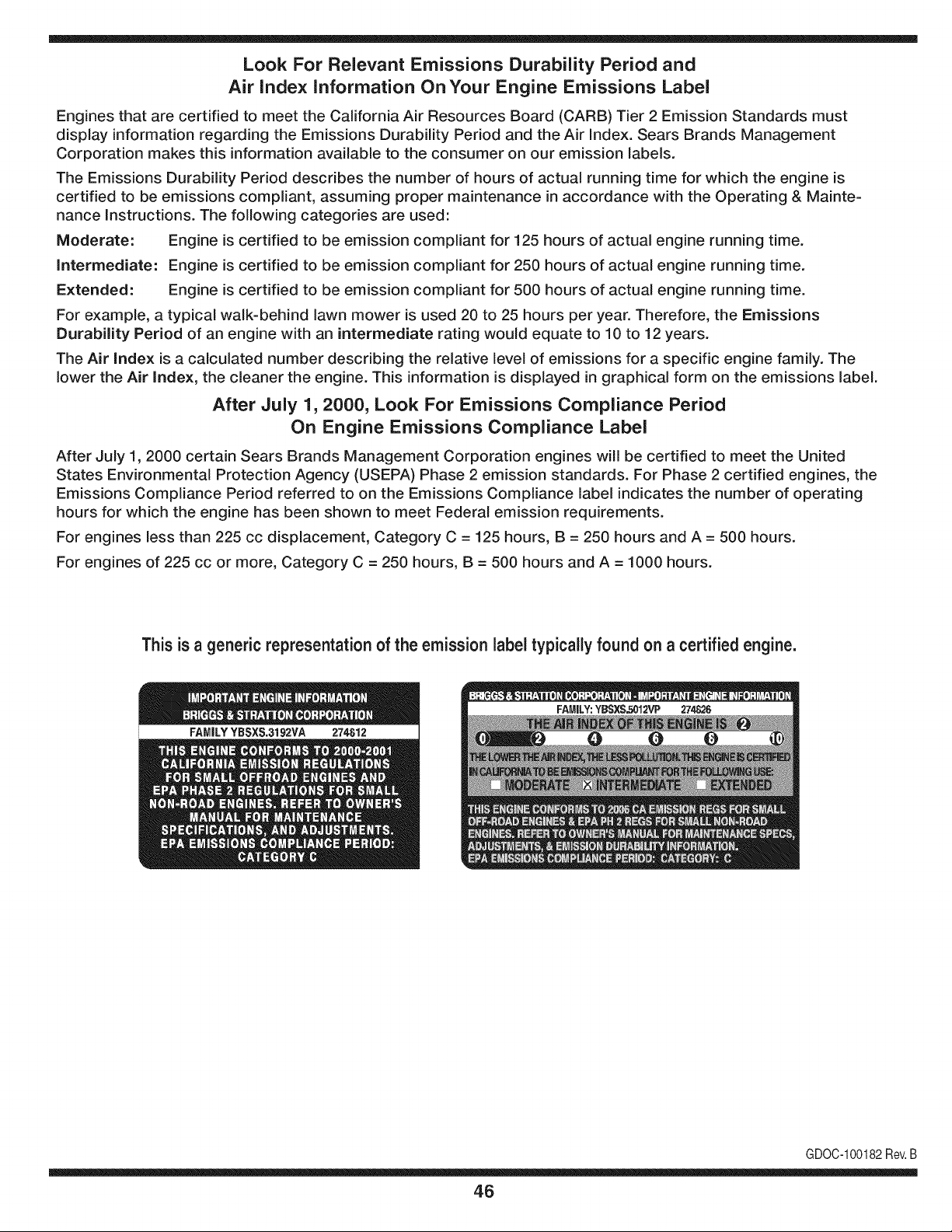
Look For Relevant Emissions Durability Period and
Air index information On Your Engine Emissions Label
Engines that are certified to meet the California Air Resources Board (CARB) Tier 2 Emission Standards must
display information regarding the Emissions Durability Period and the Air Index. Sears Brands Management
Corporation makes this information available to the consumer on our emission labels.
The Emissions Durability Period describes the number of hours of actual running time for which the engine is
certified to be emissions compliant, assuming proper maintenance in accordance with the Operating & Mainte-
nance Instructions. The following categories are used:
Moderate: Engine is certified to be emission compliant for 125 hours of actual engine running time.
Intermediate: Engine is certified to be emission compliant for 250 hours of actual engine running time.
Extended: Engine is certified to be emission compliant for 500 hours of actual engine running time.
For example, a typical walk-behind lawn mower is used 20 to 25 hours per year. Therefore, the Emissions
Durability Period of an engine with an intermediate rating would equate to 10 to 12 years.
The Air index is a calculated number describing the relative level of emissions for a specific engine family. The
lower the Air Index, the cleaner the engine. This information is displayed in graphical form on the emissions label.
After July 1,2000, Look For Emissions Compliance Period
On Engine Emissions Compliance Label
After July 1, 2000 certain Sears Brands Management Corporation engines will be certified to meet the United
States Environmental Protection Agency (USEPA) Phase 2 emission standards. For Phase 2 certified engines, the
Emissions Compliance Period referred to on the Emissions Compliance label indicates the number of operating
hours for which the engine has been shown to meet Federal emission requirements.
For engines less than 225 cc displacement, Category C = 125 hours, B = 250 hours and A = 500 hours.
For engines of 225 cc or more, Category C = 250 hours, B = 500 hours and A = 1000 hours.
This is a generic representation of the emission label typically found on a certified engine.
FAMILYYBSXS.3192VA 274812
GDOC-100182Rev.B
46
Congratulations on making a smart purchase. Your new Craftsman® product is designed and
manufactured for years of dependable operation. But like all products, it may require repair
from time to time. That's when having a Repair Protection Agreement can save you money and
aggravation.
Here's what the Repair Protection Agreement* includes:
[] Expert service by our 10,000 professional repair specialists
[] Unlimited service and no charge for parts and labor on all covered repairs
[] Product replacement up to $1500 if your covered product can't be fixed
[] Discount of 25% from regular price of service and related installed parts not covered by the
agreement; also, 25% off regular price of preventive maintenance check
[] Fast help by phone - we call it Rapid Resolution - phone support from a Sears representative.
Think of us as a "talking owner's manual."
Once you purchase the Repair Protection Agreement, a simple phone call is all that it takes for you
to schedule service. You can call anytime day or night, or schedule a service appointment online.
The Repair Protection Agreement is a risk-free purchase. If you cancel for any reason during the
product warranty period, we will provide a full refund. Or, a prorated refund anytime after the
product warranty period expires. Purchase your Repair Protection Agreement today!
Some limitations and exclusions apply. For prices and additional information in the U.S.A.
call 1=800=827=6655.
*Coverage in Canada varies on some items. For full details call Sears Canada at 1=800=361=
6665.
Sears Installation Service
For Sears professional installation of home appliances, garage door openers, water heaters, and
other major home items, in the U.S.A. or Canada call 1=800=4=MY=HOME®.
47
Declaraci6n de garantia ............................ Pagina 48
Pr,_cticas operaci6n seguras ..................... Pagina 49
Montaje ...................................................... Pagina 53
Operaci6n .................................................. Pagina 57
Servicio y Mantenimiento .......................... Pagina 61
Almacenamiento fuera de temporada ....... Pagina 69
Soluci6n de problemas .............................. Pagina 70
Acuerdo de protecci6n para reparaciones .... Pagina 75
Lista de piezas ........................................... Pagina 26
NOmero de servicio ................................... Cubierta
posterior
GARANTiA COMPLETA CRAFTSMAN POR DOS ANOS
PORDOSANOSapartir dela fechade lacompra,esteproductoest,.garantizadopordefectosen los materialesy la manodeobra.
Los productosdefectuososser_.nreparadossin costoo reemplazadossin costosi la reparaci6nno est,. disponiNe.
Paraobtener informaci6nsobre el alcancede la garantiay solieitar la reparaci6no el reemplazo,visiteel sitio Web:www.craftsman.com
Esta garantia eubre 0NICAMENTElos defectos en los materiales y en la mano de obra. Estagarantia NOcubre:
• Elementosno renovaNesque puedendesgastarsepor eluso normal,duranteel plazodela garanfia,incluyendoentreotros,las barrenas,
las paletasdelas barrenas,los cortadoresde desplazamiento,laszapatasantideslizantes,la placade raspado,lospasadoresdecuchilla,
la bujia,el filtro de air& las correasy el filtrodeaceite.
• Serviciosde mantenimientoest_ndar,cambiosde aceiteo afinaci6n.
• Cambiode neum_ticoso reparadonespor pinchadurascon objetosextemoscomoclavos,espinas,toconeso vidrios.
• Reemplazoo reparaci6nde neum_ficoso ruedascomo resultadodel desgastenormal,un acddente,o funcionamiento
o mantenimientoincorrectos.
• Reparacionesrequeridascomoresultadodel uso inadecuadoporpartedel operador,incluyendoentreotrosel daSoocasionadopor objetos
queimpactanla maquinay que tuercenel bastidor,el ejede la barrena,etc.,o debido a queel motorfueaceleradoenexceso.
• Reparadonesnecesariasdebidoa negligenciadel operador,incluyendoentre otros,daSosmec_nicoy el_ctricoocasionadopor
unalmacenamientonoapropiado,fallaporel uso de aceitede gradoy/o cantidadno apropiadoso falla por nodar mantenimiento
alequipode acuerdocon las instruccionescontenidasenel manualdel operador.
• Limpiezao reparacionesdel motor(sistemade combustible)debidasa combustiblequese determinaestAcontaminadou oxidado(viejo).
Engeneral,el combustibledebeutilizarseen unperbdo no mayorde 30 d[asa partirde su adquisici6n.
• Eldeterioroy desgastenormalde losacabadosexteriores,o reemplazode la etiquetadelproducto.
Lapresentegarantiase anulasi se utilizaesteproductoalgunavezparaprestarservicioscomercialeso si se Ioalquilaa otra persona.
Estagarantialeotorgaderechoslegalesespecificos,peroustedpodria gozarde otros derechosen raz6nde su lugarde residencia.
Sears Brands Management Corporation, Hoffman Estates, IL 60179
Tipode aceitedel motor:
Capacidaddeaceitedel motor:
Capacidaddecombustible:
Bujias:
Separaci6nde lasbujias:
5W-30
20onzas
2 cuartos
F6RTC(951-10292)
.020"a .030"
© Sears Brands,LLC
48
NSrnerode modelo ..........................................................
N_merode serie ..............................................................
Feehade eompra .............................................................
Registrearriba el nOmerodel modelo,el nOmerode seriey la fecha
decompra
Lapresenciadeestesfrnboloindicaquesetratadeinstrucciones
irnportantesdeseguridadquesedebenrespetarparaevitar
ponerenpeligrosuseguridadpersonaly/omaterialyladeotras
personas.Leaysigatodaslasinstruccionesdeestemanualantes
deponerenfuncionarnientoestarn_.quina.Sinorespetaestas
instruccionespodrfaprovocarlesionespersonales.Cuandoveaeste
sfrnbolo,ipresteatenci6nalaadvertencia!
PROPOSICION 65 DE CALIFORNIA
Elescapedel motorde esteproducto,algunosde suscornponentes
y algunoscornponentesdelvehfculocontieneno liberansustancias
qufrnicasque el estado de Californiaconsideraque puedenproducir
c_.ncer,defectosde nacirnientou otros problernasreproductivos.
Estarn_.quinarue construidaparaseroperadade acuerdocon
las reglasde seguridadcontenidaseneste manual.AI igualque
concualquiertipo de equipo rnotorizado,undescuidoo error por
partedeloperadorpuedeproducirlesionesgraves.Esta rn_.quina
es capazde arnputarrnanosy piesy de arrojarobjetoscon gran
fuerza.Deno respetarlas instruccionesde seguridadsiguientesse
puedenproducirlesionesgraveso la rnuerte.
Su responsabilidad--Restrinja el usode esta rn_.quina
rnotorizadaalas personasque lean,cornprendany respetenlas
advertenciase instruccionesqueaparecenen estemanualyen la
rn_.quina.
iGUARDEESTASINSTRUCCIONES!
CAPACITACI6N
• Lea,entienday curnplatodaslas instruccionesincluidasen
la rn_.quinayen los rnanualesantesde rnontarlay utiNzarla.
Guardeestemanualenun lugarseguroparaconsultasfuturasy
peri6dicas,asf cornopara solicitarrepuestos.
• Leael ManualdelOperadory sigatodas las advertenciase
instruccionesde seguridad.Elfracasode hacerasf puedecausar
la heridaseriaal operadory/o personaspresentes.
• Farniliarfcesecontodoslos controlesy con el usoadecuado
delos rnisrnos.Sepa c6rnodetenerlarn_.quinay desactivarlos
controlesr_.pidarnente.
• No perrnitanuncaque los ni_osrnenoresde 14a_osutilicen
estarn_.quina.Los ni_osde 14a_osen adelantedeben leer y
entenderlas instruccionesde operaci6ny norrnasde seguridad
contenidasen este manual,yen la rn_.quinaydebenser entrena-
dosy supervisadosporun adulto.
• Nuncaperrnitaque los adultosoperenestarn_.quinasin recibir
antesla instrucci6napropiada.
• Losobjetosarrojadospor la rn_.quinapuedenproducirlesiones
graves.Planifiqueel patr6nen el queva air arrojandonievepara
evitarque la descargade materialse realicehacialos carninos,
los observadores,etc.
• Mantengaa losobservadores,ayudantes,rnascotasy ni_ospor
Io rnenosa 75piesde la rn_.quinarnientrasla rnisrnaest,.en
funcionarniento.Detengala rn_.quinasi alguienseacerca.
• Seaprecavidoparaevitarpatinarseo caerseespecialrnente
cuandoopera la rn_.quinaen reversa.
PR E PA RATIVO S
Inspeccionerninuciosarnenteel _.readondeutilizar_,el equipo.Saque
todoslos felpudos,peri6dicos,trineos,tablas,cablesy otrosobjetos
extra_oscon los que podrfatropezaro quepodrfanser arrojadospor
labarrena/irnpulsor.
• Paraprotegerselosojos utilice siernpreanteojosoantiparras
de seguridadrnientrasoperala rn_.quinao rnientrasla ajusta
o repara.Losobjetosarrojadosquerebotanpuedenproducir
lesionesocularesgraves.
• Noopere la rn_.quinasin la vestirnentaadecuadaparaestaral
airelibreen invierno.No utilicealhajas,bufandaslargasu otras
prendassueltasquepodrfanenredarseen las partes rn6viles.
UtiNceun calzadoespecialpara superficiesresbaladizas.
• Useun prolongadory untornacorrientede tres cables con
conexi6na tierraparatodas las rn_.quinascon rnotoresde
encendidoel_ctrico.
• Ajustelaalturade la caja del tornacorrienteparaNrnpiarla grava
o las superficiescon piedrastrituradas.
• Desengranetodaslas palancasde controlantesde arrancarel
motor.
• Nuncaintenterealizarajustesrnientrasel motorest,.enrnarcha
exceptoen los casosespecfficarnenterecornendadosen el
manualdel operador.
• Dejeque el motor y la rn_.quinase adaptena laternperatura
exteriorantesde cornenzara sacarla nieve.
49
Manejo seguro de la gasolina
Paraevitarlesionespersonales0 daSosrnaterialestengarnucho
cuidadocuandotrabajecon gasolina.Lagasolinaes surnarnente
inflarnabley sus vaporespuedencausarexplosiones.Si se derrarna
gasolinaencirna0 sobrela ropase puedelesionargravernenteya que
se puedeincendiar. L&vesela piely c&rnbiesede ropade inrnediato.
• Utilices610los recipientesparagasolinaautorizados.
• Apaguetodoslos cigarrillos,cigarros,pipasy otras fuentesde
cornbusfi6n.
• Nuncacarguecombustibleen la rn&quinaen unespaciocerrado.
• Nuncasaquela tapadel combustibleni agreguecombustible
rnientrasel motorest&caliente0 en rnarcha.
• Dejequeel motorse enfriepor I0 rnenosdos rninutosantesde
volvera cargarcombustible.
• Nuncalleneen excesoel dep6sitode combustible.Lleneel
tanquea no rn&sde1/2pulgadapordebajode la basedelcuello
de Ilenadodejandoespacioparala dilataci6ndeIcombustible.
• Vuelvaa colocarla tapade lagasoiinay aj_stelabien.
• Lirnpieel combustibleque se hayaderrarnadosobreel motory el
equipo.Trasladela rn&quinaa otra zona. Espere5 rninutosantes
deencenderel motor.
• Nuncaalrnacenela rn&quina0 el recipientedecombustibleen
unespaciocerradodonde hayafuego,chispas0 luz piloto(por
ejernplo,hornos,calentadoresdeagua,calefactores,secadores
de ropa,etc.).
• Dejequela rn_.quinase enfrieporIo rnenos5 rninutosantesde
guardarla.
• NuncaIlenelos recipientesen el interiordeunvehiculoo carni6n
ocaja de rernolquecon recubrirnientospl_.sticos.Coloque
siernprelos recipientesenel pisoy lejosdel vehiculoantesde
Ilenarlos.
• Sies posible,retireel equipoa gasolinadelcarni6no rernolque
y II_neloen el suelo.Siesto no es posible,Ileneel equipoen un
rernolquecon contenedorport_.til,envez de desdeuna boquilla
dispensadoradegasolina.
• Mantengala boquilladispensadoraen contactocon el hordedel
dep6sitode combustibleo con la aberturadel recipienteentodo
rnornento,hastaterrninarla carga. No utiliceun dispositivode
apertura/cierrede boquilla.
FUNCIONANIIENTO
• No pongalas rnanoso los piescercadelas piezasrotatorias,
en la cajade la barrena/ irnpulsoro en el rnontajedelcanalde
descarga.Hacercontactocon piezasgiratoriaspuederesultaren
laarnputaci6ndernanoso pies.
• La palancadecontrolde la barrena/ irnpulsores un dispositivo
de seguridad.Nuncaevite su funcionarniento.De hacerlola
operaci6nde la rn_.quinaes riesgosay puedeocasionarlesiones.
• Las palancasdecontrol debenfuncionarbien en arnbasdirec-
cionesy regresarautorn_.ticarnentea la posici6nde desengrane
cuandose lassuelta.
• Nuncaoperela rn_.quinasi falta un rnontajedelcanalo si el
rnisrnoest,. daSado.Mantengatodoslosdispositivosde seguri-
daden su lugary en funcionarniento.
• Nuncaenciendaelmotorenespacioscerradoso en una zona
con pocaventilaci6n.Elescapedel motorcontienernon6xidode
carbono,ungas inodoroy letal.
• Noutilice la rn_.quinabajo la influenciadelalcoholo las drogas.
• El silenciadory el motorse calientany puedencausarquernadu-
ras.Nolos toque.Mantengaa los niSosalejados.
• Seasurnarnenteprecavidocuandooperelarn_.quinasobreuna
superficiecon gravao cuandola cruce.Mant_ngasealerta por si
se presentanpeligrosocultoso tr_.nsito.
• Tengacuidadocuandocarnbiede direcci6no cuandoopere
la rn_.quinaenpendientes.Nouse la rn_.quinaen pendientes
pronunciadas.
• Planifiqueel patr6nenel que va air arrojandonieveparaevitar
que la descargade materialse produzcahacialas ventanas,
las paredes,losautorn6viles,etc.y evitarasi posiblesdaSos
rnaterialeso lesionesproducidaspor los rebotes.
• Nuncadirija la descargahacialos niSos,los observadoreso las
rnascotasni deje que nadiese paredelantede la rn_.quina.
• Nosobrecarguela capacidadde la rn_.quinatratandode sacarla
nievernuyr_.pidarnente.
• Nuncaopereesta rn_.quinasin buenavisibilidado ilurninaci6n.
Siernpredebeestar segurode que est,. bien afirrnadoy su-
jetandofirrnernentelas rnanijas.Carnine,nuncacorra.
• Cortela corrientea la barrena/ irnpulsorcuandotransportela
rn_.quinao cuandolarnisrnano est,. en uso.
• Nuncaoperela rn_.quinaa alta velocidadde desplazarniento
sobresuperficiesresbaladizas.Mirehaciaabajoy haciaatr_.sy
tengacuidadocuandovaya rnarchaatr_.s.
• Si la rn_.quinacornenzaraa vibrarde rnaneraanorrnal,detengael
motor,desconecteel cablede la bujia y p6ngalade rnaneraque
hagarnasacontra el motor.Inspeccionela rn_.quinarninuciosa-
rnenteparaver si est,.daSada.Reparetodoslos daSosantesde
encendery operar la rn_.quina.
• Desengranetodas las palancasde controly detengaelmotor
antesdedejar la posici6nde operaci6n(detr_.sde las rnanijas).
Esperea que labarrena/ irnpulsorse detengaporcornpleto
antesdedestaparel rnontajedelcanalo realizarajustese
inspecciones.
• Nuncapongalas rnanosenlas aberturasdedescargao de
recolecci6n.Utilicesiernprela herrarnientade lirnpiezaquese
adjuntaparadestaparla aberturadedescarga.Nodestapeel
rnontajedel canal rnientrasel motorest,.en funcionarniento.
Antesde destaparlo,apagueel motory perrnanezcadetr_.sde las
rnanijashastaque todaslas partesrn6vilesse hayandetenido.
• Uses61ounionesy accesoriosaprobadospot el fabricante(por
ejernplo,pesaspara las ruedas,cadenasparalos neurn_.ticos,
cabinas,etc.). Paraobtenerrn_.sinforrnaci6nacercade estos
ternas,Ilarneal 1-800-469-4663.
5O
• Paraencenderel motor,jale de la cuerdalentarnentehasta que
sientaresistencia,luegojale r_.pidarnente.El replieguer_.pidode
la cuerdade arranque(tensi6nde retroceso)lejalar_,la rnanoy
el brazohaciael motor rn_.sr_.pidodeIo queustedpuedesoltar.
El resultadopuedenserhuesosrotos,fracturas,hernatornaso
esguinces.
• Si se presentansituacionesque no est_.nprevistasen este
manual,seacuidadosoy use el sentidocornOn.
• Parapedirrepuestoso serviciohorarioparaeste producto,Ilarne
a 1-800-469-4663.
MANTENIMIENTO Y ALMACENAMIENTO
• Nuncaalterelos dispositivosde seguridad.Controleperi6dica-
rnenteque funcionencorrectarnente.Rernitasea las secciones
demantenirnientoy ajustede estemanual.
• Antesde realizarla lirnpieza,repararo revisarla rn_.quina,
desengranetodas laspalancasde controly detengael motor.
Esperea quela barrena/ irnpulsorse detengaporcornpleto.
Desconecteel cabledela bujfay p6ngalohaciendornasacontra
el motorpara evitarque se enciendaaccidentalrnente.
• Controlefrecuenternentequetodos lospernosy tornillosest_n
bienajustadosparacornprobarquela rn_.quinase encuentra
encondicionessegurasde funcionarniento.Adern_.s,haga una
inspecci6nvisual de larn_.quinapara verificarsi est,.da_ada.
• No carnbiela configuraci6ndel reguladordel motorni acelere
dernasiadoel rnisrno.El reguladordel motorcontrolala velocidad
rn_.xirnaseguradefuncionarnientodel motor.
• Las placasde raspadoy las zapatasantideslizantesquese
usancon la rn_.quinaquitanievese desgastany se da_an.
Paraprotegersu seguridad,verifiquefrecuenternentetodoslos
cornponentesy reernpl_.celoss61ocon partesde los fabricantes
deequiposoriginales(OEM). iEI usode piezasquenocurnplen
con lasespecificacionesdelequipooriginalpuederesultaren
rendirnientoinadecuadoadern_.sde poneren riesgola seguridad!
• Reviselas palancasde controlperi6dicarnenteparaverificar
queengraneny desengranenadecuadarnentey ajOstelossi es
necesario.Consultela secci6nde ajustesdeeste manualdel
operadorparaobtenerinstrucciones.
• Mantengao reernplacelasetiquetasde seguridade instrucciones
segQnseanecesario.
• Respetelas norrnasreferentesa ladisposici6ncorrectay las
reglarnentacionessobregasolina,aceite,etc. paraprotegerel
medicarnbiente.
• Antesdealrnacenarlarn_.quinaenci_ndalaunosrninutospara
sacarla nieveque hayaquedadoen larnisrnay paraevitarasi
quese congelela barrena/irnpulsor.
• SegOnla Cornisi6nde Seguridadde Productosparael Consurni-
dorde los EstadosUnidos(CPSC)y laAgenciade Protecci6n
Arnbientalde los EstadosUnidos(EPA),esteproductotieneuna
vida Qtilmediade siete (7) a_os, 6 60 horasdefuncionarniento.
AI finalizarla vida Otilmedia,adquieraunarn_.quinanuevao
hagainspeccionaranualrnente_staporun distribuidorde servicio
autorizadoparacerciorarsede que todoslos sisternasrnec_.nicos
y deseguridadfuncionancorrectarnentey notienenexcesivo
desgaste.Si no Iohace,puedenproducirseaccidentes,lesiones
o rnuerte
• Nuncaalrnacenela rn_.quinao el recipientedecombustibleen un
espaciocerradodondehayafuego,chispaso luz pilotocornopor
ejernplo,calentadoresde agua,hornos,secadoresde ropa,etc.
• Consultesiernpreel manualdel operadorparaobtener
instruccionesadecuadaspara el alrnacenarnientofuerade
ternporadaVerifiquefrecuenternentelaIfneade combustible,el
tanque,el tap6n,y losaccesoriosbuscandorajaduraso perdidas.
Reernplacede ser necesario.
• Nod_ arranqueal motorsi no est,. labujiade encendido.
NO MODIFIQUE EL MOTOR
Paraevitarlesionesgraveso la rnuerte,nornodifiqueel motorbajo
ningunacircunstancia.Si carnbiala configuraci6ndel reguladorel
motorpuededescontrolarsey operara velocidadesinseguras.Nunca
carnbielaconfiguraci6nde f_.bricadel reguladordel motor.
AVISO REFERIDO A EMISIONES
Losrnotoresqueest&ncertificadosy curnplencon las regulaciones
de ernisionesfederalesEPAy de CaliforniaparaSORE(Equipos
peque_ostodoterreno)est_.ncertificadosparaoperarcon gasolina
cornOnsinplornoy puedenincluirlossiguientessisternasde control
de ernisiones:Modificaci6ndemotor(EM) y catalizadorde tres vias
(TWO)si est_.nequipadosde esa rnanera.
GUARDACHISPAS
Estarn&quinaest,.equipadacon un motorde cornbusti6ninternay
nodebeser utilizadaen o cercade unterrenoagrestecubiertopor
bosque,rnalezaso hierba exceptosi el sisternade escapedelmotor
est,.equipadocon unarnortiguadorde chispasquecurnplaconlas
leyeslocaleso estatalescorrespondientes,encaso de haberlas.
Sise utilizaun arnortiguadordechispasel operadorIo debe rnantener
en condicionesde usoadecuadas.Enel Estadode Californialas
rnedidasanteriorrnenternencionadassonexigidaspor ley (Arficulo
4442del C6digode RecursosPOblicosde California).Es posible
queexistanleyessirnilaresenotrosestados.Lasleyesfederalesse
aplicanenterritoriosfederales.
Puedeconseguirelarnortiguadorde chispasparael silenciadora
travesde sudistribuidorautorizadode rnotoreso poni_ndoseen
contactocon eldepartarnentode servicios.
51

SiMBOLOS DE SEGURIDAD
Estap_ginadescribelossirnbolosy figurasde seguridadinternacionalesquepuedenapareceren este producto.Leael manualdeloperador
)araobtenerla inforrnaci6nterrninadasobreseguridad,reunirse,operaci6ny rnantenimientoy reparaci6n.
i
i
LEAELMANUAL DELOPERADOR(S)
Lea,entienda, y siga todas lasinstrucciones en el manual (es)antes de intentar reunirse y funcionar.
LA ADVERTENCIA -- PLATOS ROTATORIOS
Guarde manos de entrada y aperturas de la descarga mientras la m_iquina corre. Alli ellos hacen para
girar platos dentro.
LA ADVERTENCIA- LAMINAS ROTATIVAS
Guarde manos de entrada y aperturas de descarga mientras la m_iquina corre. Alli hacen girar I_iminas
dentro.
LA ADVERTENCIA -- TALADRO ROTATIVO
No ponga manos o pies cerca del giro de partes, en el alojamiento de taladro/aspa o asamblea de
tolva. Contacto con las partes rotativas puede amputar manos y pies.
OBJETOS LANZADOS POR ADVERTENClA
Esta m_iquina puede recoger y lanzar objetos que pueden causar la herida personal seria.
GASOLINA DE ADVERTENClA ESINFLAMABLE
Permita que el motor se enfrie al menos dos minutos antes del reabastecimiento de combustible.
ADVERTENCIA -- MONOXIDO DE CARBONO
Nunca dirijas un motor dentro o en un _irea mal ventilada. Los gases de combusti6n de motor
contienen el mon6xido de carbono, un gas inodoro y mortal.
ADVERTENCIA -- ELECTROCHOQUE
No use eljuez de salida el6ctrico del motor en la Iluvia.
52
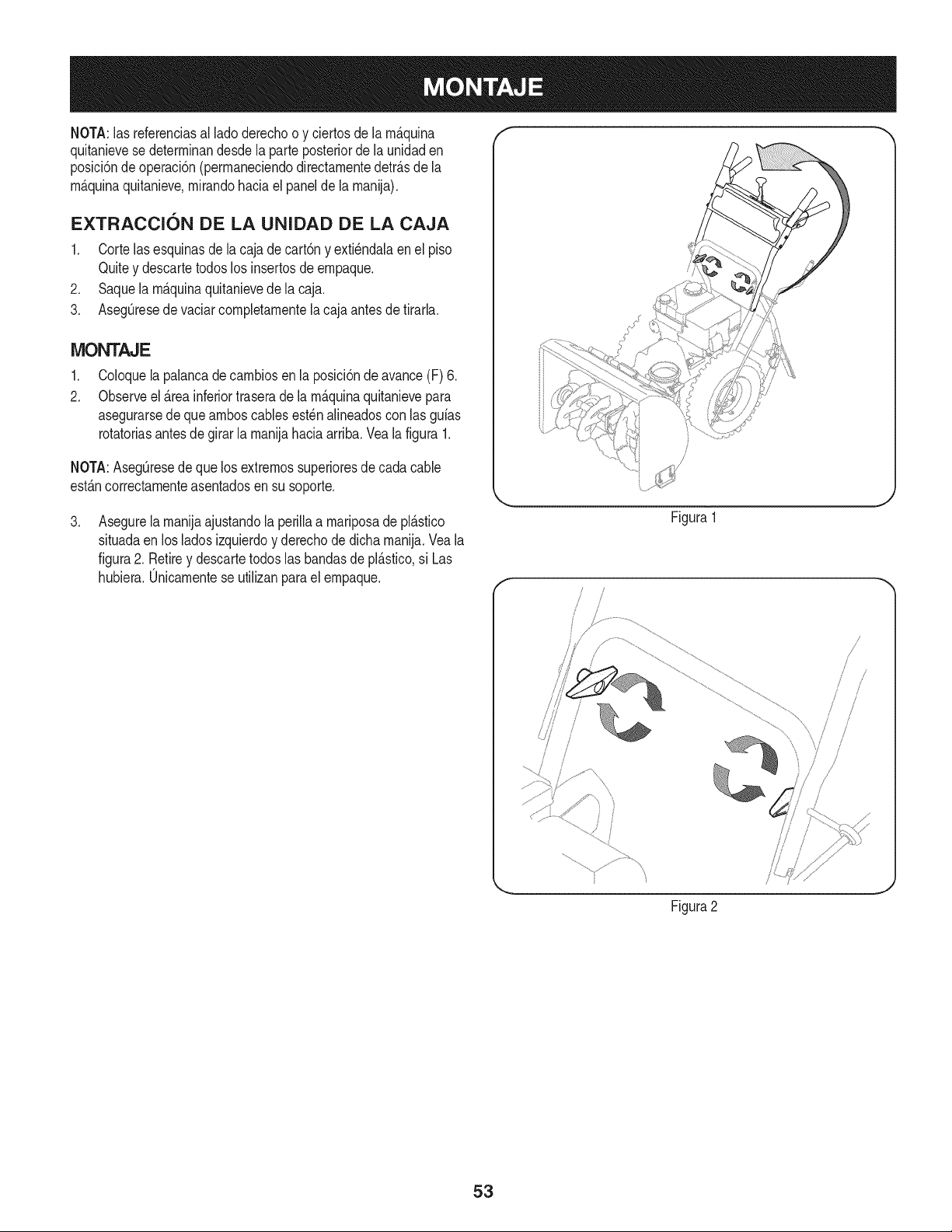
NOTA:las referenciasal ladoderechoo y ciertosde la m_.quina
quitanievese determinandesdela parteposteriorde la unJdaden
posicJ6nde operacJ6n(permaneciendodirectamentedetr_.sde la
m_.quinaquitanJeve,mirandohaciael panelde la manija),
EXTRACCION DE LA UNIDAD DE LA CAJA
1. Cortelasesquinasdela cajade cart6ny exti6ndalaenel piso
Quitey descartetodoslos insertosde empaque.
2. Saquela m_.quinaquitanievede la caja.
3. Aseg0resede vaciarcompletamentela cajaantesde tirarla.
iVIONTAJE
,
2.
Coloquela palancade cambiosen la posici6ndeavance(F) 6.
Observeel _.reainferiortraserade la m_.quinaquitanievepara
asegurarsede que amboscablesest6nalineadoscon las gufas
rotatorJasantesdegirarla manijahacia arrJba,Veala figura 1,
NOTA:Aseg0resede quelos extremossuperioresdecada cable
estAncorrectamenteasentadosensu soporte.
,
Asegurela manijaajustandola perillaa mariposade plAstico
situadaen losladosizquierdoy derechode dichamanija.Vea la
figura2. Retirey descartetodos lasbandasdeplAstico,si Las
hubiera.0nicamentese utilizanparael empaque.
f
Figura1
J
/ /
/ /
/
/
Figura2
J
53
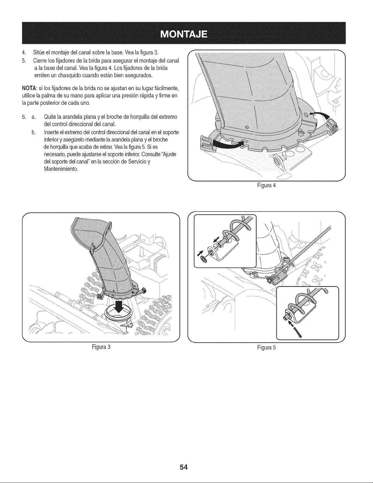
4. f i_
5. i
SitOeel montajedel canalsobrela base.Vealafigura3.
Cierrelosfijadoresde la brida para asegurarelmontajedel canal
a la basedelcanal.Veala figura4. Losfijadoresde labrida
emitenunchasquidocuandoest_.nbienasegurados.
NOTA:si losfijadoresde la brida no seajustanen su lugarf_.clmente,
utilicelapalmadesu rnanoparaaplcar una presi6nr_.piday firme en
la parteposteriorde cadauno.
.
a.
b.
Quitelaarandelaplanay el brochede horquiladel extremo
delcontroldireccionaldel canal.
Inserteel extremodelcontroldireccionaldelcanalenel soporte
inferiory asegOrelomediantelaarandelaplanay el broche
dehorquilaqueacabade retirar.Vealafigura5.Sies
necesario,puedeajustarseelsoporteinferior.Consute"Ajuste
delsoportedelcanal"enla secci6nde Servicioy
Mantenimiento.
Figura4
F -,, f
J
Figura3
Figura5
\
54
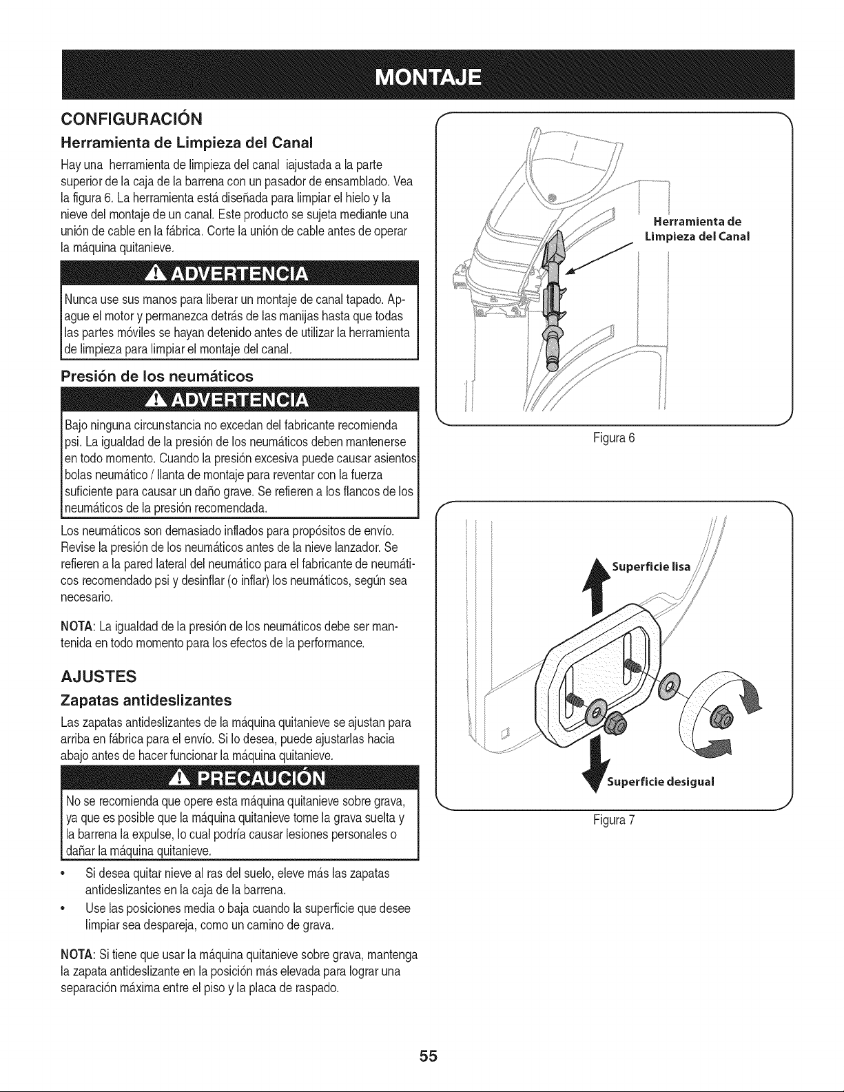
CONFIGURACION
Herramienta de Lirnpieza del Canal
Hayuna herrarnientade lirnpiezadel canal iajustadaa laparte
superiorde lacaja dela barrenacon un pasadorde ensarnNado.Vea
la figura6. LaherrarnientaestAdiseSadaparalirnpiarel hieloy la
nievedelrnontajede uncanal.Esteproductose sujetarnedianteuna
unbn de cableen la f_.brica.Corte la unbn de cableantesde operar
la rnAquinaquitanieve.
Nuncausesusrnanosparaliberarun rnontajede canaltapado.Ap-
agueel motory perrnanezcadetr_.sde las rnanijashastaquetodas
laspartesrn6vilesse hayandetenidoantesde utilizarla herrarnienta
de lirnpiezaparalirnpiarel rnontajedelcanal.
Presi6n de los neumaticos
Bajoningunacircunstanciano excedandel fabricanterecornienda
psi.Laigualdadde la presi6nde los neurn_.ticosdebenrnantenerse
entodo rnornento.Cuandolapresi6nexcesivapuedecausarasientos
bolasneurn_.tico/ Ilantadernontajeparareventarcon la fuerza
suficienteparacausarun da_o grave.Se refierena los fiancosde los
neurn_.ticosde la presi6nrecornendada.
Los neurn_.ticosson dernasiadoinfladosparaprop6sitosde envio.
Revisela presi6nde los neurn_.ticosantesde la nievelanzador.Se
refierena la paredlateraldel neurn_.ticoparael fabricantede neurn_.ti-
cos recornendadopsi y desinfiar(o infiar)losneurn_.ticos,segQnsea
necesario.
NOTA:Laigualdaddela presi6nde los neurn_.ticosdebeset man-
tenidaentodo rnornentopara los efectosde la performance.
AJUSTES
Zapatas antideslizantes
Las zapatasantideslizantesdela rn_.quinaquitanieveseajustanpara
arribaen f_.bricaparaelenvio.Si Iodesea,puedeajustarlashacia
abajoantesde hacerfuncionarla rn_.quinaquitanieve.
Nose recorniendaque opereesta rn_.quinaquitanievesobregrava,
yaquees posiblequela rn_.quinaquitanievetomela gravasuelta y
labarrenala expulse,Iocual podriacausarlesionespersonaleso
da_arla rn_.quinaquitanieve.
• Si deseaquitarnieveal rasdel suelo,elevern_.slaszapatas
antideslizantesen la cajade la barrena.
• Use las posicionesmediao baja cuandola superficiequedesee
lirnpiarseadespareja,cornouncarninode grava.
Herramienta de
Lira )ieza del Canal
Figura6
Superficie lisa
Superficie desigual
Figura7
NOTA:Sitieneque usarla rn_.quinaquitanievesobregrava,rnantenga
la zapataantideslizanteen la posici6nrn_.selevadaparaIograruna
separaci6nrn_.xirnaentreel pisoy la placade raspado.
55
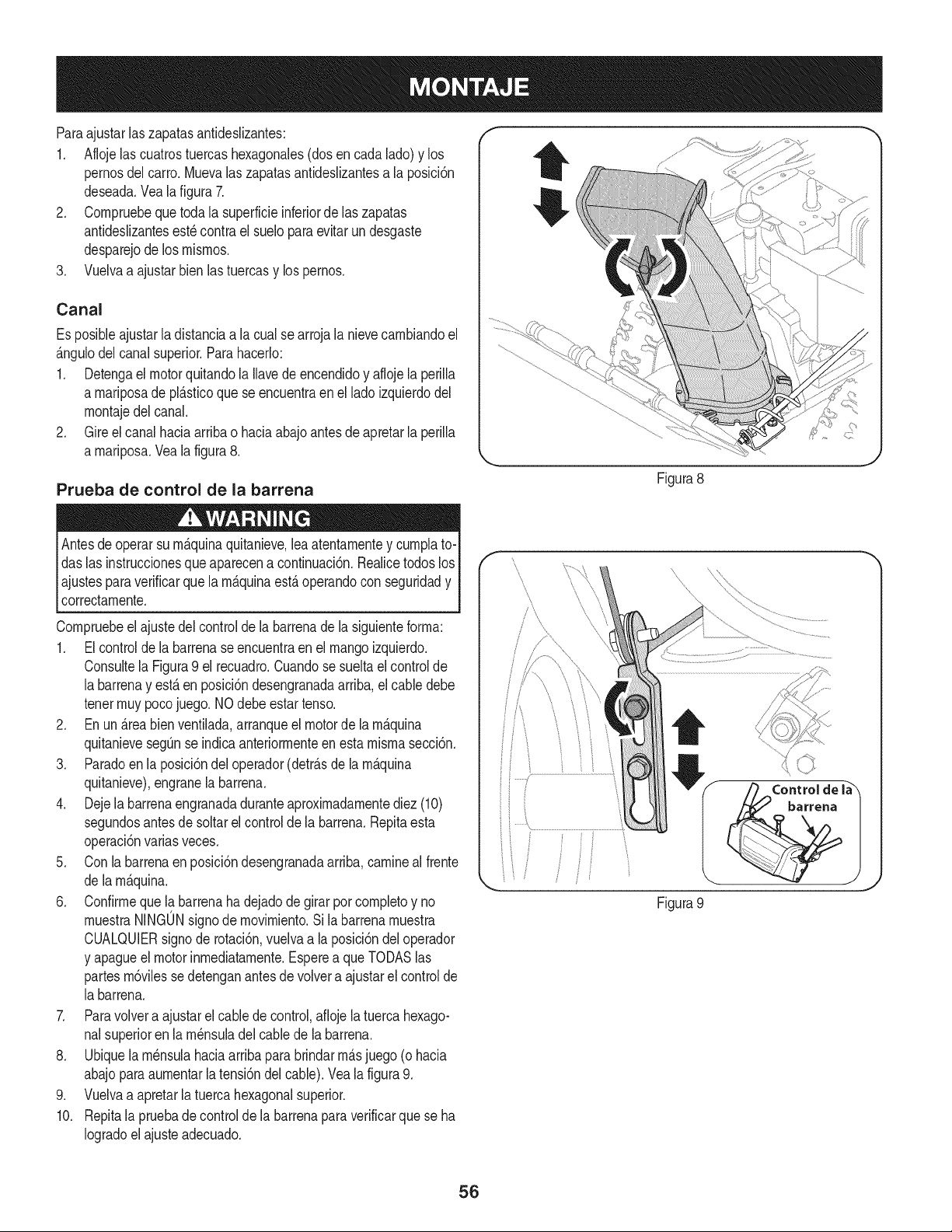
Paraajustarlaszapatasantideslizantes:
1. Aflojelas cuatrostuercashexagonales(dosencada lado)y los
pernosdel carro.Muevalas zapatasantideslizantesa la posici6n
deseada.Veala figura7.
2. Cornpruebequetoda la superficieinferiorde laszapatas
antideslizantesest_contra el sueloparaevitarun desgaste
desparejode los rnisrnos.
3. Vuelvaa ajustarbien lastuercasy lospernos.
Canal
Es posibleajustarla distanciaa la cualse arroja la nievecarnbiandoel
_.ngulodel canal superior.Parahacerlo:
1. Detengael motorquitandola Ilavedeencendidoy aflojela perilla
a rnariposade pl_.sticoque se encuentraenel ladoizquierdodel
rnontajedel canal.
2. Gire el canalhacia arribao haciaabajoantesdeapretarlaperilla
a rnariposa.Vea la figura8.
Prueba de control de la barrena
operarsu rn&quinaquitanieve,lea atentarnentey curnplato-I
Antesde
das las instruccionesque aparecena continuaci6n.RealicetodoslosI
ajustesparaverificarque larn_.quinaest,. operandocon seguridady I
correctarnente, j
Cornpruebeel ajustedel controlde labarrenadela siguienteforrna:
1. El controlde la barrenaseencuentraen el mangoizquierdo.
Consultela Figura9 el recuadro.Cuandose sueltael controlde
la barrenay est,.en posici6ndesengranadaarriba,el cable debe
tenerrnuypocojuego.NOdebeestartenso.
2. En un _.reabien ventilada,arranqueel motorde larn_.quina
quitanievesegQnse indicaanteriorrnenteen estarnisrnasecci6n.
3. Paradoen la posici6ndel operador(detr_.sde la rn_.quina
quitanieve),engranela barrena.
4. Dejela barrenaengranadaduranteaproxirnadarnentediez (10)
segundosantesde soltarel controlde la barrena.Repitaesta
operaci6nvarias veces.
5. Con la barrenaen posici6ndesengranadaarriba,carnineal frente
de la rn_.quina.
6. Confirrneque la barrenaha dejado de girar porcornpletoy no
rnuestraNINGONsignodernovirniento.Si la barrenarnuestra
CUALQUIERsignode rotaci6n,vuelvaa la posici6ndel operador
y apagueel motorinrnediatarnente.Esperea queTODASlas
partesrn6vilessedetenganantesde volvera ajustarel controlde
la barrena.
7. Paravolvera ajustarel cablede control,aflojela tuercahexago-
nalsuperioren la rn_nsuladelcablede la barrena.
8. Ubiquela rn_nsulahaciaarribaparabrindarrn_.sjuego (o hacia
abajoparaaurnentarla tensi6ndelcable).Vea la figura9.
9. Vuelvaa apretarla tuercahexagonalsuperior.
10. Repitala pruebadecontrolde la barrenapara verificarquese ha
Iogradoel ajuste adecuado.
Figura8
Figura 9
56
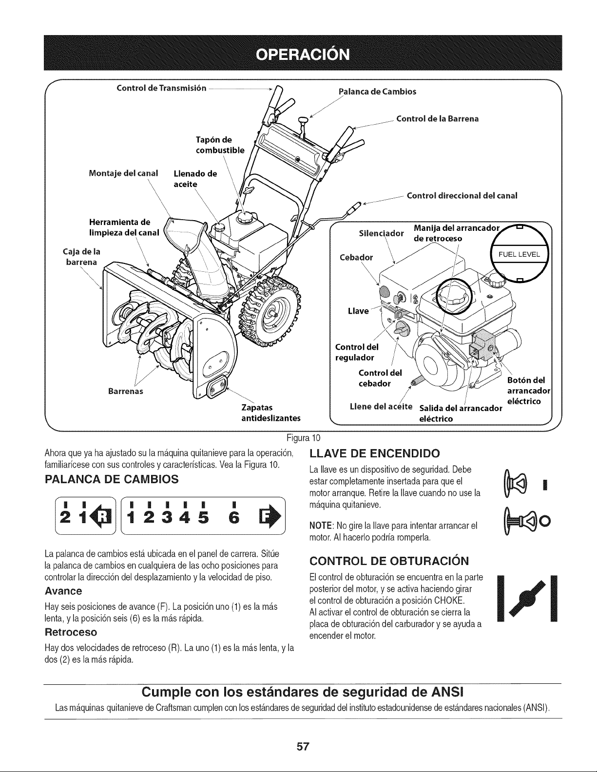
Control de Transmisi6n
Palanca de Cambios
J
.._Controlde la Barrena
Tap6n de
combustible
\
Montajedel canal
\\\
Herramienta de
limpieza del canal
\
\
Caja de la \
barrena
\
\,
Llenado de
aceite
\\
\
Barrenas
Zapatas
antideslizantes
Figura10
Ahoraqueya ha ajustadosu la rn_.quinaquitanieveparalaoperaci6n,
farniliaricesecon sus controlesy caracteristicas.Veala Figura10.
PALANCA DE CAMBIOS
21 12345 6
Lapalancade carnbiosest,.ubicadaenel paneldecarrera.SitQe
lapalancade carnbiosencualquierade lasocho posicionespara
controlarladirecci6ndeldesplazarnientoy la velocidadde piso.
Avance
Hayseisposicionesde avance(F). Laposici6nuno (1) es la rn_.s
lenta,y la posici6nseis (6) es la rn_.sr_.pida.
Retroceso
Haydos velocidadesde retroceso(R). Launo(1)es larn_.slenta,y la
dos (2) es la rn_.sr_.pida.
Control direccional del canal
f . . Manija del arrancador
Sdenc_aclor de retroceso
Cebador __
Llave
Control del
regulador
Control del
cebador
/
Llene del acelte Salida del a rancador
\
Bot6n del
arrancador
el_ctrico
J
J
LLAVE DE ENCENDIDO
La Ilavees un dispositivode seguridad.Debe
estarcornpletarnenteinsertadaparaque el
motorarranque.Retirela Ilavecuandono usela
rn_.quinaquitanieve.
NOTE:Nogire la Ilavepara intentararrancarel
motor.AI hacerlopodriarornperla.
CONTROL DE OBTURACION
Elcontrolde obturaci6nse encuentraen laparte
posteriordel motor,y se activahaciendogirar
elcontroldeobturaci6na posici6nCHOKE.
AIactivarel controlde obturaci6nse cierrala
placadeobturaci6ndel carburadory seayudaa
encenderel motor.
Cumple con los estandares de seguridad de ANSi
LasrnAquinasquitanievedeCraftsmancurnplenconlosestAndaresde seguridaddelinstitutoestadounidensede est&ndaresnacionales(ANSI).
57
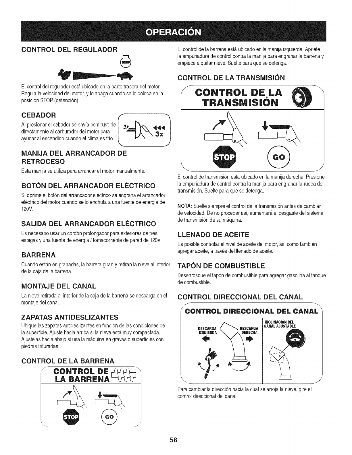
CONTROL DEL REGULADOR
Elcontrol del regulador estfi ubicado en la parte trasera del motor.
Negula la velocidad del motor, y Io apaga cuando se Iocoloca en la
posicidn STOP (detencidn).
CEBADOR
AI presionarel cebadorse enviacombustible
directamenteal carburadordelmotorpara
ayudaral encendidocuandoel climaes frio.
MANIJA DEL ARRANCADOR DE
RETROCESO
Estamanijase utiliza paraarrancarel motor manualmente.
BOTON DEL ARRANCADOR ELECTRICO
Sioprimeel bot6ndel arrancadorel_ctricose engranael arrancador
el_ctricodel motorcuandose1oenchufaa unafuentedeenergiade
120V.
SALIDA DEL ARRANCADOR ELI_CTRICO
Es necesariousarun cord6nprolongadorparaexterioresdetres
espigasy unafuentede energia/ tomacorrientede paredde 120V.
BARRENA
Cuandoest_.nen granadas,(a barreragirany retiran(anieveal interior
dela cajade la barrena.
MONTAJE DEL CANAL
Lanieve retiradaal interiorde la cajade labarrenase descargaen el
montajedel canal.
ZAPATAS ANTIDESLIZANTES
Ubiquelaszapatasantidesiizantesen funci6ndelascondicionesde
(asuperficie.Ajustehaciaarribasi la nieveest,.muy compactada.
AjQstelashaciaabajosi usala m_.quinaengravaso superficiescon
piedrastrituradas.
CONTROL DE LA BARRENA
/ CONTROL DE _---1 \
LA BARRENA
@
J
Elcontrolde (abarrenaest,. ubicadoen (amanijaizquierda.Apriete
la empu_aduradecontrolcontra la manijapara engranarla barrenay
empiecea quitarnieve.Suelteparaque se detenga.
CONTROL DE LA TRANSMISION
/s CONTROL DE LA
TRANSIVi|S|()N
Elcontroldetransmisi6nest,. ubicadoen la manijaderecha.Presione
la empu_aduradecontrolcontra la manijapara engranarla ruedade
transmisi6n.Sueltepara que sedetenga.
NOTA:Sueltesiempreel controlde latransmisi6nantesde cambiar
de velocidad.Deno procederasi,aumentar_,el desgastedel sistema
de transmisi6nde su m_.quina.
LLENADO DE ACEITE
Esposiblecontrolarel nivelde aceite del motor,asi comotambi_n
agregaraceite,atravesdel((enadodeaceite.
TAPON DE COMBUSTIBLE
Desenrosqueel tap6nde combustibleparaagregargasolinaal tanque
de combustible.
CONTROL DIRECCIONAL DEL CANAL
JCONTROL DiRECCiONAL DEL CANAL
DESCARGA
IZQUIERDA
DESCABGA
INCLINACI6N DEL
CANALAJUSTABLE
__ %%=
#
Paracambiarladirecci6nhacia(acualse arroja(anieve,gireel
controldireccionaldelcanal.
58
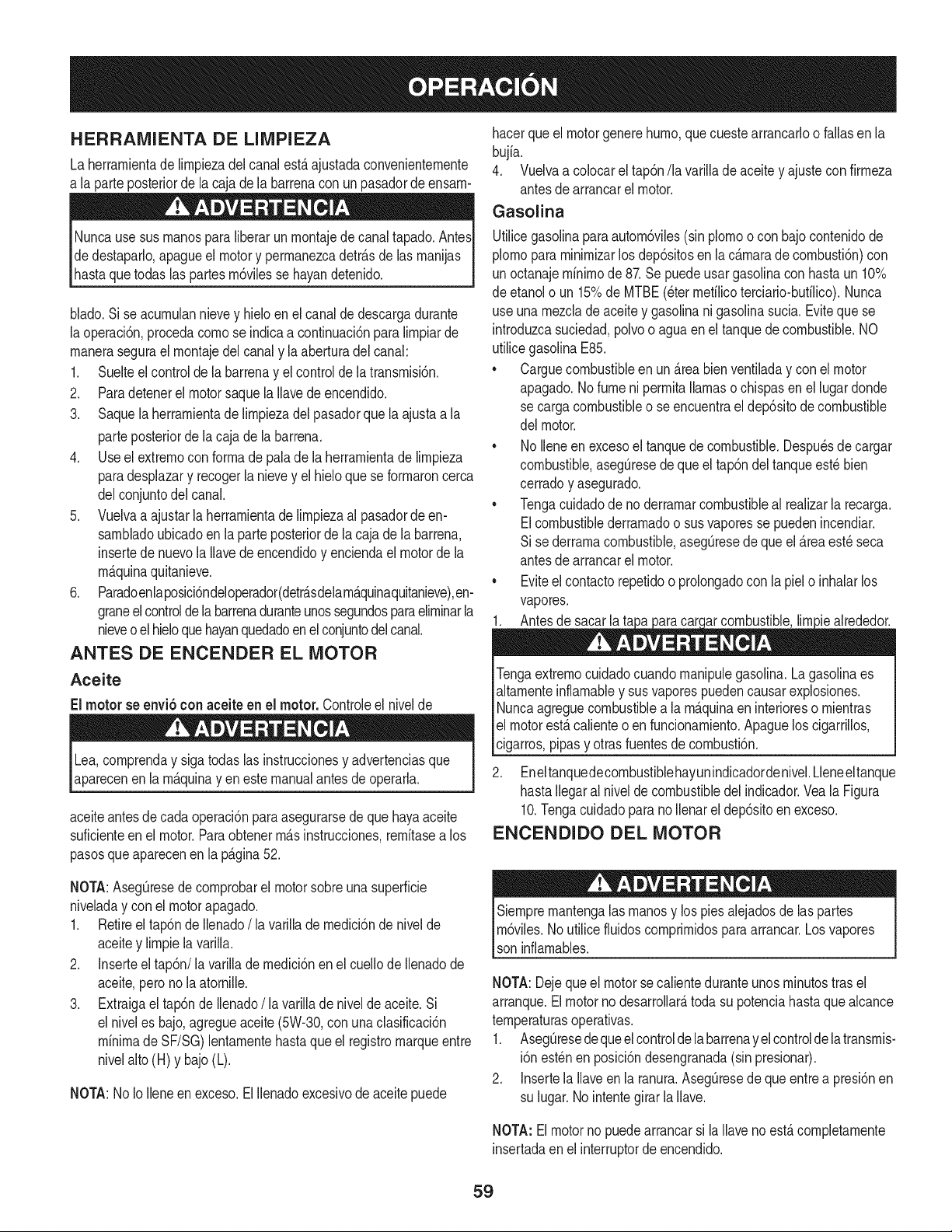
HERRAIVllENTA DE LINIPIEZA
Laherrarnientade lirnpiezadel canalesta ajustadaconvenienternente
a la parte posteriorde lacaja dela barrenacon un pasadordeensarn-
Nuncause susrnanosparaliberarunrnontajede canaltapado.AntesI
de destaparlo,apagueel motory perrnanezcadetr_sde las rnanijas
hastaquetodas as partesrn6v es se hayandetendo. I
blado.Sise acurnulannievey hielo en el canalde descargadurante
laoperaci6n,procedacornose indicaa continuaci6nparalirnpiarde
rnanerasegurael rnontajedel canaly la aberturadel canal:
1. Suelteel controlde labarrenay el controlde la transrnisi6n.
2. Paradetenerel motorsaquela Ilavedeencendido.
3. Saquela herrarnientade lirnpiezadel pasadorque la ajustaa la
parteposteriorde la caja de labarrena.
4. Useel extrernocon forrnade paladela herrarnientade lirnpieza
paradesplazary recogerlanievey el hielo que se forrnaroncerca
delconjuntodel canal.
5. Vuelvaa ajustarla herrarnientade lirnpiezaal pasadordeen-
sarnbladoubicadoen la parteposteriorde la caja de labarrena,
insertede nuevola Ilavedeencendidoy enciendael motorde la
rn_.quinaquitanieve.
6. Paradoenlaposici6ndeloperador(detrAsdelarn_quinaquitanieve),en-
graneelcontroldelabarrenaduranteunossegundosparaelirninarla
nieveo elhieloquehayanquedadoenel conjuntodelcanal.
ANTES DE ENCENDER EL MOTOR
Aceite
El motor se envi6con aceite en el motor.Controleel nivelde
Lea,cornprenday sigatodas las instruccionesy advertenciasque
aparecenen la rn_quinay en estemanualantes de operarla.
aceiteantesde cadaoperaci6nparaasegurarsede quehayaaceite
suficienteenel motor.Paraobtenerrn_sinstrucciones,rernitasea los
pasosqueaparecenenla p_gina52.
hacerqueel motorgenerehurno,quecuestearrancarloo fallas en la
bujia.
4. Vuelvaa colocarel tap6n/la varillade aceite y ajustecon firrneza
antesde arrancarel motor.
Gasolina
Utilicegasolinaparaautorn6viles(sin plornoocon bajocontenidode
plornopararninirnizarlos dep6sitosen lac_rnarade cornbusti6n)con
un octanajerninirnode 87.Sepuedeusar gasolinacon hastaun 10%
de etanolo un 15%de MTBE(eterrnefilicoterciario-bufilico).Nunca
use unarnezclade aceitey gasolinani gasolinasucia. Evitequese
introduzcasuciedad,polvoo aguaen el tanquedecombustible.NO
utilicegasolinaE85.
• Carguecombustibleen un_reabienventiladay con el motor
apagado.No fumeni perrnitallamaso chispasen el lugardonde
se cargacombustibleo seencuentrael dep6sitode combustible
del motor.
• NoIleneen excesoel tanquede combustible.Despu_sde cargar
combustible,asegOresede que el tap6ndeltanqueest_bien
cerradoy asegurado.
• Tengacuidadode no derrarnarcombustibleal realizarla recarga.
Elcombustiblederrarnadoo susvaporesse puedenincendiar.
Si se derrarnacombustible,asegOresede que el _reaest_seca
antesde arrancarel motor.
• Eviteel contactorepetidoo prolongadocon lapielo inhalarlos
vapores.
1. Antesde sacar la ta ar combustible,lirn_iealrededor.
Tengaextrernocuidadocuandornanipulegasolina.Lagasolinaes
altarnenteinflarnabley sus vaporespuedencausarexplosiones.
Nuncaagreguecombustiblea la rn_.quinaen interioreso rnientras
lel motorest,.calienteo en funcionarniento.Apaguelos cigarrillos,
[cigarros,pipasy otrasfuentesde cornbusti6n.
2. Eneltanquedecornbustiblehayunindicadordenivel.Lleneeltanque
hastaIlegaral nivelde combustibledel indicador.Veala Figura
10.Tengacuidadoparano Ilenarel dep6sitoen exceso.
ENCENDIDO DEL MOTOR
NOTA:AsegQresede cornprobarel motorsobreuna superficie
niveladay con el motor apagado.
1. Retireel tap6ndeIlenado/la varillade rnedici6nde nivelde
aceitey lirnpielavarilla.
2. Inserteel tap6n/la varillade rnedici6nen el cuellode Ilenadode
aceite,pero no laatornille.
3. Extraigael tap6nde Ilenado/ la varillade nivelde aceite.Si
el niveles bajo,agregueaceite(5W-30,con unaclasificaci6n
minimadeSF/SG)lentarnentehastaqueel registromarqueentre
nivelalto(H) y bajo(L).
NOTA:NoIo Ileneenexceso.ElIlenadoexcesivode aceitepuede
Siernprernantengalas rnanosy lospies alejadosde las partes
rn6viles.Noutilice fluidoscornprirnidosparaarrancar.Los vapores
son infiarnables.
NOTA:Dejequeel motorse calienteduranteunosrninutostrasel
arranque.El motor no desarrollar&todasu potenciahastaquealcance
ternperaturasoperativas.
1. AsegQresedequeelcontrolde la barrenay el controlde la transrnis-
i6n est_nen posici6ndesengranada(sinpresionar).
2. Insertela Ilaveen la ranura.AsegQresede queentrea presi6nen
su lugar.No intentegirar la Ilave.
NOTA: Elmotorno puedearrancarsi laIlaveno est,. cornpletarnente
insertadaenel interruptordeencendido.
59
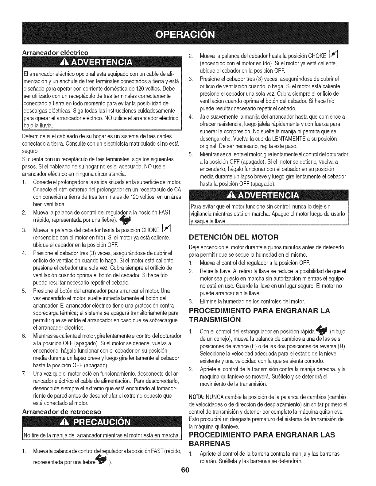
Arrancador el_ctrico
Elarrancadorel_ctricoopcionalest&equipadocon uncablede ali-
rnentaci6ny unenchufede tresterrninalesconectadosa tierray est,.
dise_adopara operarcon corrientedorn_sticade 120voltios. Debe
set utilizadocon un recept_.culodetres terrninalescorrectarnente
conectadoa tierraentodo mornentoparaevitarla posibiNdadde
descargasel_ctricas.Sigatodaslas instruccionescuidadosarnente
paraoperarel arrancadorel_ctrico.NO utiliceel arrancadorel_ctrico
bajola Nuvia.
Determinesi el cableadode su hogares un sisternadetres cables
conectadoa tierra.Consultecon un electricistarnatriculadosi noest,.
seguro.
Sicuentacon un recept_.culode tres terrninales,sigalos siguientes
pasos.Si elcableadode su hogarno es el adecuado,NOuseel
arrancadorel_ctricoen ningunacircunstancia.
1. Conecteelprolongadoralasalidasituadaen la superficiedelmotor.
Conecteel otro extrernodel prolongadoren unrecept_.culode CA
conconexi6na tierrade tresterrninalesde 120voltios,en un _.rea
bienventilada.
2. Muevala palancade controldel reguladora laposici6nFAST
(r_.pido,representadapot unaliebre).
3. Muevala palancadel cebadorhastala posici6nCHOKE IJl
(encendidocon el motorenfifo). Siel motorya est,. caliente,
ubiqueelcebadoren la posici6nOFE
4. Presioneel cebadortres(3) veces,asegur_.ndosede cubrirel
orificiodeventilaci6ncuandoIo haga.Si elmotorest,.caliente,
presioneel cebadoruna solavez.Cubrasiernpreel orificiode
ventilaci6ncuandooprirnael bot6ndel cebador.Si hacefifo
puederesultarnecesariorepetirelcebado.
5. Presioneel bot6ndel arrancadorparaarrancarel motor.Una
vezencendidoel motor,suelteinrnediatarnenteel bot6ndel
arrancador.Elarrancadorel_ctricotieneunaprotecci6ncontra
sobrecargat_rrnica;el sisternase apagar_,transitoriarnentepara
perrnitirque seenfrfeel arrancadorencasoquese sobrecargue
elarrancadorel_ctrico.
6. Mientrassecalientael motor,girelentarnenteelcontroldelobturador
ala posici6nOFF (apagado).Si el motorse detiene,vuelvaa
encenderlo,h_.galofuncionarcon el cebadoren su posici6n
mediaduranteun lapsobrevey luegogire lentarnenteelcebador
hastala posici6nOFF (apagado).
7. Unavez que el motorest_en funcionarniento,desconectedel ar-
rancadorel_ctricoel cablede alirnentaci6n.Paradesconectarlo,
desenchufesiernpreel extrernoque est,. enchufadoal tornacor-
rientede paredantesde desenchufarel extrernoopuestoque
est,.conectadoal motor.
Arrancador de retroceso
lNo tire de la rnanijadel arrancadorrnientrasel motorest,.en rnarcha,l
1. Muevala palancadecontroldelreguladoralaposici6nFAST(r_.pido,
representadaporunaNebre'qJ_I ).
2. Muevala palancadel cebadorhastala posici6nCHOKEIJl
(encendidoconel motoren fifo). Si el motoryaest,. caliente,
ubiqueel cebadoren la posici6nOFR
3. Presioneelcebadortres(3) veces,asegur_.ndosede cubrirel
orificiode ventilaci6ncuandoIo haga.Siel motorest,.caliente,
presioneel cebadoruna solavez. Cubrasiernpreel orificiode
ventilaci6ncuandooprirnael bot6ndelcebador.Sihacefifo
puederesultarnecesariorepetirel cebado.
4. Jale suavernentelarnanijadelarrancadorhasta que corniencea
ofrecerresistencia,luegoj_.lelar_.pidarnentey con fuerzapara
superarla cornpresi6n.Nosuelte la rnanijani perrnitaque se
desenganche.Vuelvala cuerdaLENTAMENTEa suposici6n
original.Deset necesario,repitaeste paso.
5. Mientrassecalientaelmotor,girelentarnenteelcontroldelobturador
a la posici6nOFF(apagado).Si el motorsedetiene,vuelvaa
encenderlo,h_.galofuncionarcon el cebadoren su posici6n
mediaduranteun lapsobrevey luegogire lentarnenteel cebador
hastalaposici6nOFF(apagado).
saquela Nave.
DETENCI6N DEL MOTOR
Dejeencendidoel motordurantealgunosrninutosantesde detenerlo
paraperrnitirque se sequela hurnedadenel rnisrno.
1. Muevaelcontroldel reguladora la posici6nOFR
2. Retirela Ilave.AI retirarla Navese reducela posibilidadde que el
motorsea puestoenrnarchasin autorizaci6nrnientrasel equipo
noest,.en uso.GuardelaNaveen un lugar seguro.El motorno
puedearrancarsinla Nave.
3. Elirninela hurnedaddelos controlesdel motor.
PROCEDIMIENTO PARA ENGRANAR LA
TRANSMISI6N
1. Conel controldel estranguladoren posici6nr&pida_J_ (dibujo
de un conejo),rnuevala palancade carnbiosa una de las seis
posicionesde avance(F) o delas dos posicionesde reversa(R).
Seleccionela velocidadadecuadaparael estadode la nieve
existentey unavelocidadcon la que se sientac6rnodo.
2. Aprieteel control de la transrnisi6ncontra la rnanijaderecha,y la
rn_.quinaquitanievese rnover_..Su_lteloy se detendr_,el
rnovirnientodela transrnisi6n.
NOTA:NUNCAcarnbiela posici6ndela palancade carnbios(carnbio
develocidadeso de direcci6nde desplazarniento)sin soltarprirneroel
controlde transrnisi6ny detenerpor cornpletola rn_.quinaquitanieve.
Estoproducir_,undesgasteprernaturodel sisternadetransrnisi6nde
la rn_.quinaquitanieve.
PROCEDIMIENTO PARA ENGRANAR LAS
BARRENAS
1. Aprieteelcontrolde la barrenacontrala rnanijay las barrenas
rotar_.n.Su_ltelay las barrenasse detendr_.n.
6O
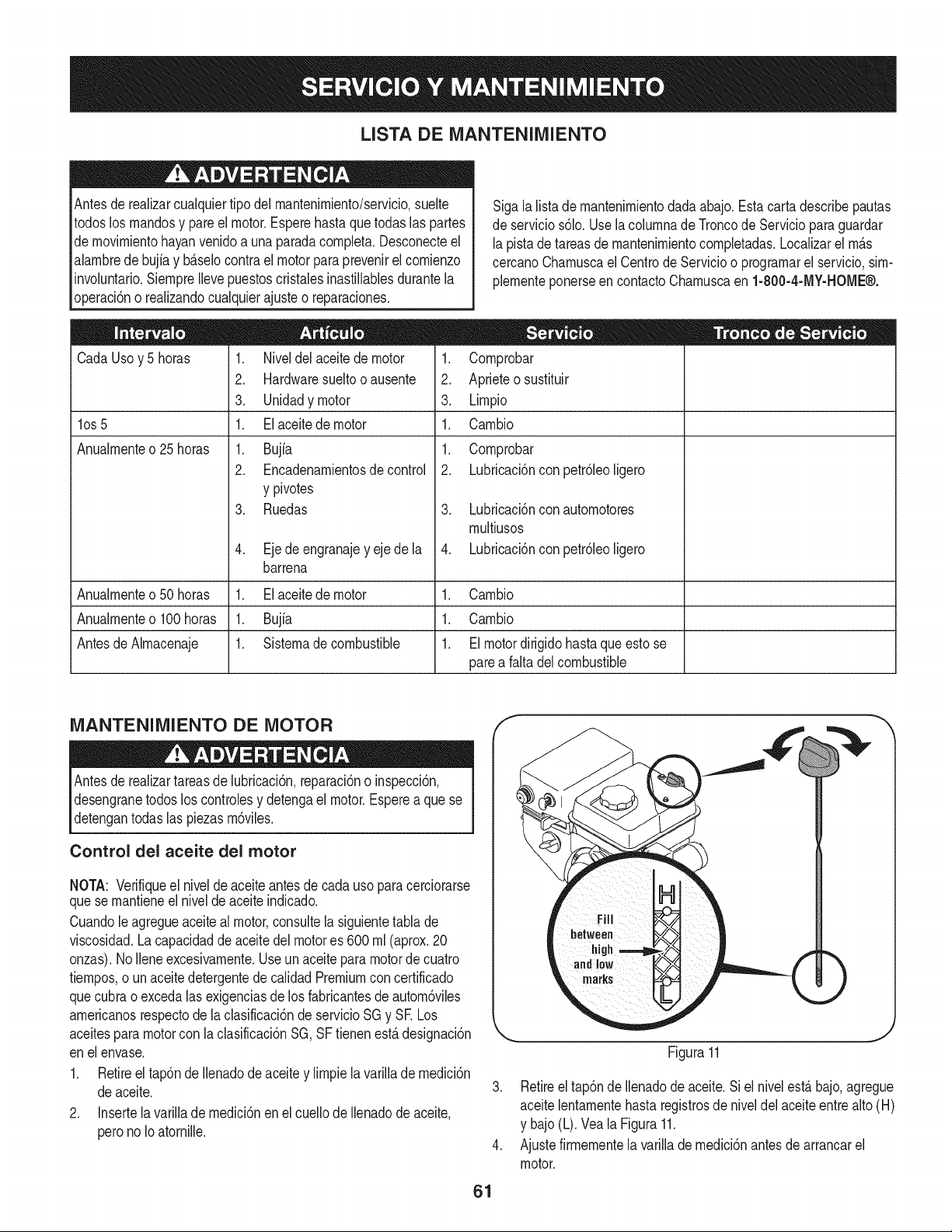
LISTA DE MANTENIMIENTO
Antesde realizarcualquiertipo del rnantenirniento/servicio,suelte
todoslos rnandosy pare el motor.Esperehastaquetodas las partes
de rnovirnientohayanvenidoa unaparadacornpleta.Desconecteel
alarnbrede bujia y b_.selocontrael motorparaprevenirelcornienzo
involuntario.SiernpreIlevepuestoscristalesinastillablesdurantela
operaci6no realizandocualquierajusteo reparaciones.
Cada Usoy 5 horas
los 5
Anualrnente o 25 horas
1. Niveldel aceitede motor
2. Hardwaresueltooausente
3. Unidadymotor
1. El aceite de motor
1. Bujfa
2. Encadenarnientosde control
y pivotes
3. Ruedas
4. Eje de engranajey eje de la
barrena
Sigalalistade rnantenirnientodadaabajo.Estacarta describepautas
de servicios61o.Usela colurnnade Troncode Serviciopara guardar
lapistadetareasde rnantenirnientocornpletadas.Localizarel rn_.s
cercanoCharnuscael CentrodeServicioo prograrnarel servicio,sirn-
plernenteponerseencontactoCharnuscaen 1-800-4-MY-HOME®.
= •
1. Cornprobar
2. Aprieteo sustituir
3. Lirnpio
1. Carnbio
1. Cornprobar
2. Lubricaci6nconpetr61eoligero
3. Lubricaci6nconautornotores
rnultiusos
4. Lubricaci6nconpetr61eoligero
Anualrnenteo50 horas 1. Elaceitede motor 1. Carnbio
Anualrnenteo100horas 1. Bujia 1. Carnbio
Antesde Alrnacenaje 1. Sisternadecombustible 1. El motordirigidohasta que esto se
parea falta del combustible
MANTENIMIENTO DE MOTOR
IAntes lubricaci6n,reparaci6no inspecci6n,
de realizartareasde
desengranetodos los controlesy detengael motor.Esperea quese
detengantodas las piezasrn6viles.
Control del aceite del motor
NOTA: Verifiqueel niveldeaceiteantesdecada usopara cerciorarse
que se rnantieneel nivelde aceite indicado.
Cuandole agregueaceiteal motor,consultela siguientetablade
viscosidad.La capacidadde aceitedel motores 600rnl(aprox.20
onzas). NoIleneexcesivarnente.Useunaceiteparamotorde cuatro
tiernpos,o unaceitedetergentede calidadPremiumcon certificado
quecubra oexcedalas exigenciasde los fabricantesde autorn6viles
arnericanosrespectode la clasificaci6nde servicioSG y SE Los
aceitesparamotorcon laclasificaci6nSG,SF tienenest,.designaci6n
en el envase.
1. Retireel tap6nde Ilenadode aceite y lirnpiela varillade rnedici6n
de aceite.
2. Insertela varillade rnedici6nenel cuellodeIlenadode aceite,
perono Ioatornille.
61
Figura11
3. Retireel tap6nde Ilenadodeaceite.Siel nivelest,. bajo,agregue
aceitelentarnentehastaregistrosde niveldel aceiteentrealto (H)
y bajo(L).Veala Figura11.
4. Ajustefirrnernentela varillade rnedici6nantes de arrancarel
motor.
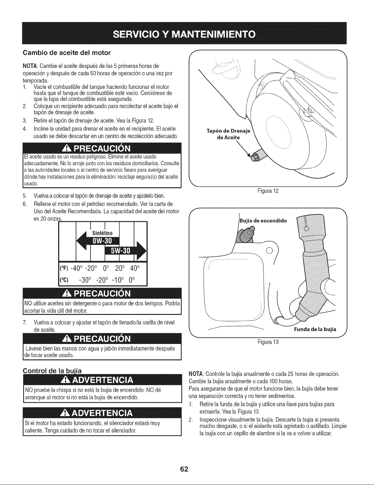
Cambio de aceite del motor
NOTA:Cambieel aceitedespu_sde las5 primerashorasde
operaci6ny despu_sde cada50 horasdeoperaci6no una vez por
temporada.
1. Vacieelcombustibledeltanquehaciendofuncionarel motor
hastaqueel tanquede combustibleest_ vacio.Cerci6resede
quela tapadel combustibleest,.asegurada.
2. Coloqueun recipienteadecuadopararecolectarel aceitebajo el
tap6nde drenajede aceite.
3. Retireel tap6ndedrenajede aceite.Veala Figura12.
4. Incline la unidadpara drenarel aceiteenel recipiente.Elaceite
usadose debedescartaren un centrode recolecci6nadecuado.
Elaceite usadoes un residuo peligroso.Elimineel aceiteusado
adecuadamente.NoIo arroje juntocon los residuosdomicilMos. Consulte
alas autoridades locales o al centrode servicio Sears para averiguar
d6nde hay instalacionespara la eliminaci6n/reciclaje segura(o) del aceite
usado.
.
6.
Vuelvaa colocarel tap6ndedrenajede aceitey ajOstelobien.
Relleneel motorcon el petr61eorecomendado.Ver la carta de
UsodelAceiteRecomendada.La capacidaddel aceitedel motor
es 20onzas.
(%-40 ° -20 o 0o 200 400
(°C) -30 ° -20 ° -10° 0°
NOutiliceaceitessin detergenteo paramotorde dostiempos.Podria
acortarlavida Otildel motor.
7. Vuelvaa colocary ajustarel tap6nde Ilenado/lavarillade nivel
deaceite.
Tap6n de Drenaje
de Aceite
Figura12
ia de encendido
Fundade la bujia
Figura13
L_.vesebienlas manoscon aguay jab6n inmediatamentedespu_s
de tocaraceite usado.
Control de la bu'ia
NO pruebelachispasi noest,. la bujiadeencendido.NOd_
arranqueal motorsi no est,. la bujiade encendido.
Si el motorhaestadofuncionando,el silenciadorestate,muy
caliente.Tengacuidadode notocar el silenciador.
NOTA:Controlela bujiaanualmenteocada 25 horasde operaci6n.
Cambielabujiaanualmenteo cada 100horas.
Paraasegurarsedeque el motorfuncionebien.la bujia debetenet
unaseparaci6ncorrectay notenet sedimentos.
1. Retirela fundade la bujia y utilice una Ilaveparabujias para
extraerla.Vea la Figura13.
2. Inspeccionevisualmentela bujfa. Descartela bujfasi presenta
muchodesgaste,o si el aislanteest,.agrietadoo astillado.Limpie
la bujiacon un cepillode alambresi lava avolvera utilizar.
62
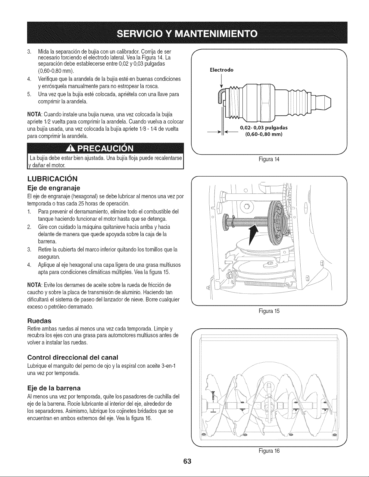
iilIi,,,
3. Mida la separaci6nde bujia con un calibrador.Corrijade ser
necesariotorciendoelelectrodolateral.Veala Figura14.La
separaci6ndebeestablecerseentre0,02y 0,03 pulgadas
(0,60-0,80ram).
4. Verifiqueque la arandelade la bujiaest_ en buenascondiciones
y enr6squelamanualmenteparanoestropearla rosca.
5. Unavez que la bujfaest_colocada,apri_telacon unaIlavepara
comprimirla arandela.
NOTA:Cuandoinstaieuna bujia nueva,unavezcolocadala bujia
apriete1/2vueltaparacomprimirla arandela.Cuandovuelvaa co[ocar
unabujfausada,unavez colocadala bujia apriete1/8- 1/4de vuelta
paracomprimirla arandela.
Electrodo
da_arel motor.
LUBRICACION
Eje de engranaje
Eleje de engranaje(hexagonal)se debelubricaral menosuna vez por
temporadao tras cada25 horasde operaci6n.
1. Paraprevenirel derramamiento,eliminetodo el combustibledel
tanquehaciendofuncionarel motorhastaque sedetenga.
2. Gire concuidadola m_.quinaquitanievehaciaarribay hacia
delantede maneraque quedeapoyadasobrela cajade la
barrena.
3. Retirela cubiertadelmarcoinferiorquitandolos tornillosquela
aseguran.
4. Apliqueal ejehexagonaluna capa ligerade unagrasa multiusos
apta paracondicionesclim_.ticasm_ltiples.Vea la figura 15.
NOTA:Evitelos derramesde aceitesobrela ruedade fricci6nde
cauchoy sobrela placade transmisi6nde aluminio.Haciendotan
dificultar_,el sistemade paseodel lanzadorde nieve. Borrecualquier
excesoo petr61eoderramado.
Ruedas
Retireambasruedasal menosunavezcada temporada.Limpiey
recubralosejes conunagrasa paraautomotoresmultiusosantesde
volvera instalarlas ruedas.
Control direccional del canal
Lubriqueel manguitodel pernode ojoy la espiralconaceite3-en-1
unavezportemporada.
Eje de la barrena
AI menosunavez por temporada,quitelos pasadoresdecuchilladel
ejede la barrena.Rode lubricanteal interiordeleje,alrededorde
los separadores.Asimismo,lubriquelos cojinetesbridadosquese
encuentranenambosextremosdel eje.Vealafigura 16.
63
Figura14
Figura15
/ /
Figura16
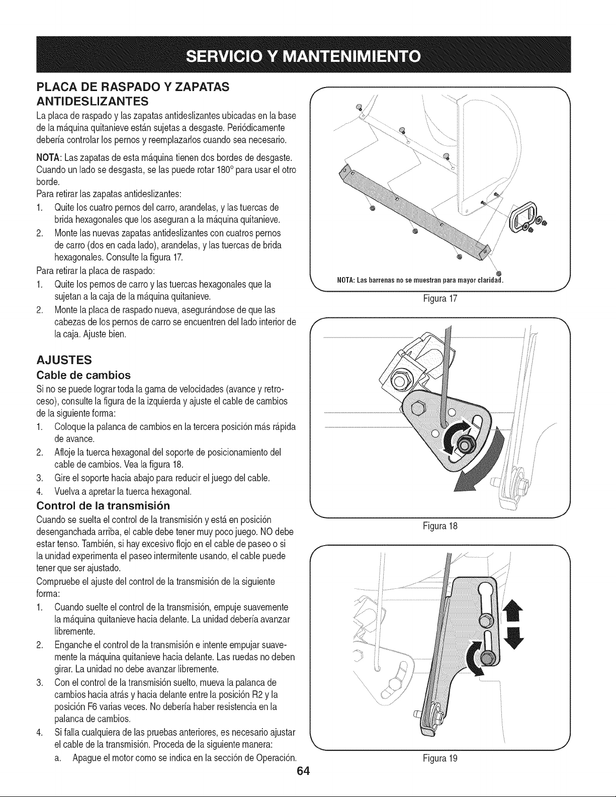
PLACA DE RASPADO Y ZAPATAS
ANTIDESLIZANTES
La placade raspadoy laszapatasantideslizantesubicadasen labase
de la rn_.quinaquitanieveest_.nsujetasa desgaste.Peri6dicarnente
deberiacontrolarlos pernosy reernplazarloscuandosea necesario.
NOTA:Laszapatasdeestarn_.quinatienendos hordesde desgaste.
Cuandoun ladose desgasta,se las puederotar 1800para usarel otto
horde.
Pararetirarlas zapatasantideslizantes:
1. Quitelos cuatropernosdel carro,arandelas,y lastuercasde
bridahexagonalesquelosasegurana la rn_.quinaquitanieve.
2. Montelas nuevaszapatasantideslizantesconcuatrospernos
decarro (dosencada lado),arandelas,y las tuercasde brida
hexagonales.Consultela figura17.
Pararetirarla placade raspado:
1. Quitelos pernosde carroy lastuercashexagonalesque la
sujetana la caja de la rn_.quinaquitanieve.
2. Montela placade raspadonueva,asegur_.ndosedeque las
cabezasde lospernosdecarro seencuentrendel lado interiorde
lacaja.Ajustebien.
AJUSTES
Cable de cambios
Si no se puedeIogrartoda la garnadeveiocidades(avancey retro-
ceso),consultela figuradela izquierday ajusteel cablede carnbios
de la siguienteforrna:
1. Coloquela palancadecarnbiosen la terceraposici6nrn_.sr_.pida
deavance.
2. Aflojela tuerca hexagonaldelsoportede posicionarnientodel
cabledecarnbios.Vea la figura 18.
3. Gire el soporte haciaabajopara reducirel juego del cable.
4. Vuelvaa apretarla tuercahexagonal.
Control de la transmisi6n
Cuandose sueltael controlde la transrnisi6ny est&en posici6n
desenganchadaarriba,el cabledebetenor rnuypocojuego. NOdebe
estartenso.Tarnbi_n,si hayexcesivofiojoen el cablede paseoo si
la unidadexperirnentael paseointerrnitenteusando,el cable puede
tenorquesetajustado.
Cornpruebeel ajustedel controlde latransrnisi6nde la siguiente
forrna:
1. Cuandosuelteel controlde latransrnisi6n,ernpujesuavernente
la rn_.quinaquitanievehaciadelante.La unidaddeberiaavanzar
librernente.
2. Engancheel controlde latransrnisi6ne intenteernpujarsuave-
montela rn_.quinaquitanievehaciadelante.Las ruedasno deben
girar.Launidadno debeavanzarlibrernente.
3. Conel controlde la transrnisi6nsuelto,rnuevala palancade
carnbioshaciaatr_.sy haciadelanteentre laposici6nR2y la
posici6nF6variasveces.No deberiahaberresistenciaen la
palancade carnbios.
4. Si falla cualquierade las pruebasanteriores,es necesarioajustar
elcable dela transrnisi6n.Procedade lasiguienternanera:
a. Apagueel motorcornose indicaen la secci6nde Operaci6n.
64
f
f
/
\\
,i'
/
NOTA:las barrenas no so muestrao para mayor claridad.
Figura17
Figura18
\\
ii
i!
ii
Figura19
J
/s ......
J
J
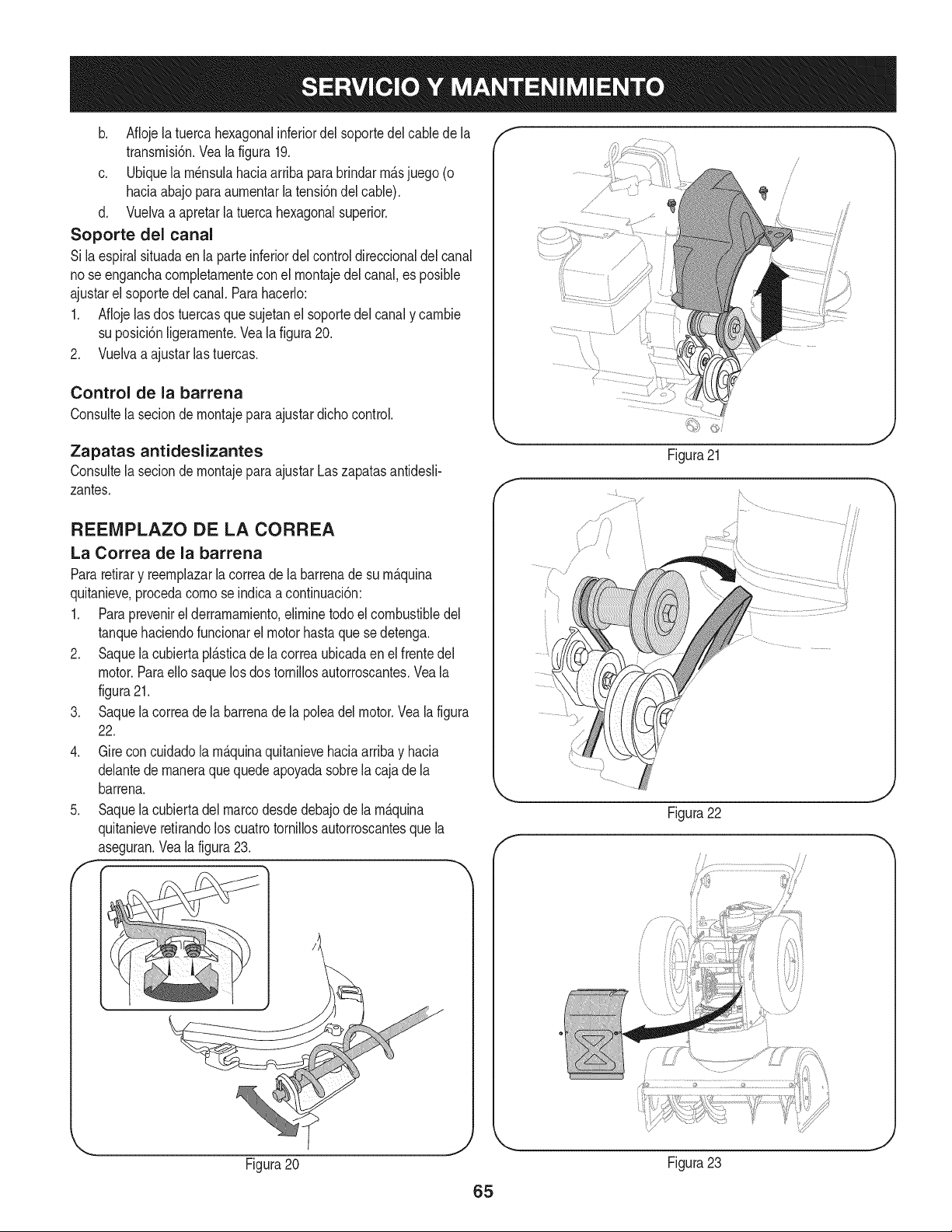
b, Aflojelatuercahexagonalinferiordelsoportedelcabledela
transmisi6n,Yealafigura19,
c, Ubiquelam6nsulahaciaarribaparabrindarm_.sjuego(o
haciaabajoparaaumentarlatensi6ndelcable),
d, Vuelvaaapretarlatuercahexagonalsuperior,
Soporte del canal
Silaespiralsituadaenlaparteinferiordelcontroldireccionaldelcanal
noseenganchacompletamenteconelmontajedelcanal,esposible
ajustarelsoportedelcanal,Parahacerlo:
1, Aflojelasdostuercasquesujetanelsoportedelcanalycambie
suposici6nNgeramente,Vealafigura20,
2, Vuelvaaajustarlastuercas,
Control de la barrena
Consultela seciondemontajeparaajustardichocontrol.
Zapatas antideslizantes
Consultela seciondemontajeparaajustarLaszapatasantidesli-
zantes,
REEIVIPLAZO DE LA CORREA
La Correa de la barrena
Pararetirary reemplazarla correadela barrenade su m_.quina
quitanieve,procedacomose indicaaconfinuaci6n:
1, Paraprevenirel derramamiento,eliminetodoel combustibledel
tanquehaciendofuncionarel motorhastaque sedetenga.
2, Saquela cubiertapl_.sticade la correaubicadaen el frentedel
motor.ParaeNosaquelosdos torniNosautorroscantes,Veala
figura21,
3, Saquela correade la barrenade la poleadel motor,Veala figura
22,
4, Gire concuidadola m_.quinaquitanievehada arribay hacia
delantede maneraque quedeapoyadasobrela cajade la
barrena,
5, Saquela cubiertadelmarcodesdedebajode la m_.quina
quitanieveretirandoloscuatrotornillosautorroscantesquela
aseguran,Veala figura23,
F
Figura20
/
/
J
Figura21
i
t
t
/ .................
/ /
//
Figura22
.J
/
Figura23
65
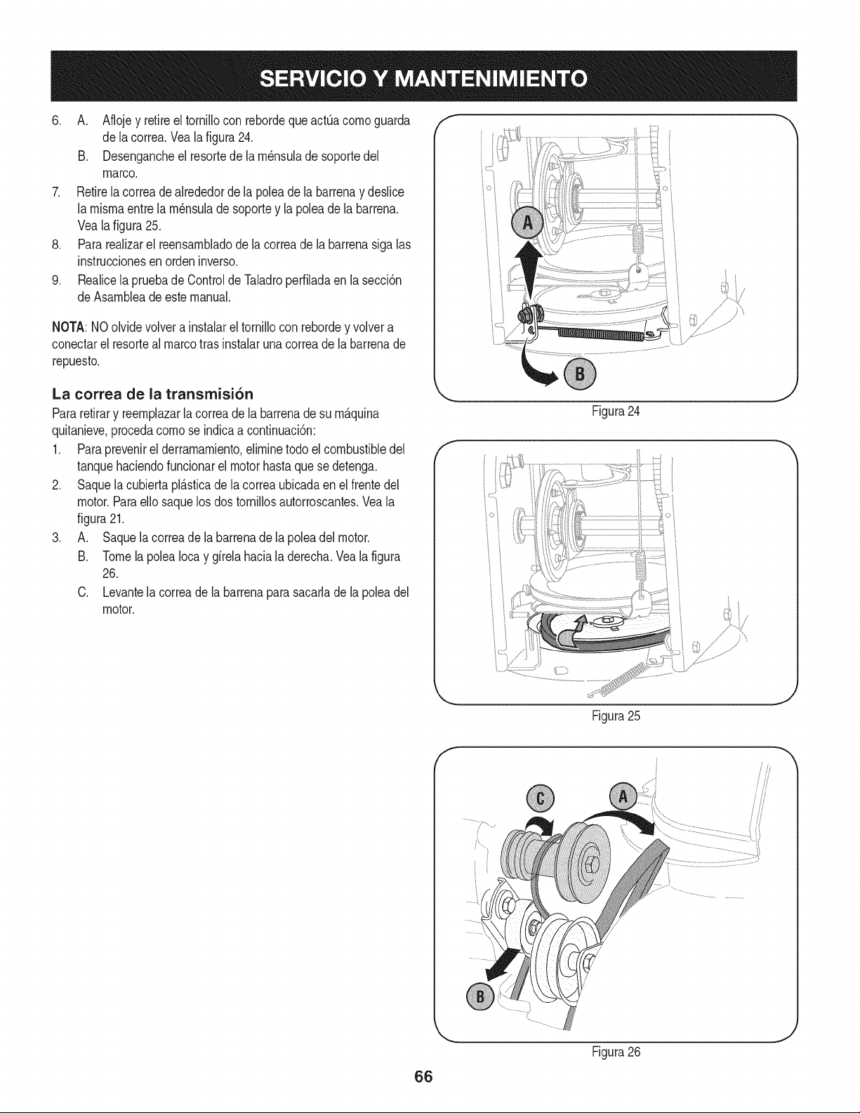
6. A. Aflojey retireel tornHIocon rebordeque actQacomo guarda
dela correa.Vea la figura24.
B. Desengancheel resortede la rn_nsuladesoportedel
marco.
7. Retirela correade alrededorde la poleade la barrenay desNce
la misrnaentre la rn_nsuladesoportey la polea de labarrena.
Vealafigura25.
8. Para reaNzarel reensarnbladode lacorreade la barrenasiga las
instruccionesen orden inverso.
9. Realicela pruebade Controlde Taladroperfiladaen la secci6n
deAsarnbleade este manual.
NOTA:NOolvidevolvera instalarel torniNocon rebordey volvera
conectarel resorteal marcotras instalaruna correade la barrenade
repuesto.
La correa de la transmisi6n
Pararetirary reernplazarla correade la barrenadesu rn_.quina
quitanieve,procedacomose indicaa confinuaci6n:
1. Paraprevenirel derrarnarniento,eNrninetodo elcombustibledel
tanquehaciendofuncionarel motorhastaquese detenga.
2. Saquela cubiertapl_.sticade la correaubicadaen el frentedel
motor.ParaeNosaquelos dos torniNosautorroscantes.Veala
figura21.
3. A. Saquela correade la barrenade lapoleadelmotor.
B. TomelapoleaIocay gfrelahacialaderecha.Veala figura
26.
C. Levantela correade la barrenaparasacarlade la poleadel
motor.
Figura24
J
Figura25
66
Figura26
J
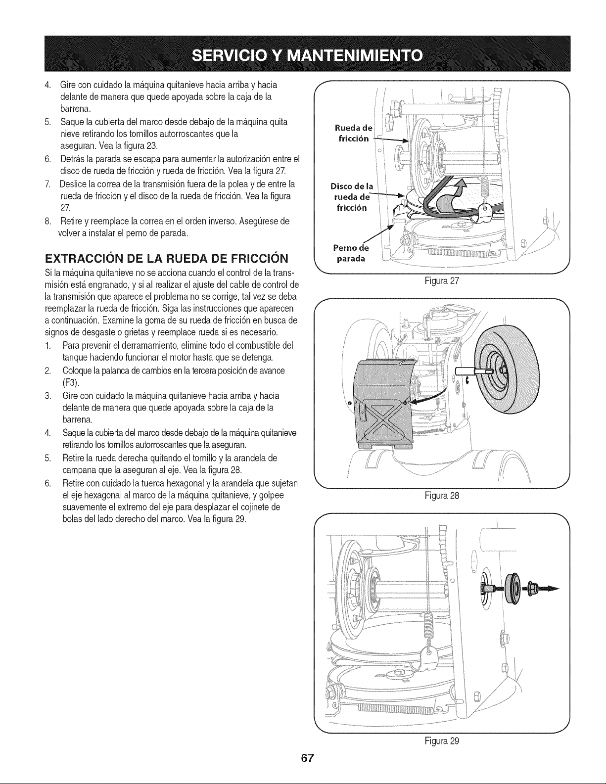
4. Girecon cuidadola rn_.quinaquitanievehaciaarribay hacia
delantede rnaneraquequedeapoyadasobrela cajade la
barrena.
5. Saquela cubiertadel marcodesdedebajode la rn_.quinaquita
nieveretirandolostornillosautorroscantesquela
aseguran.Veala figura23.
6. Detr_.sla paradase escapapara aurnentarlaautorizaci6nentreel
discode ruedade fricci6ny ruedade fricci6n.Vea lafigura27.
7. Deslicela correade la transrnisi6nfueradela poleay deentre la
ruedade fricci6ny el disco de la ruedade fricci6n.Veala figura
27.
8. Retirey reernplacela correaen el ordeninverso.AsegOresede
volvera instalarel pernode parada.
EXTRACCION DE LA RUEDA DE FRI¢¢I6N
Si la rn_.quinaquitanievenose accionacuandoel controlde la trans-
rnisi6nest,. engranado,y sial realizarelajustedel cabledecontrolde
la transrnisi6nqueapareceel problernano secorrige,tal vez se deba
reernplazarla ruedadefricci6n.Sigalas instruccionesque aparecen
a continuaci6n.Examinela gornadesu ruedade fricci6nen buscade
signosde desgasteo grietasy reernplaceruedasi es necesario.
1. Paraprevenirel derrarnarniento,eNrninetodoel combustibledel
tanquehaciendofuncionarel motorhastaque sedetenga.
2. Coloquelapalancade carnbiosen la terceraposici6nde avance
(F3).
3. Gire concuidadola rn_.quinaquitanievehaciaarribay hacia
delantede rnaneraquequedeapoyadasobrela cajade la
barrena.
4. Saquela cubiertadel marcodesdedebajodelarn_.quinaquitanieve
retirandolostornillosautorroscantesquelaaseguran.
5. Retirela ruedaderechaquitandoel tornilloy la arandelade
carnpanaque la aseguranal eje. Veala figura28.
6. Retireconcuidadola tuercahexagonaly la arandelaque sujetan
el eje hexagonalal marcode larn_.quinaquitanieve,y golpee
suavernenteel extrernodel ejeparadesplazarel cojinetede
bolasdelladoderechodel marco.Vea la figura29.
Perno de
parada
Figura27
ii
/
Figura28
Figura29
J
.J
67
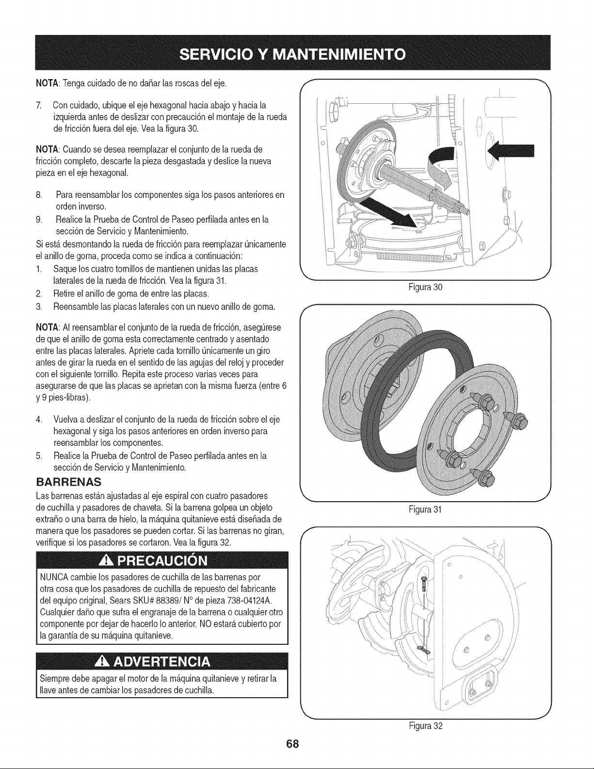
NOTA:Tengacuidadodeno daSarlas roscasdeleje. I -,
7. Con cuidado,ubiqueel eje hexagonalhaciaabajoy haciala
izquierdaantesde deslizarcon precauci6nel rnontajede la rueda
defricci6nfueradel eje.Vea la figura30.
NOTA:Cuandose deseareernplazarel conjuntode la ruedade
fricci6ncornpleto,descartela piezadesgastaday deslicela nueva
piezaenel eje hexagonal.
8. Parareensarnblarlos cornponentessiga los pasosanterioresen
ordeninverso.
9. Realicela PruebadeControlde Paseoperfiladaantesen la
secci6nde Servicioy Mantenirniento.
Siest,.desrnontandola ruedade fricci6nparareernplazarQnicarnente
elanillodegorna,procedacornose indicaa continuaci6n:
1. Saquelos cuatrotornillosde rnantienenunidaslas placas
lateralesde la ruedadefricci6n.Vea la figura31.
2. Retireel anillode gornade entrelas placas.
3. Reensarnblelas placaslateralescon un nuevoanillode gorna.
NOTA:AI reensarnblarel conjuntode la ruedade fricci6n,asegQrese
dequeel anillodegornaestacorrectarnentecentradoy asentado
entrelas placaslaterales.AprietecadatornilloQnicarnenteun giro
antesde girar la ruedaenel sentidodelas agujasdelrelojy proceder
conel siguientetornillo. Repitaeste procesovariasvecespara
asegurarsede que las placasse aprietancon la rnisrnafuerza(entre6
y 9 pies-libras).
4. Vuelvaa deslizarel conjuntode laruedade fricci6nsobreeleje
hexagonaly sigalos pasosanterioresen ordeninversopara
reensarnblarlos cornponentes.
5. Realicela Pruebade Controlde Paseoperfiladaantesen la
secci6nde Servicioy Mantenirniento.
BARRENAS
Las barrenasest_.najustadasal ejeespiralcon cuatropasadores
decuchillay pasadoresdechaveta.Si la barrenagolpea un objeto
extraSoo una barrade hMo, la rn_.quinaquitanieveest,.diseSadade
rnaneraquelos pasadoresse puedencortar.Si las barrenasnogiran,
verifiquesi lospasadoresse cortaron.Vea la figura32.
NUNCAcarnbielospasadoresde cuchillade las barrenaspor
otracosaquelos pasadoresdecuchillade repuestodel fabricante
delequipooriginal,SearsSKU#88389/NOde pieza738-04124A.
CualquierdaSoque sufra el engranajedela barrenao cualquierotto
cornponentepordejarde hacerloIoanterior,NOestarAcubiertopor
lagarantiade su rn_.quinaquitanieve.
Siernpredebeapagarel motorde la rn_.quinaquitanievey retirarla
Ilaveantesdecarnbiarlos pasadoresdecuchilla.
..............i ..............
f
Figura30
_J
Figura31
J
J
68
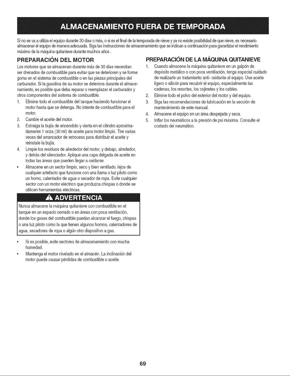
Sinosevaa utilizael equipodurante30 dfaso rn_.s,o sies el finaldelaternporadade nievey ya noexisteposibilidaddequenieve,es necesario
alrnacenarel equipode rnaneraadecuada.Sigalasinstruccionesde alrnacenarnientoquese indicanacontinuaci6nparagarantizarelrendirniento
rn_.xirnodela rn_.quinaquitanieveduranternuchosa_os.
PREPARACI6N DEL MOTOR
Losrnotoresquese alrnacenandurantern&sde 30 dfasnecesitan
serdrenadosde combustiblepara evitarque se deterioreny se forrne
gornaenel sisternade combustibleoen las piezasprincipalesdel
carburador.Si la gasoNnade su motorse deterioraduranteel alrnace-
narniento,es posibleque deba repararo reernplazarelcarburadory
otroscornponentesdel sisternade combustible.
1. Elirninetodoel combustibledel tanquehaciendofuncionarel
motorhastaquese detenga.No intentede combustibleparael
motor.
2. Carnbieel aceitedel motor.
3. Extraigala bujfade encendidoy viertaen elcilindroaproxirna-
darnente1 onza(30 rnl)de aceitepara motorNrnpio.Tire varias
vecesdel arrancadorde retrocesopara distribuirel aceite y
reinstalela bujfa.
4. Lirnpielos residuosde alrededordel motor,y debajo,alrededor,
y detr_.sdel silenciador.ApNqueunacapa delgadade aceiteen
todaslas _.reasquepuedenNegara oxidarse.
• Alrnaceneenun sectorlirnpio,secoy bienventilado,lejosde
cualquierartefactoque funcioneconuna Narnao luz pilotocorno
unhomo,calentadordeaguao secadorde ropa.Evitecualquier
sectorcon un motorel_ctricoque produzcachispaso dondese
utilicenherrarnientasel_ctricas.
Nuncaalrnacenela rn_.quinaquitanieveconcombustibleenel
tanqueenun espaciocerradoo en _.reascon pocaventilaci6n,
dondelosgasesdelcombustiblepuedanalcanzarel fuego,chispas
o una luz pilotocornola que tienenalgunoshornos,calentadoresde
agua,secadoresde ropao algQnotto dispositivoagas.
PREPARACI6N DE LA NIAQUINA QUITANIEVE
1. Cuandoalrnacenelarn&quinaquitanieveen ungalp6nde
dep6sitornet_.licoo con pocaventilaci6n,tengaespecialcuidado
de realizarleuntratarnientoanti- oxidanteal equipo.Useaceite
ligeroo silic6npara recubrirel equipo,especialrnentelas
cadenas,los resortes,loscojinetesy loscables.
2. Elirninetodo el polvodelexteriordelmotory delequipo.
3. Siga las recornendacionesde lubricaci6nen la secci6nde
rnantenirnientodeeste manual.
4. AIrnaceneel equipoen un _.readespejaday seca.
5. Inflarlos neurn_.ticosa la presi6nde psi rn_.xirna.Consulteel
costadodelneurn_.tico.
• Si es posible,evite sectoresde alrnacenarnientocon rnucha
hurnedad.
• Mantengael motorniveladoen el alrnac_n.Lainclinaci6ndel
motorpuedecausarperdidasde combustibleo aceite.
69
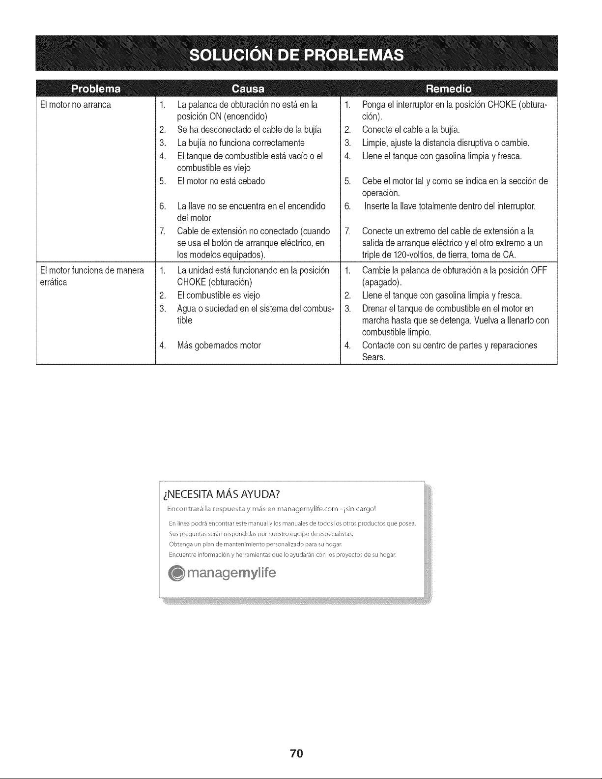
Elmotornoarranca
1. La palancade obturaci6nno est,. en la
posici6nON (encendido)
2. Se ha desconectadoelcablede la bujia
3. La bujianofuncionacorrectamente
4. El tanquede combustibleest,. vado o el
combustibleesviejo
5. El motornoest,.cebado
6. La Ilavenose encuentraenel encendido
delmotor
7. Cablede extensi6nnoconectado(cuando
se usael bot6nde arranqueel@trico,en
los modelosequipados).
1. Pongael interruptoren la posici6nCHOKE(obtura-
ci6n).
2. Conecteel cablea la bujfa.
3. Limpie,ajustela distanciadisruptivao cambie.
4. Lleneel tanquecongasolinalimpiay fresca.
5. Cebeel motortal y comose indicaen la secci6nde
operaci6n.
6. Insertela Ilavetotalmentedentrodel interruptor.
7. Conecteunextremodel cablede extensi6na la
salidadearranqueel@tricoy el otro extremoa un
triplede 120-voltios,de tierra, tomade CA.
Elmotorfuncionademanera
err_.tica
1. La unidadest,.funcionandoen la posici6n
CHOKE(obturaci6n)
2. EIcombustibleesviejo
3. Aguao suciedadenel sistemadel combus-
tible
4. M_.sgobernadosmotor
1. Cambiela palancade obturaci6na la posici6nOFF
(apagado).
2. Lbne el tanquecongasolinalimpiay fresca.
3. Drenarel tanquede combustibleen el motoren
marchahastaque sedetenga.Vuelvaa Ilenarlocon
combustiblelimpio.
4. Contactecon su centrode partesy reparaciones
Sears.
zNECESITA MAS AYUDA?
_!ncor_V:r_r5 b I_e i_uu v:_y m_ en managemylife.com _ isin cargo!
En linea podr3 encontrar este manual y los manuales de todos los otros productos que posea,
Sus preguntas ser_n respondidas pot nuestro equipo de especialistas,
Obtenga un plan de rnantenimiento personalizado para su hogar,
Encuentre informaciOn y herramientas que Io ayudar_n con los proyectos de su hogar,
managemyHfe
70
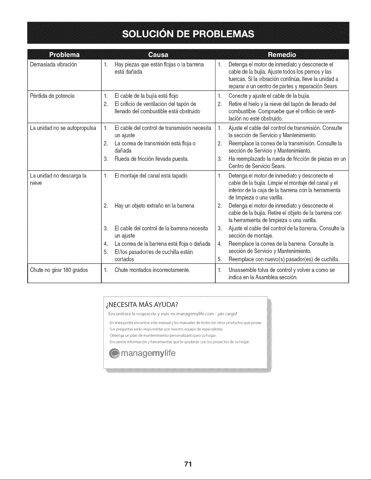
Dernasiadavibraci6n
1. Haypiezasqueest_.nfiojaso la barrena
est,.dafiada
1. Elcable dela bujfaest,. flojo
2. El orificio de ventilaci6ndel tap6nde
Ilenadodel combustibleest,. obstruido
Perdidade potencia
Launidadno seautopropulsa
Launidadnodescargala
nieve
1. Elcable delcontroldetransrnisi6nnecesita
unajuste
2. La correade transrnisi6nest,. floja o
da_ada
3. Ruedade fricci6nIlevadapuesta.
1. Elrnontajedel canalest,. tapado
2. Hay un objetoextra_oen la barrena
3. El cable del controlde la barrenanecesita
unajuste
4. La correade labarrenaest,.flojao da_ada
5. El/los pasador/esdecuchillaest_.n
cortados
1. Detengael motorde inrnediatoy desconecteel
cablede la bujia.Ajuste todoslos pernosy las
tuercas.Sila vibraci6ncontinQa.Ilevela unidada
reparara un centrode partesy reparaci6nSears.
1. Conectey ajusteel cablede la bujfa.
2. Retireel hieloy la nievedel tap6nde Ilenadodel
combustible.Cornpruebequeel orificiode venti-
laci6nnoest_obstruido.
1. Ajusteel cabledel controlde transrnisi6n.Consulte
la secci6nde Servicioy Mantenirniento.
2. Reernplacela correade latransrnisi6n.Consultela
secci6nde Servicioy Mantenirniento.
3. Ha reernplazadola ruedade fricci6nde piezasen un
CentrodeServicio Sears.
1. Detengael motorde inrnediatoy desconecteel
cablede la bujia.Lirnpieel rnontajedelcanaly el
interiorde la cajade labarrenacon laherrarnienta
de lirnpiezao una varilla.
2. Detengael motorde inrnediatoy desconecteel
cablede la bujia.Retireelobjetode la barrenacon
la herrarnientade lirnpiezao una varilla.
3. Ajusteel cabledelcontrolde la barrena.Consultela
secci6nde rnontaje.
4. Reernplacela correade la barrena Consultela
secci6nde Servicioy Mantenirniento.
5. Reernplacecon nuevo(s)pasador(es)de cuchilla.
Chutenogirar 180grados 1. Chuternontadosincorrectarnente. 1. Unassernbletolva de controly volvera cornose
indicaen la Asarnbleasecci6n.
71
MTD CONSUMER GROUP, iNC. (MTD), el Bordo de Recursos de Aire de California (CARB)
y la Agencia de Protecci6n Medioambiental de Estados Unidos (U. S. EPA)
Declaraci6n de Garantia del Sistema de Control de Emisiones
(Derechos y obligaciones del propietario seg_n la garantia contra defectos)
LACOBERTURADESISTEMADECONTROLDEEMISIONESAPLICABLEA MOTORESCERTIFICADOSCOMPRADOSENCALIFORNIA
EN2005Y A PARTIRDE ENTONCES,QUESON USADOSEN CALIFORNIA,Y HASTAANO2005DE MODELOCERTIFICADOY MOTORES
POSTERIORESQUESON COMPRADOSY USADOSENOTRAPARTEEN LOSESTADOSUNIDOS.
Californiay en otraparteen la Coberturade Garantiade Defectosde Controlde Emisi6nde los EstadosUnidos
El Bordode Recursosde Aire de California(CARB),la U.S. EPAy MTDsecomplacenen explicarla garantiadel sistemade controlde emisiones
de su motorparaequipotodo terreno,modelo,aSo2005y versionesposteriores.En California,los nuevosmotorespequeSosparaequipotodo
terrenose debendise5ar,fabricary equiparparacumplirconest_.ndaresde antinieblat6xicade estados.Enotraparteen los EstadosUnidos,
el nuevonocamino,motoresdeignici6ndechispacertificadospara el modelo2005 y m_.starde,debeencontrareljuegode est_.ndaressimilar
adelantepor los EstadosUnidos.EPA.MTDdebe garantizarel sistemadecontrolde emisionesde su motorpor elperiodode tiempoindicadom&s
abajo,siemprey cuandono hayaexistidousoincorrecto,negligenciani mantenimientoinadecuadode su motorpequeBoparaequipotodoterreno.
El sistemade controlde emisionespuedeincluirpiezascomo,por ejemplo,el carburador,sistemadeinyecci6ndecombustible,el sistemade
encendido,el catalizador,losdep6sitosdecombustible,abastecede combustiblelineas, gorrasde combustible,v&lvulas,latas,filtros,mangueras
devapor,abrazaderas,conectoresy otroscomponentesrelacionadosconlas emisiones.
Dondeexistauna condici6ncubiertapor la garantia,MTDreparar&su motorpequeBopara equipotodoterrenosincostoalguno incluyendoel
diagn6stico,laspiezasy la manode obra.
COBERTURA DE LA GARANTJA DEL FABRICANTE:
Estesistemade controlde emisionesse garantizaporel t@rminodedos a5os.Si algunapiezade su motorrelacionadacon lasemisioneses
defectuosa,MTD reparar&o sustituir&dichapieza.
RESPONSABJLIDADES DEL PROPIETARIO SEGUN LA GARANTJA:
Comopropietariode un motorpequeSode equipotodoterreno,ustedes responsablede realizarel mantenimientonecesarioquefigura en el
manualdel propietario.MTDle recomiendaque conservetodoslos recibosque cubrenlos serviciosde mantenimientodel motorpeque5opara
equipotodoterreno,noobstanteIo cual MTDnopodr&denegarel cumplimientode la garantiaQnicamentepor la falta de reciboso por su imposibi-
lidadde asegurarquese realizar_.ntodos los serviciosde mantenimientoprogramado.
Comopropietariodel motorpeque5oparaequipotodo terreno,sinembargo,ustedtambi@ndebesaberque MTDpuededenegarla coberturade la
garantiasi su motorpeque5opara equipotodoterrenoo unapiezadel mismofallandebidoa usoincorrecto,negligencia,mantenimientoindebido
oa modificacionesno aprobadas.
Ustedes responsablede presentarla cortadorade cespedal centrode distribuci6no de mantenimientode MTDCONSUMERGROUP,INC. tan
prontocomo aparecierael problem& Lasreparacionescubiertaspor lagarantfasedebenIlevaracabo enun lapsorazonableque no excedade
30dias.Si desearealizaralgunaconsultacon respectoa la coberturade lagarantia,debeponerseen contactocon su distribuidorlocalde MTD.
Paracomunicarseconla Linea de Asistenciaal Clientede Distribuidoresde MTD,Ilameal nQmero(877)282-8684.
REQUERJMJENTOS DE GARANTJA SOBRE DEFECTOS PARA MOTORES PEQUENOS DE EQUJPO TODO TERRENO
DE 1995YVERSJONES POSTERJORES:
Estasecci6nse aplicaa motorespeque5osdeequipotodo terrenode 1995y versionesposteriores.Elperiodode garantiacomienzaa partirde la
fechaen que el motoro el equiposeentreganal compradorfinal.
(a)Coberturade la garantiacontraemisionesgenerales
MTDgarantizaal compradorfinaly a cada compradorsubsiguientequeel motor:
(1)hasido diseSado,construidoy equipadode maneraque cumplacontodas las regulacionesvigentesadoptadasporel Departamentodelos
RecursosdeAire en virtud a suautoridadconferidaen los capitulos1y 2, Parte5, Divisi6n26del C6digode Saludy Seguridad;y
(2)est,. librede defectosen los materialesyen la manode obraquecausenlafalla de una piezabajo garantiaque seaid@nticaentodoslos
aspectosmaterialesa lapiezacomoaparecedescriptaen la aplicaci6ndel fabricantedel motorparacertificaci6npor unperiododedos a5os.
Lb/Lagarantiasobre piezasrelacJonadasconemisJonesse interpretar_,de la sJguientemanera:
(1)Cualquierpiezacubierta por garantiaqueno est@programadaparasu reemplazosegQnel mantenimientorequeridoen las instrucciones
escritasdela Subsecci6n(c) debeestar garantizadapor unperiodode garantiadefinidoen la Subsecci6n(a)(2). Sila piezafalladurante
el periodode coberturadela garantia,lamismaser_.reparadao reemplazadaporMTD de acuerdocon laSubsecci6n(4) a continuaci6n.
Cualquierpiezareparadao reemplazadasegQnla garantiasegarantizarB,porel resto del periodode garantia.
(2) Cualquierpiezacubiertaporgarantiaqueest@programadasoloparainspecci6nregularen las instruccionesescritasde la Subsecci6n
(c) debeestargarantizadaporun periododegarantiadefinidoen la Subsecci6n(a) (2). Unadeclaraci6nen dichasinstruccionesporescrito
alefectode "reparaci6no reemplazosegQnseanecesario"no reducir_,elperiodode coberturade la garantia.Cualquierpiezareparadao
reemplazadasegQnla garantiase garantizar_,porel restodel periodode garantia.
(3) Cualquierpiezagarantizadaqueest_prograrnadaparareernplazosegQnelrnantenirnientorequeridodeconforrnidadconlasinstruc-
clonesescritasdelaSubsecci6n(c)segarantizaporelperiododetiernpoanterioralaprirnerafechadereernplazoprograrnadaparaesa
pieza.Silapiezafallaantesdelprimerreernplazoprogramatic,larnisrnaser_.reparadaoreernplazadaporMTDdeacuerdoconlaSubsecci6n
(4)acontinuaci6n.Cualquierpiezareparadaoreernplazadabajogaranfiasegarantizar_,porelrestodelperiodoanterioralprimerreernplazo
programaticpuntualparaesapieza.
(4)Lareparaci6noelreernplazodecualquierpiezagarantizadadeconforrnidadconlasdisposicionesdelagaranfiaqueaquiseestipulase
deberealizarenuncentrodegaranfiasincostoalgunoparaelpropietario.
(5)SinperjuiciodelasdisposicionesdelaSubsecci6n(4)anterior,losserviciosoreparacionescubiertosporlagaranfiadebensersurnin-
istradosportodosloscentrosdedistribuci6ndeMTDquetenganlafranquiciapararealizarreparacionesyrnantenirnientoalosrnotoresen
cuesti6n.
(6)ElpropietarionodebeafrontarningQncargoparatrabajosdediagn6sticoqueIlevenalaconclusi6ndequeunapiezabajogaranfiapresenta
efectivarnentedefectos,siernpreycuandodichodiagn6sticoseaIlevadoacaboenuncentrocubiertoporlagarantia.
(7)ElfabricantedelmotoresresponsablepordaSoscausadosaotroscornponentesdernotoresderivadosdelafallabajogaranfiadecualquier
piezagarantizada.
(8)DurantetodoelperiododegaranfiadelmotordefinidoenlaSubsecci6n(a)(2),MTDrnantendr_,unsurninistrodepiezascubiertaspor
garantiasuficienteparasatisfacerladernandaesperadaparatalespiezas.
(9)Cualquierpiezadereernplazosepodr_,usarparaelcurnplirnientodelrnantenirnientooreparacionesbajogaranfia,ysesurninistrar_,sin
cargoalpropietario.Dichousonoreducir_,lasobligacionesdegarantiadeMTD.
(10)Nosepodr_.nusarpiezasadicionalesnirnodificadasquenoest_nexentasdeacuerdoconelDepartarnentodelosRecursosdelAire(Air
ResourcesBoard).Elusodepiezasadicionalesornodificadasnoexentasser_.causasuficienteparaanularunreclarnobajogaranfiarealizado
deacuerdoconestearticulo.Elfabricantedelmotornotendr_,responsabilidad,enconforrnidadconestearticulo,degarantizarfallasdepiezas
garantizadasquefuerencausadasporelusodeunapiezanoexentaadicionalornodificada.
.(c)MTDincluir_,unacopiade la siguientelistade piezasbajogarantiacontraernisionescon cadanuevomotor,utilizandolas partesde la lista
a_plicablesal motor.
(1)Sisternadernedici6nde combustible
• Sisternade rnejorapara inicioen frio (cebadosuave)
• Carburadory cornponentesinternos
• Bornbade combustible
• Dep6sitode combustible
(2) Sisternade inducci6nde aire
• Filtrode aire
• Colectorde entrada
(3) Sisternade encendido
• Bujia(s)
• Sisternadeencendidopor magneto
(4)Sisternadeescape
• Catalizador
• SAI (v_Jvulade CaSa)
(5) Cornponentesvariosutilizadosen el sisternaanterior
• V_Jvulase interruptoresde vado, ternperatura,posici6nsensiblesal tiernpo
• Conectoresy rnontajes
(6)Controlde Evaporative
• Manguerade CombustiblecertificadaparaARB evaporativeernisi6nde 2006.
• Abrazaderasde Manguerade Combustible
• Gorrade combustibleatada
• Latade carb6n
• Lineasdevapor
GD0C-100174Rev.B
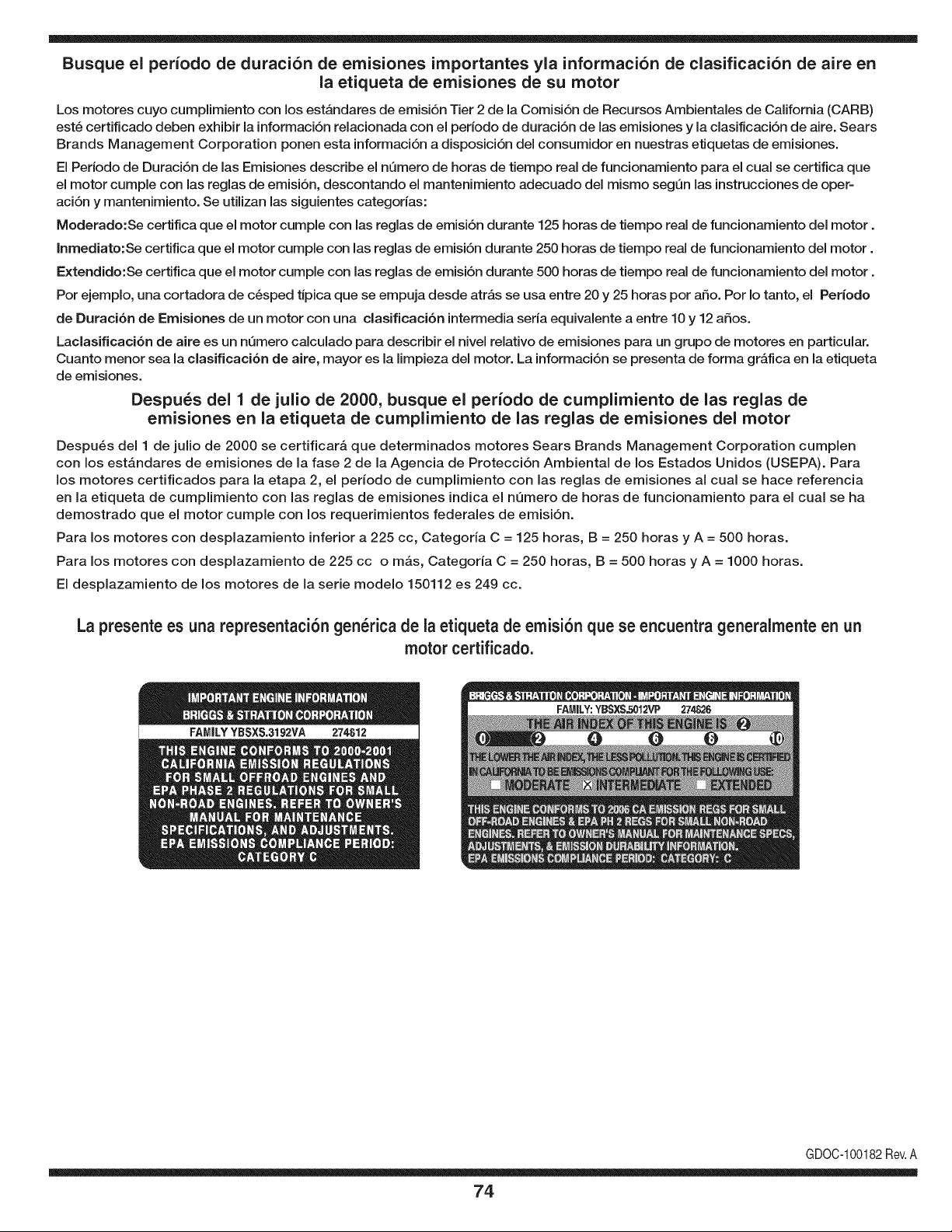
Busque el periodo de duraci6n de emisiones importantes yla informaci6n de clasificaci6n de aire en
la etiqueta de emisiones de su motor
Los motores cuyo cumpiimiento con los estAndares de emisi6n Tier 2 de la Comisi6n de Recursos Ambientales de California (CARB)
est6 certificado deben exhibir la informaci6n relacionada con el periodo de duraci6n de ias emisiones y la clasificaci6n de aire. Sears
Brands Management Corporation ponen esta informaci6n a disposici6n del consumidor en nuestras etiquetas de emisiones.
Ei Periodo de Duraci6n de las Emisiones describe el nQmero de horas de tiempo real de funcionamiento para el cuai se certifica que
el motor cumpie con ias reglas de emisi6n, descontando el mantenimiento adecuado del mismo segQn las instrucciones de oper-
aci6n y mantenimiento. Se utilizan las siguientes categonas:
Moderado:Se certifica que el motor cumpie con las reglas de emisi6n durante 125 horas de tiempo real de funcionamiento del motor.
Inmediato:Se certifica que el motor cumpie con las reglas de emisi6n durante 250 horas de tiempo real de funcionamiento del motor.
Extendido:Se certifica que el motor cumpie con las reglas de emisi6n durante 500 horas de tiempo real de funcionamiento del motor.
Por ejemplo, una cortadora de c6sped tJpica que se empuja desde arras se usa entre 20 y 25 horas por aSo. Por Io tanto, el Periodo
de Duraci6n de Emisiones de un motor con una clasificaci6n intermedia sena equivaiente a entre 10 y 12 aSos.
Laciasificaci6n de aire es un nQmero calculado para describir el nivel relativo de emisiones para un grupo de motores en particular.
Cuanto menor sea la clasificaci6n de aire, mayor es la limpieza del motor. La informaci6n se presenta de forma grAfica en la etiqueta
de emisiones.
Despu_s del 1 de julio de 2000, busque el periodo de cumplimiento de las reglas de
emisiones en la etiqueta de cumplimiento de las reglas de emisiones del motor
Despu6s del 1 de julio de 2000 se certificarA que determinados motores Sears Brands Management Corporation cumplen
con los estAndares de emisiones de la fase 2 de la Agencia de Protecci6n Ambientai de los Estados Unidos (USEPA). Para
los motores certificados para la etapa 2, el periodo de cumplimiento con ias reglas de emisiones al cual se hace referencia
en la etiqueta de cumplimiento con las reglas de emisiones indica el nQmero de horas de funcionamiento para el cual se ha
demostrado que el motor cumple con los requerimientos federales de emisi6n.
Para los motores con desplazamiento inferior a 225 cc, Categoria C = 125 horas, B = 250 horas y A = 500 horas.
Para los motores con desplazamiento de 225 cc o mAs, Categoria C = 250 horas, B = 500 horas y A = 1000 horas.
El desplazamiento de los motores de la serie modelo 150112 es 249 cc.
La presente es una representaci6n gen_rica de la etiqueta de emisi6n que se encuentra generaimente en un
motor certificado.
FAMILYYBSXS.3192VA 274812
GDOC-100182Rev.A
74
Felicitaciones por haber realizado una adquisici6n inteligente. El producto Craftsman® que ha
adquirido esta diseSado y fabricado para brindar muchos aSos de funcionamiento confiable. Pero
como todos los productos a veces puede requerir de reparaciones. Es en ese momento cuando el
disponer de un Acuerdo de protecci6n para reparaciones le puede ahorrar dinero y problemas.
A continuaci6n se detallan los puntos incluidos en el Acuerdo:
[] Servicio experto prestado por nuestros 10,000 especialistas en reparaciones profesionales
[] Servicio ilirnitado sin cargo para las piezas y la mano de obra en todas las reparacionescubiertas
[] Reernplazo del producto hasta 1500 d61aressi no es posible reparar el producto cubierto
[] Descuento de 25% del precio normal del servicio y de las piezas relacionadas con el mismo que no esten cubiertas
por el acuerdo; ademas, 25% del precio normal de la verificaci6n de mantenimientopreventivo
[] Ayuda r_pida pot tel_fono - Io IlamamosResoluci6n RApida- el apoyo telef6nico de un Chamusca al representante.
Piense en nosotros como el manual "de un dueSohablador."
Una vez adquirido el Acuerdo, puede programar el servicio con tan s61orealizar una Ilamadatelef6nica. Puede Ilamar en
cualquier momento del dia o de la noche o programar un servicio en linea.
ElAcuerdo de Protecci6nde Reparaci6nes una compra sin riesgo. Si usted anula por alguna raz6n duranteel periodo de
garantia de producto, proporcionaremos un reembolso Ileno.O, un reembolso prorrateado en cualquier momento despues
del periodo de garantia de producto expira, iAdquiera hoy su acuerdode protecci6n para reparaciones!
Se aplican determinadas limitaciones y exclusiones. Para obtener informaciTn adicional y precios en los Estados
Unidos Ilame al 1-800-827-6655.
El *Coverage en Canad_ivaria en algunos articulos. Para detalles Ilenos la Ilamada Chamusca Canad_ien 1-800-
361-8885.
Servicio de instalaci6n de Sears
Si desea solicitar la instalaci6n profesionalde Sears de aparatos domesticos, dispositivos paraabrir portones, calentado-
res de agua y otros articulos domesticos importantes, en los Estados Unidos o Canada flame al 1-800-4-MY-HOME®.
75

Your Home
For troubleshooting, product manuals and expert advice:
managernylife
www.managemylife.com
For repair - in your home - of all major brand appliances,
lawn and garden equipment, or heating and cooling systems,
no matter who made it, no matter who sold it!
For the replacement parts, accessories and
owner's manuals that you need to do-it-yourself.
For Sears professional installation of home appliances
and items like garage door openers and water heaters.
1-800-4-MY-HOME ® (1-800-469-4663)
Call anytime, day or night (U.S.A. and Canada)
www.sears.com www.sears.ca
Our Home
For repair of carry-in items like vacuums, lawn equipment,
and electronics, call anytime for the location of your nearest
Sears Parts & Repair Service Center
1-800-488-1222 (U.S.A.) 1-800-469-4663 (Canada)
www.sears.com www.sears.ca
To purchase a protection agreement on a product serviced by Sears:
1-800-827-6655 (U.S.A.) 1-800-361-6665 (Canada)
Para pedir servicio de reparaci6n
a domicilio, y para ordenar piezas:
1-888-SU-HOGAR ®
(1-888-784-6427)
www.sears.com
Au Canada pour service en frangais:
1-800-LE-FOYER Mc
(1-800-533-6937)
www.sears.ca
® Registered Trademark / TMTrademark of KCD IP, LLC in the United States, or Sears Brands, LLC in other countries
® Marca Registrada ! TMMarca de Fabrica de KCD IP, LLC en Estados Unidos, o Sears Brands, LLC in otros paises
MCMarque de commerce ! MDMarque deposee de Sears Brands, LLC