Operator's Manual
CRRFTSMRN
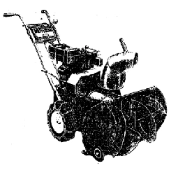
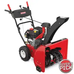
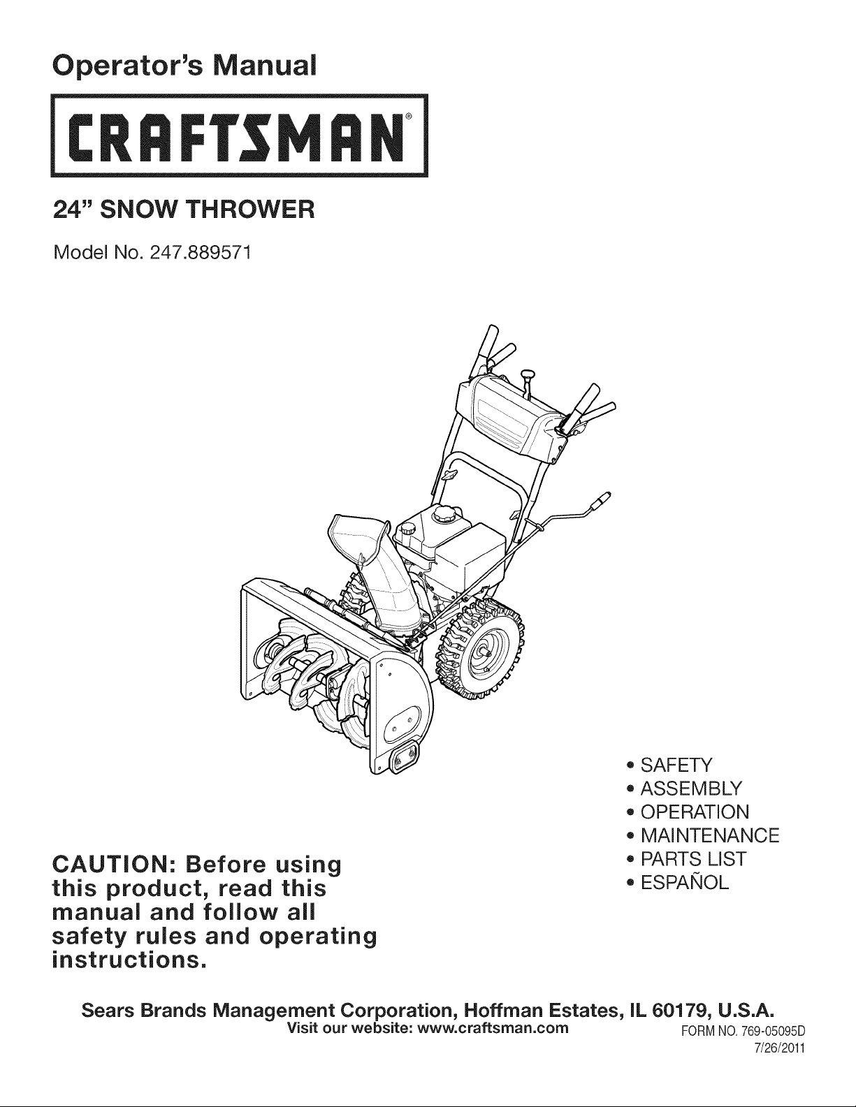
24" SNOW THROWER
Model No. 247.889571
CAUTION: Before using
this product, read this
manual and follow all
safety rules and operating
instructions.
o SAFETY
ASSEMBLY
OPERATION
MAINTENANCE
PARTS LIST
o ESPANOL
Sears Brands Management Corporation, Hoffman Estates, IL 60179, U.S.A.
Visit our website: www.craftsman.com FORM1/0.769-05095D
7/26/2011
WarrantyStatement.................... Page2
SafeOperationPractices.............. Pages3-6
Assembly......................... Pages8-11
Operation........................ Pages12-15
Service&Maintenance.............. Pages16-23
Off-SeasonStorage................... Page24
Troubleshooting...................... Page25
PartsList......................... Pages26-42
RepairProtectionAgreement............ Page47
Espa_ol............................. Page48
CRAFTSMANTWOYEARFULL WARRANTY
FORTWOYEARSfromthedateofpurchase,thisproductiswarrantedagainstanydefectsinmaterialorworkmanship.Defectiveproductwill
receivefreerepairorfreereplacementifrepairisunavailable.
Thiswarrantyisvoidifthisproductiseverusedwhileprovidingcommercialservicesorifrentedtoanotherperson.
Forwarrantycoverage details to obtain repairor replacement,visit the website: www.craftsman.com
This warranty covers ONLYdefects in material and workmanship. Warranty coverage does NOTinclude:
• Expendableitemsthatcan wearoutfromnormalusewithinthewarrantyperiod,includingbut not limitedto augers,augerpaddles,drift
cutters,skidshoes,shaveplate, shearpins,sparkplug,air cleaner,belts,and oil filter.
• Standardmaintenanceservicing,oilchanges,or tune-ups.
• Tire replacementor repaircausedby puncturesfrom outsideobjects,such as nails,thorns,stumps,or glass.
Tireor wheelreplacementor repairresultingfromnormalwear,accident,or improperoperationor maintenance.
• Repairsnecessarybecauseof operatorabuse, includingbutnot limitedto damagecausedby over-speedingthe engine,or fromimpacting
objectsthat bendthe frame,augershaft,etc.
• Repairsnecessarybecauseof operatornegligence,includingbut not limitedto,electricaland mechanicaldamagecausedby improper
storage,failureto usethe propergradeandamountof engineoil, or failureto maintainthe equipmentaccordingto the instructionscontained
inthe operator'smanual.
• Engine(fuelsystem)cleaningor repairscausedbyfuel determinedto becontaminatedoroxidized(stale).In general,fuel shouldbeused
within30 daysof itspurchasedate.
Normaldeteriorationandwearof the exteriorfinishes,or productlabelreplacement.
Thiswarrantygivesyou specificlegalrights,and you mayalso haveotherrightswhichvaryfromstateto state.
Sears Brands Management Corporation, Hoffman Estates, IL 60179
EngineOilType: 5W-30
EngineOilCapacity: 20ounces
FuelCapacity: 2.3Quarts
SparkPlug: F6RTC(951-10292)
SparkPlugGap: .020"to .030"
Model Number.................................................................
Serial Number .................................................................
Dateof Purchase.............................................................
Recordthe modelnumber,serialnumber
anddateof purchaseabove
© KCD IR LLC
2
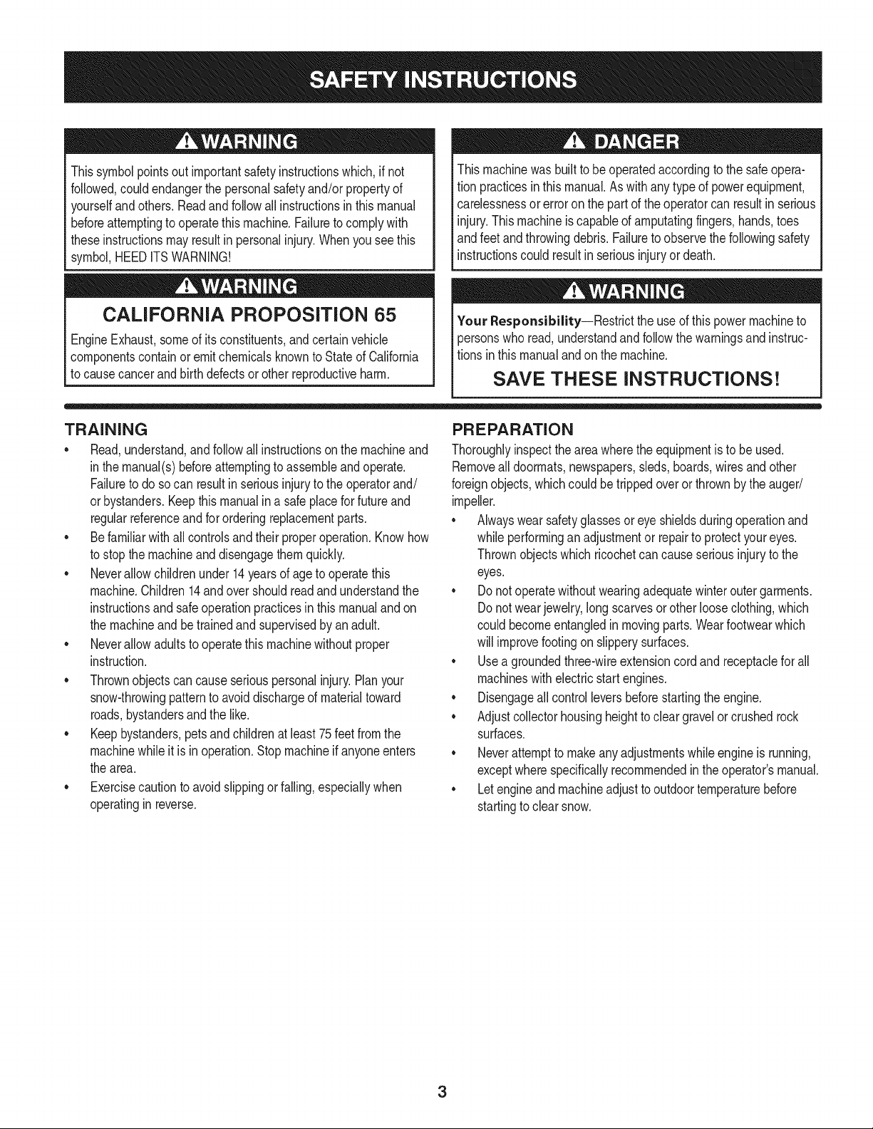
Thissymbolpointsout importantsafetyinstructionswhich,if not
followed,couldendangerthepersonalsafetyand/orpropertyof
yourselfand others. Readand followall instructionsin thismanual
beforeattemptingto operatethismachine.Failureto complywith
theseinstructionsmay resultin personalinjury.Whenyou seethis
symbol,HEEDITSWARNING!
CALIFORNIA PROPOSITION 65
EngineExhaust,someof its constituents,andcertainvehicle
componentscontainor emit chemicalsknownto Stateof California
to cause cancerand birthdefectsorotherreproductiveharm,
Thismachinewasbuiltto be operatedaccordingto the safeopera-
tion practicesin this manual.As withanytypeof powerequipment,
carelessnessor error on the partof the operatorcan resultin serious
injury.Thismachineis capableof amputatingfingers,hands,toes
andfeetandthrowingdebris.Failureto observethe followingsafety
instructionscouldresultin seriousinjuryor death.
Your Responsibility--Restrict the use of thispowermachineto
personswho read,understandandfollowthewarningsand instruc-
tionsin thismanualandon the machine,
SAVE THESE INSTRUCTIONS!
TRAiNiNG
• Read,understand,and followall instructionson the machineand
in themanual(s)beforeattemptingto assembleand operate.
Failureto do socan resultinseriousinjuryto the operatorand/
orbystanders.Keepthis manualin a safe placeforfuture and
regularreferenceand for orderingreplacementparts.
• Befamiliarwith all controlsandtheir properoperation.Knowhow
to stop the machineand disengagethemquickly.
• Neverallowchildrenunder14yearsof age to operatethis
machine.Children14andover shouldreadandunderstandthe
instructionsand safe operationpracticesin thismanualandon
the machineand be trainedand supervisedby anadult.
Neverallowadultsto operatethis machinewithoutproper
instruction.
• Thrownobjectscan causeseriouspersonalinjury.Planyour
snow-throwingpatternto avoiddischargeof materialtoward
roads,bystandersand the like.
Keepbystanders,pets and childrenat least75feetfromthe
machinewhile it is in operation.Stopmachineif anyoneenters
the area.
• Exercisecautionto avoidslippingor falling,especiallywhen
operatingin reverse.
PREPARATION
Thoroughlyinspecttheareawherethe equipmentisto be used.
Removeall doormats,newspapers,sleds,boards,wiresandother
foreignobjects,whichcouldbe trippedoverorthrownby the auger/
impeller.
• Alwayswear safetyglassesor eyeshieldsduringoperationand
while performingan adjustmentor repairto protectyoureyes.
Thrownobjectswhichricochetcancause seriousinjuryto the
eyes.
Donot operatewithoutwearingadequatewinteroutergarments.
Donot wearjewelry,longscarvesorotherlooseclothing,which
could becomeentangledin movingparts.Wearfootwearwhich
will improvefooting on slipperysurfaces.
Usea groundedthree-wireextensioncordand receptaclefor all
machineswith electricstartengines.
Disengageall controlleversbeforestartingthe engine.
Adjustcollectorhousingheightto cleargravelorcrushedrock
surfaces.
• Neverattemptto makeanyadjustmentswhileengineis running,
exceptwherespecificallyrecommendedinthe operator'smanual.
Letengineandmachineadjustto outdoortemperaturebefore
startingto clearsnow.
3
Safe Handling of Gasoline
Toavoidpersonalinjuryor propertydamageuseextremecare in
handlinggasoline.Gasolineis extremelyflammableandthe vaporsare
explosive.Seriouspersonalinjurycan occurwhengasolineis spilled
onyourselfor yourclotheswhichcan ignite.Washyour skinand
changeclothesimmediately.
• Useonly anapprovedgasolinecontainer.
• Extinguishall cigarettes,cigars,pipesandother sources
of ignition.
• Neverfuelmachineindoors.
• Neverremovegas capor addfuel whilethe engineis hot
or running.
• Allowengineto coolat leasttwo minutesbeforerefueling.
• Neveroverfill fueltank. Filltank to no morethan1/2inch
belowbottomof filler neckto providespacefor fuel
expansion.
• Replacegasolinecap and tightensecurely.
• If gasolineis spilled,wipeit offthe engineandequipment.
Movemachineto anotherarea.Wait5 minutesbefore
startingthe engine.
• Neverstorethe machineor fuel containerinsidewhere
thereis an open flame,sparkor pilotlight (e.g.furnace,
waterheater,space heater,clothesdryer etc.).
• Allowmachineto cool at least5 minutesbeforestoring.
• Neverfill containersinsidea vehicleor ona truckor trailer
bedwitha plasticliner.Alwaysplacecontainersonthe
groundawayfromyourvehiclebeforefilling.
• If possible,removegas-poweredequipmentfrom thetruck
ortrailerand refuelit on the ground.If thisis not possible,
then refuelsuchequipmenton a trailerwitha portable
container,ratherthan from a gasolinedispensernozzle.
• Keepthe nozzleincontactwiththe rimof the fueltankor
containeropeningat alltimesuntil fuelingis complete.Do
notuse a nozzlelock-opendevice.
OPERATION
• Do not puthandsorfeetnear rotatingparts,in the auger/impeller
housingor chuteassembly.Contactwith the rotatingpartscan
amputatehandsandfeet.
• Theauger/impellercontrolleveris a safetydevice.Neverbypass
itsoperation.Doingso makesthe machineunsafeandmaycause
personalinjury.
• Thecontrol leversmustoperateeasilyin bothdirectionsand
automaticallyreturnto the disengagedpositionwhenreleased.
• Neveroperatewith a missingor damagedchuteassembly.Keep
all safetydevicesin placeandworking.
• Neverrunan engine indoorsor ina poorlyventilatedarea. Engine
exhaustcontainscarbonmonoxide,anodorlessanddeadlygas.
• Do notoperatemachinewhileunderthe influenceof alcoholor
drugs.
• Mufflerandenginebecomehotandcan causea burn.Do not
touch.Keepchildrenaway.
• Exerciseextremecautionwhenoperatingon orcrossinggravel
surfaces.Stay alertfor hiddenhazardsor traffic.
• Exercisecautionwhenchangingdirectionandwhileoperatingon
slopes.Do notoperateon steepslopes.
• Planyoursnow-throwingpatternto avoiddischargetowards
windows,walls,carsetc. Thus,avoidingpossibleproperty
damageor personalinjurycausedby a ricochet.
• Neverdirect dischargeat children,bystandersand petsor allow
anyoneinfrontof the machine.
• Donot overloadmachinecapacityby attemptingto clearsnowat
too fastof a rate.
• Neveroperatethis machinewithoutgoodvisibilityorlight.Always
be sureof yourfootingand keepa firmholdon the handles.Walk,
neverrun.
• Disengagepowerto theauger/impellerwhentransportingor not
in use.
• Neveroperatemachineat hightransportspeedson slippery
surfaces.Lookdownand behindand usecare whenbackingup.
• If the machineshouldstart to vibrateabnormally,stopthe engine,
disconnectthe sparkplugwire and groundit againstthe engine.
Inspectthoroughlyfor damage.Repairanydamagebefore
startingandoperating.
• Disengageall controlleversandstopenginebeforeyouleave
the operatingposition(behindthe handles).Waituntilthe auger/
impellercomesto a completestopbeforeuncloggingthechute
assembly,makingany adjustments,or inspections.
• Neverput yourhandinthe dischargeor collectoropenings.Do
not unclogchuteassemblywhileengineis running.Shutoff
engineand remainbehindhandlesuntilall movingpartshave
stoppedbeforeunclogging.
• Useonly attachmentsandaccessoriesapprovedby the manufac-
turer (e.g.wheelweights,tire chains,cabsetc.).
• Whenstartingengine,pullcord slowlyuntilresistanceis felt, then
pull rapidly.Rapidretractionof startercord(kickback)will pull
handandarmtowardenginefasterthan youcan let go. Broken
bones,fractures,bruisesor sprainscould result.
• If situationsoccur whichare notcoveredinthis manual,use care
andgoodjudgment.
• Forin-warrantysafety,operationor maintenancequestions,or to
orderpartsandscheduleservice,call 1-800-4-MY-HOME.
CLEARING A CLOGGED DISCHARGE CHUTE
Handcontactwith the rotatingimpellerinsidethe dischargechute
is the mostcommoncauseof injuryassociatedwithsnowthrowers.
Neveruse yourhand to cleanout thedischargechute.
Toclear thechute:
1. SHUTTHEENGINEOFF!
2. Wait 10secondsto be surethe impellerbladeshavestopped
rotating.
3. Alwaysusea clean-outtool,not yourhands.
4
MAINTENANCE & STORAGE
• Nevertamperwithsafetydevices.Checktheirproperoperation
regularly.Referto the maintenanceandadjustmentsectionsof
thismanual.
• Beforecleaning,repairing,or inspectingmachinedisengageall
controlleversandstopthe engine.Waituntilthe auger/impeller
cometo a completestop.Disconnectthe sparkplugwireand
groundagainsttheengineto preventunintendedstarting.
Checkboltsand screwsfor propertightnessat frequentintervals
to keepthe machinein safeworkingcondition.Also,visually
inspectmachinefor anydamage.
Do notchangetheenginegovernorsettingor over-speedthe
engine.Thegovernorcontrolsthe maximumsafeoperatingspeed
of the engine.
Snowthrowershaveplatesand skidshoesaresubjectto wear
anddamage.Foryoursafetyprotection,frequentlycheckall
componentsand replacewithoriginalequipmentmanufacturer's
(OEM)partsonlyas listed in the Partspagesof thisoperator's
manual.Useof parts which do not meetthe originalequipment
specificationsmayleadto improperperformanceandcompro-
misesafety!
Checkcontrolleversperiodicallyto verifytheyengageanddisen-
gageproperlyand adjust,if necessary.Referto the adjustment
sectioninthisoperator'smanualfor instructions.
Maintainor replacesafetyandinstructionlabels,as necessary.
Observeproperdisposallawsand regulationsfor gas, oil,etc. to
protectthe environment.
Priorto storing,run machinea few minutestoclear snowfrom
machineand preventfreezeupof auger/impeller.
Neverstorethe machineorfuel containerinsidewherethereisan
openflame,spark or pilot lightsuchas a waterheater,furnace,
clothesdryer etc.
Alwaysreferto the operator'smanualfor properinstructionson
off-seasonstorage.
Checkfuelline,tank, cap,andfittingsfrequentlyfor cracksor
leaks.Replaceif necessary.
Do notcrank enginewithspark plug removed.
Accordingto the ConsumerProductsSafetyCommission(CPSC)
andthe U.S.EnvironmentalProtectionAgency(EPA),this product
hasan AverageUsefulLifeof seven(7) years,or 60 hoursof
operation.At the end of theAverageUsefulLifehavethe machine
inspectedannuallybyan authorizedservicedealer to ensurethat
allmechanicaland safetysystemsare workingproperlyand not
wornexcessively.Failureto do so can resultin accidents,injuries
ordeath.
DO NOT MODIFY ENGINE
Toavoidseriousinjuryor death,do not modifyenginein any way.
Tamperingwiththe governorsettingcanleadto a runawayengineand
causeit to operateat unsafespeeds.Nevertamperwithfactorysetting
of engine governor.
NOTICE REGARDING EMiSSiONS
Engineswhich are certifiedtocomplywith Californiaand federal
EPAemissionregulationsfor SORE(SmallOff RoadEquipment)are
certifiedto operateon regularunleadedgasoline,and mayinclude
the followingemissioncontrolsystems:EngineModification(EM),
OxidizingCatalyst(OC), SecondaryAir Injection(SAI)and ThreeWay
Catalyst(TWO)if so equipped.
SPARK ARRESTOR
Thismachineisequippedwithaninternalcombustionengineand
shouldnotbe usedonor nearany unimprovedforest-covered,
brush-coveredor grass-coveredland unlessthe engine'sexhaust
systemisequippedwith a sparkarrestormeetingapplicablelocalor
statelaws(if any)
Ifa sparkarrestoris used,it shouldbe maintainedin effectiveworking
orderby theoperator.Inthe State of Californiathe aboveis required
bylaw (Section4442of the CaliforniaPublicResourcesCode).Other
statesmayhavesimilarlaws. Federallawsapplyonfederallands.
A sparkarrestorfor the muffleris availablethroughyournearestSears
PartsandRepairServiceCenter.
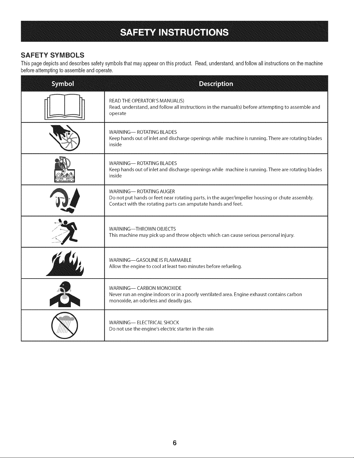
SAFETY SYMBOLS
Thispagedepictsanddescribessafetysymbolsthatmayappearonthisproduct. Read,understand,and followall instructionson the machine
beforeattemptingto assembleandoperate.
. +
i
i
"JIp
READ THE OPERATOR'S MANUAL(S)
Read, understand, and follow all instructions in the manual(s) before attempting to assemble and
operate
WARNING-- ROTATING BLADES
Keep hands out of inlet and discharge openings while machine is running. There are rotating blades
inside
WARNING-- ROTATING BLADES
Keep hands out of inlet and discharge openings while machine is running. There are rotating blades
inside
WARNING-- ROTATING AUGER
Do not put hands or feet near rotating parts, in the auger/impeller housing or chute assembly.
Contact with the rotating parts can amputate hands and feet.
WARNING--THROWN OBJECTS
This machine may pick up and throw objects which can cause serious personal injury.
WARNING--GASOLINE IS FLAMMABLE
Allow the engine to cool at least two minutes before refueling.
WARNING-- CARBON MONOXIDE
Never run an engine indoors or in a poorly ventilated area. Engine exhaust contains carbon
monoxide, an odorless and deadly gas+
WARNING-- ELECTRICAL SHOCK
Do not use the engine's electric starter in the rain
6

Thispageleftintentionallyblank.
7
NOTE:Referencesto rightorleft sideof the snowthrowerare
determinedfrombehindthe unit inthe operatingposition(standing
directlybehindthe snowthrower,facingthe handlepanel).
REMOVING FROM CARTON
1. Cut the cornersof thecartonandlay the sidesflaton the ground.
Removeand discard all packinginserts.
2. Movethe snowthrowerout of thecarton.
3. Makecertainthe cartonhas beencompletelyemptiedbefore
discardingit.
LOOSE PARTS
Tworeplacementaugershearpinsare includedin the handlepanel.
Referto ReplacingShearPinsin the Operationsectionfor more
informationregardingshearpin replacement.
ASSEMBLY
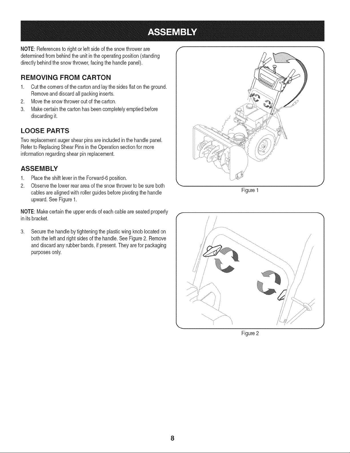
1. Placethe shiftleverin the Forward-6position.
2. Observethe lowerreararea of the snowthrowerto be sure both
cablesarealignedwith rollerguidesbeforepivotingthe handle
upward.See Figure1.
Figure1
NOTE:Makecertainthe upperends of eachcableare seatedproperly
in itsbracket.
.
Securethehandlebytighteningthe plasticwing knoblocatedon
boththe left andrightsidesof the handle.SeeFigure2. Remove
anddiscardany rubberbands,if present.Theyarefor packaging
purposesonly.
f
!
/
/
/
Figure2
8
.
5.
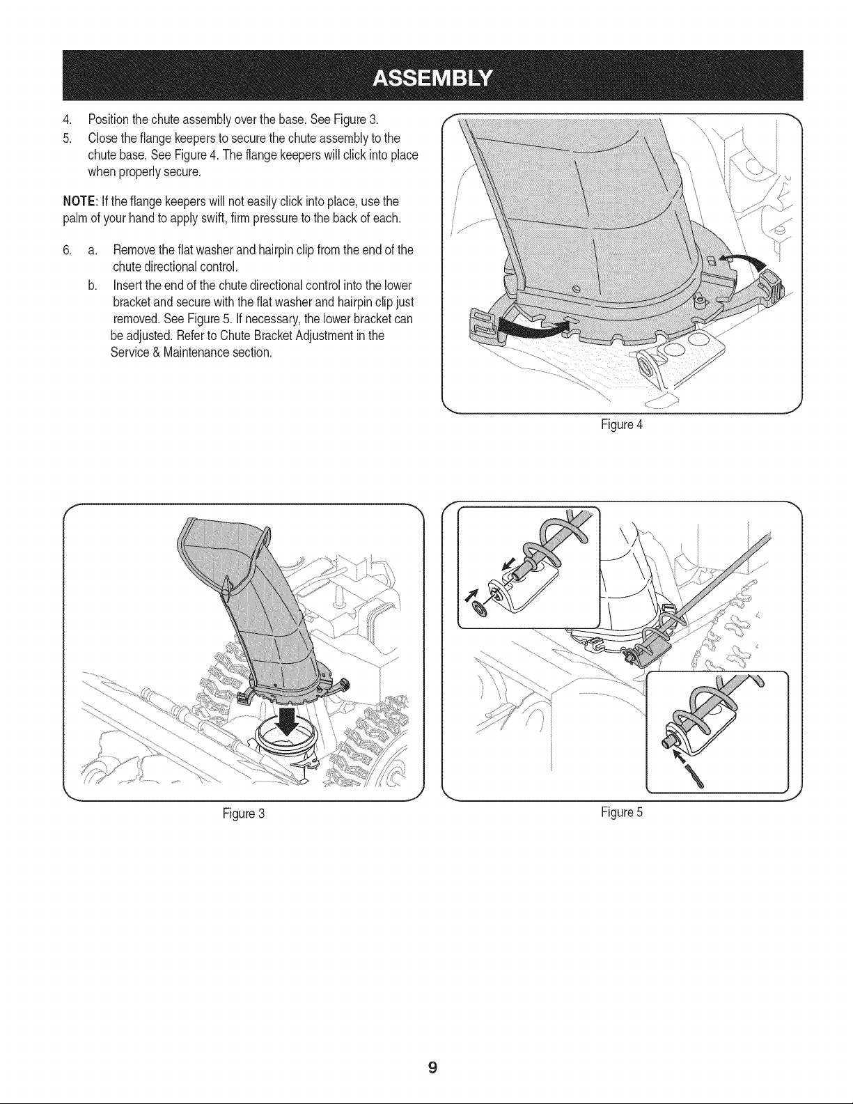
Positionthechuteassemblyoverthe base.See Figure3.
Closethe flangekeepersto securethechuteassemblyto the
chutebase.SeeFigure4. The flangekeeperswill click intoplace
whenproperlysecure.
NOTE:Ifthe flangekeeperswill noteasily clickinto place,usethe
palmof yourhandto applyswift,firm pressureto the backof each.
.
a.
b.
Removetheflat washerand hairpinclip fromthe end of the
chutedirectionalcontrol.
Insertthe endof the chutedirectionalcontrolinto the lower
bracketand securewith the flatwasherandhairpinclipjust
removed.See Figure5. If necessary,the lowerbracketcan
beadjusted.Referto ChuteBracketAdjustmentinthe
Service& Maintenancesection.
Figure4
f F
Figure3
\
J
Figure5
9
SET-UP
Chute Clean-Out Tool
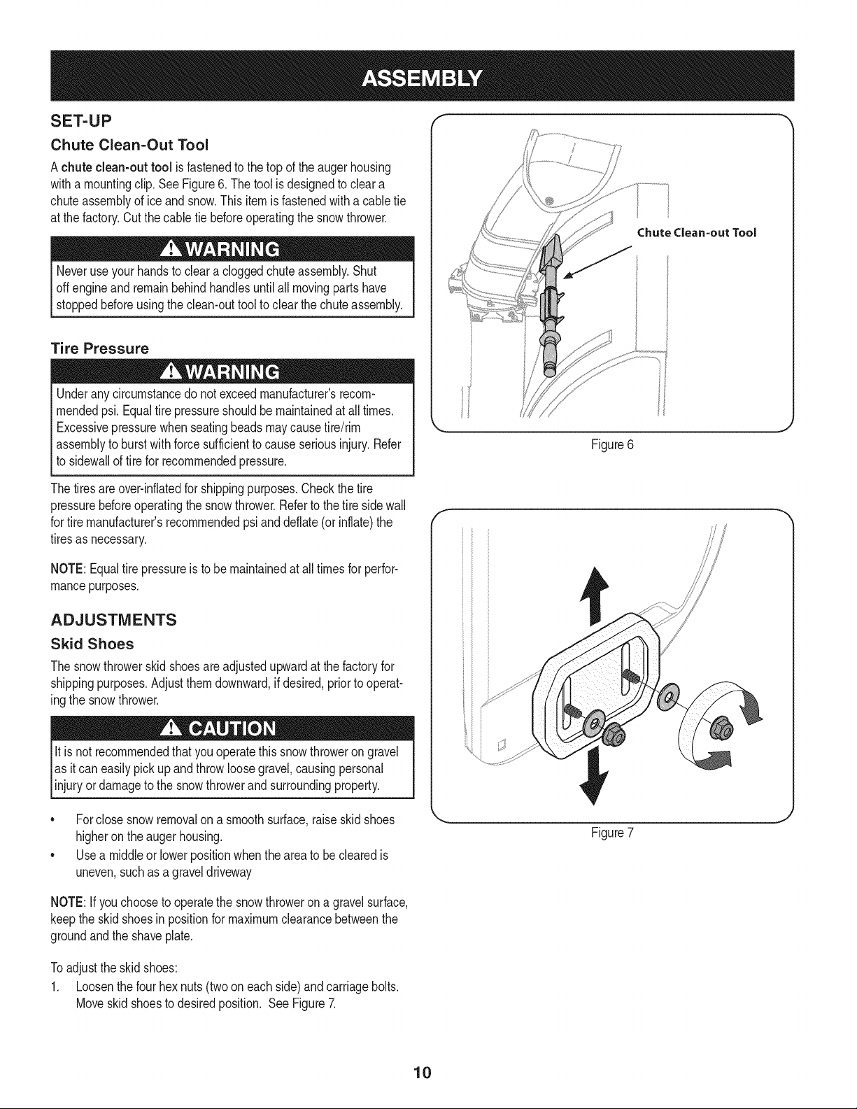
Achute clean-out tool is fastenedto the top of the augerhousing
witha mountingclip.SeeFigure6. The tool is designedto cleara
chuteassemblyof ice andsnow.Thisitem is fastenedwitha cabletie
at the factory.Cut thecable tie beforeoperatingthe snowthrower.
Neveruseyour handsto cleara cloggedchuteassembly.Shut
offengineand remainbehindhandlesuntilall movingpartshave
stoppedbeforeusingthe clean-outtool to clear thechuteassembly.
Tire Pressure
Underanycircumstancedo notexceedmanufacturer'srecom-
mendedpsi. Equaltire pressureshouldbe maintainedat all times.
Excessivepressurewhenseatingbeadsmaycausetire/rim
assemblyto burst with force sufficientto causeseriousinjury.Refer
to sidewallof tirefor recommendedpressure.
Thetiresareover-inflatedfor shippingpurposes.Checkthetire
pressurebeforeoperatingthe snowthrower.Referto the tire sidewall
for tiremanufacturer'srecommendedpsianddeflate(or inflate)the
tiresas necessary.
NOTE:Equaltire pressureis to be maintainedat all timesfor perfor-
mancepurposes.
ADJUSTMENTS
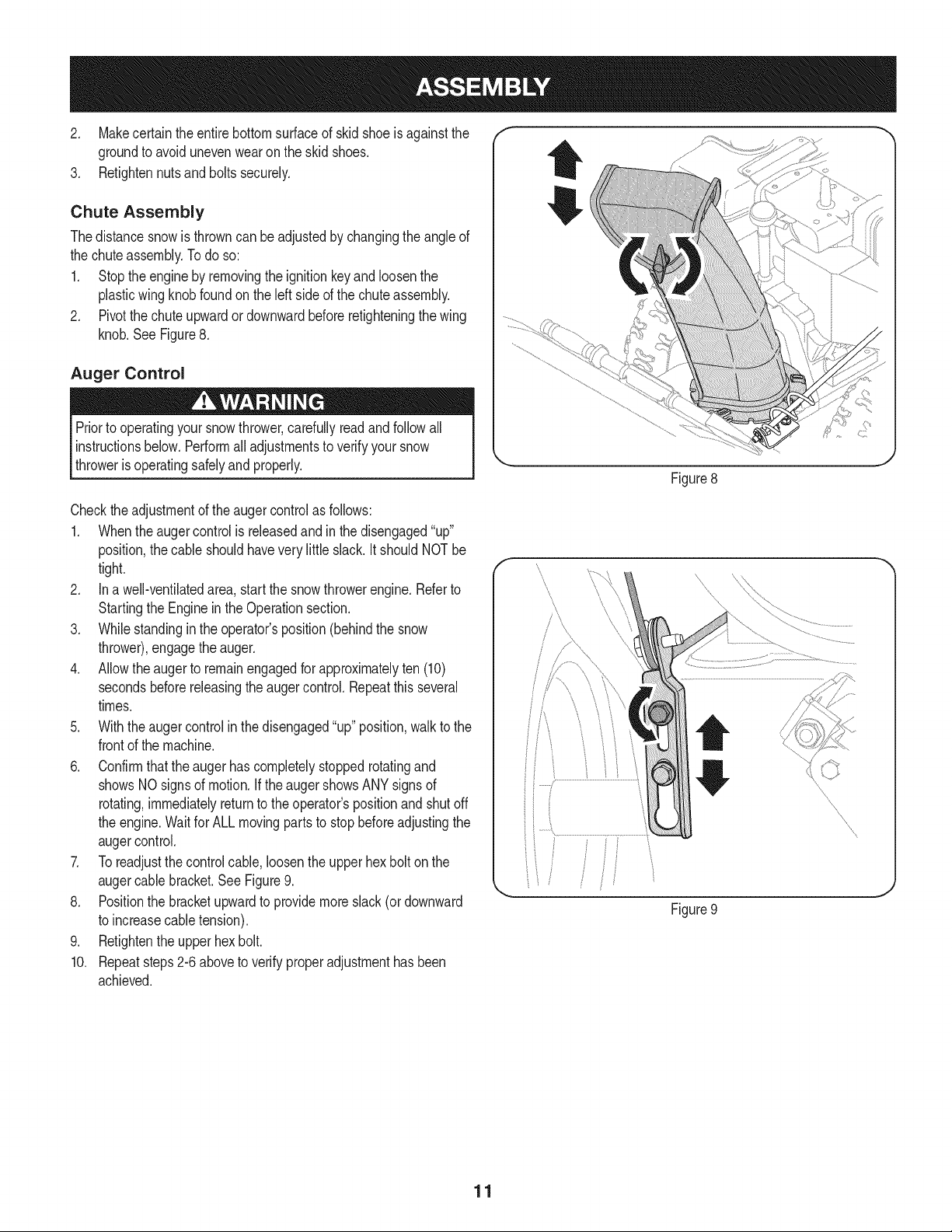
Skid Shoes
The snowthrowerskid shoesare adjustedupwardat thefactory for
shippingpurposes.Adjustthemdownward,if desired,priorto operat-
ingthe snowthrower.
It is not recommendedthatyouoperatethis snowthrowerongravel
as it can easilypickup andthrowloosegravel,causingpersonal
njuryordamageto the snowthrowerand surroundng property.
• Forclosesnowremovalona smoothsurface,raiseskidshoes
higheronthe augerhousing.
• Usea middleor lowerpositionwhentheareato be clearedis
uneven,such as a graveldriveway
ChuteClean-outTool
Figure6
f
Figure7
NOTE:If youchooseto operatethe snowthroweron a gravelsurface,
keepthe skid shoesin positionfor maximumclearancebetweenthe
groundandthe shaveplate.
Toadjustthe skidshoes:
1. Loosenthe four hexnuts (two on each side)andcarriagebolts.
Moveskidshoesto desiredposition. SeeFigure7.
10
2, Makecertain theentirebottomsurfaceof skidshoeis againstthe f
groundto avoidunevenwearon the skidshoes, ....
3, Refightennutsandboltssecurely,
Chute Assembly
Thedistancesnowis throwncan be adjustedby changingthe angleof
the chuteassembly,Todo so:
1, Stopthe engineby removingthe ignitionkeyandloosenthe
plasticwingknobfoundonthe left sideof the chuteassembly.
2, Pivotthe chuteupwardor downwardbeforeretighteningthewing
knob,See Figure8,
Auger Control
Priorto operatingyoursnowthrower,carefullyreadand follow all
instructionsbelow,Performall adjustmentsto verifyyour snow
throweris operatingsafelyand properly,
Figure8
Checktheadjustmentof the augercontrolas follows:
1. Whentheaugercontrolis releasedandin the disengaged"up"
position,the cableshouldhavevery littleslack.ItshouldNOTbe
tight.
2. In a well-ventilatedarea,start the snowthrowerengine.Referto
Startingthe Engineinthe Operationsection.
3. Whilestandingin the operator'sposition(behindthe snow
thrower),engagethe auger.
4. Allowtheauger to remainengagedfor approximatelyten (10)
secondsbeforereleasingthe augercontrol.Repeatthisseveral
times.
5. With theauger controlin thedisengaged"up" position,walkto the
frontof the machine.
6. Confirmthatthe augerhas completelystoppedrotatingand
showsNOsignsof motion.If the augershowsANYsignsof
rotating,immediatelyreturnto the operator'spositionand shutoff
the engine.Waitfor ALLmovingpartsto stop beforeadjustingthe
augercontrol.
7. Toreadjustthecontrolcable, loosentheupperhexbolt on the
augercablebracket.SeeFigure9.
8. Positionthe bracketupwardto providemoreslack(or downward
to increasecabletension).
9. Retightenthe upperhex bolt.
10. Repeatsteps2-6 aboveto verifyproperadjustmenthasbeen
achieved.
11
f
Drive Control
Shift Lever
J
J
Auger Control
Gas Cap
ChuteAssembly OilFill
\ \,
\
\
j_. ChuteDirectionalControl
Clean Out
Tool
\
Augers
Skid Shoe
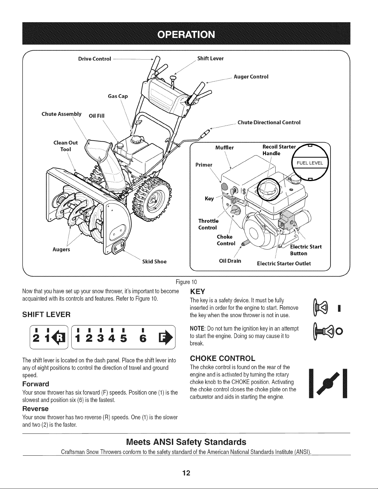
Nowthat youhavesetup yoursnowthrower,it'simportantto become
acquaintedwith itscontrolsand features.Referto Figure10.
SHIFT LEVER
Primer
Mumer Recoil Starter
_.Handle
Key
Throttle
Control
Choke
Control
Oil Drain
:lectric Start
Button
Electric Starter Outlet
,.. j
Figure10
KEY
The key is a safetydevice.It mustbe fully
insertedin orderfor the engineto start. Remove
the key whenthe snowthroweris not in use.
'
1 2345 6
NOTE: Donot turnthe ignitionkeyinan attempt
to startthe engine.Doingso maycauseit to
break.
J
The shiftleveris locatedonthe dash panel.Placethe shift leverinto
anyof eight positionsto controlthe directionof travel and ground
speed.
Forward
Yoursnowthrowerhas six forward(F) speeds.Positionone (1)is the
slowestandpositionsix(6) is the fastest.
Reverse
Yoursnowthrowerhastwo reverse(R) speeds.One (1) is the slower
andtwo(2) is the faster.
CHOKE CONTROL
The chokecontrolis foundon the rearof the
engineand is activatedby turningthe rotary
chokeknobto the CHOKEposition.Activating
the chokecontrolclosesthe choke plateon the
carburetorandaids in startingthe engine.
Meets ANSI Safety Standards
CraftsmanSnowThrowersconformto the safetystandardof the AmericanNationalStandardsInstitute(ANSI).
12
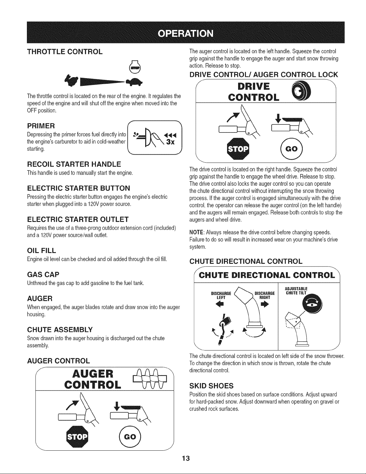
THROTTLE CONTROL
aiW'
Thethrottlecontrolis locatedon the rearof the engine.It regulatesthe
speedof theengineandwill shutoff the enginewhenmovedintothe
OFFposition.
r 1
Depressingthe primerforcesfuel directlyinto ___144
the engine'scarburet°rt° aid inc°'dweather k _"_'-_ 3" Jstarting.
RECOIL STARTER HANDLE
Thishandleis usedto manuallystartthe engine.
ELECTRIC STARTER BUTTON
Pressingthe electricstarterbuttonengagesthe engine'selectric
starterwhenpluggedintoa 120Vpowersource.
ELECTRIC STARTER OUTLET
Requiresthe useof athree-prongoutdoorextensioncord(included)
anda 120Vpowersource/walloutlet.
OIL FILL
Engineoil levelcan be checkedand oiladdedthroughtheoil fill.
GAS CAP
Unthreadthe gascap to addgasolineto the fuel tank.
AUGER
Whenengaged,the augerbladesrotateand drawsnowintothe auger
housing.
CHUTE ASSEMBLY
Snowdrawninto theaugerhousingis dischargedout the chute
assembly.
AUGER CONTROL
The augercontrolis locatedon the left handle.Squeezethe control
gripagainstthe handleto engagethe augerand startsnowthrowing
action.Releaseto stop.
DRIVE CONTROL/AUGER CONTROL LOCK
J DRIVE
CONTROL
The drivecontrolis locatedon the righthandle.Squeezethe control
gripagainstthe handleto engagethe wheeldrive.Releaseto stop.
The drivecontrolalso lockstheaugercontrolso youcan operate
the chute directionalcontrolwithoutinterruptingthe snowthrowing
process.If the augercontrolis engagedsimultaneouslywith the drive
control,the operatorcan releasethe augercontrol(onthe lefthandle)
andthe augerswill remainengaged.Releaseboth controlsto stopthe
augersandwheeldrive.
NOTE:Alwaysreleasethedrivecontrolbeforechangingspeeds.
Failureto do so will result in increasedwearon yourmachine'sdrive
system.
CHUTE DIRECTIONAL CONTROL
/_CCHUTE DIRECTIONAL CONTROL
ADJUSTABLE
DISCHARGE CHUTETILTDISCHARGE
LEFT
#
_ J
The chute directional control is located on left side of the snow thrower.
Tochange the direction inwhich snow is thrown, rotate the chute
directional control.
SKID SHOES
Positionthe skid shoesbasedonsurfaceconditions.Adjustupward
for hard-packedsnow.Adjustdownwardwhenoperatingon gravelor
crushedrocksurfaces.
13
CLEAN-OUT TOOL
Neveruse yourhandsto cleara cloggedchute assembly.Shut
off engineandremainbehindhandlesuntilall movingpartshave
stoppedbeforeusingthe clean-outtoolto clear thechute assembly.
Thechuteclean-outtool is convenientlyfastenedto the rearof the
augerhousingwith a mountingclip. Shouldsnowandice become
lodgedin thechuteassemblyduringoperation,proceedas followsto
safelycleanthechuteassemblyand chute opening:
1. Releaseboththe AugerControlandthe DriveControl.
2. Stopthe engineby removingthe ignitionkey.
3. Removethe clean-outtoolfromthe clip whichsecuresit to the
rearof the augerhousing.
4. Use the shovel-shapedend of theclean-outtool to dislodgeand
scoopany snowand icewhichhasformedin andnearthechute
assembly.
5. Refastenthe clean-outtool to the mountingclip on the rearof
theaugerhousing,reinsertthe ignitionkeyandstartthe snow
thrower'sengine.
6. Whilestandingin the operator'sposition(behindthesnow
thrower),engagethe augercontrolfora fewsecondsto clear any
remainingsnowand ice fromthechuteassembly.
BEFORE STARTING ENGINE
Read,understand,and followall instructionsand warningson the
machineand inthismanualbeforeoperating.
Oil
Theunit wasshippedwith oil in the engine.Checkoil levelbefore
eachoperationto ensureadequateoil inthe engine.Forfurther
instructions,refertothe stepson page16.
NOTE:Besureto checkthe engineon a levelsurfacewiththe engine
stopped.
1. Removethe oil fillercap/dipstickandwipethe dipstickclean.
2. insertthe cap/dipstickintothe oilfiller neck,butdo NOTscrewit
in.
3. Removethe oil fillercap/dipstick,ifthe levelislow,slowlyadd
oil (5%30, witha minimumclassificationof SF/SG)untiloil level
registersbetweenhigh (H) and low(L).
NOTE:Do notoverfill.Overfillingwithoil mayresultinenginesmoking,
hardstartingor sparkplugfouling.
4. Replaceand tighten cap/dipstickfirmlybeforestartingengine.
Gasoline
Useautomotivegasoline(unleadedor low leadedto minimizecombus-
tionchamberdeposits)with a minimumof 87octane.Gasolinewith
upto 10%ethanolor 15%MTBE(MethylTertiaryButylEther)canbe
used.Neveruseanoil/gasolinemixtureor dirtygasoline.Avoidgetting
dirt,dust,or waterinthefuel tank. DO NOTuse E85gasoline.
• Refuelin a well-ventilatedareawiththe enginestopped.Do not
smokeorallowflamesor sparksin the areawherethe engineis
refueledor wheregasolineisstored.
• Donot overfillthe fueltank.After refueling,makesurethe tank
cap is closedproperlyand securely.
• Be carefulnotto spillfuel whenrefueling.Spilledfuel orfuel vapor
mayignite,ifany fuelis spilled,makesurethe area isdry before
startingthe engine.
• Avoidrepeatedor prolongedcontact with skinor breathingof
)or.
Useextremecarewhen handlinggasoline.Gasolineis extremely
flammableand thevaporsare explosive.Never fuelthe machine
indoorsorwhilethe engine ishotor running.Extinguishcigarettes,
cigars,pipesandothersourcesof ignition.
1. Cleanaroundfuel fill beforeremovingcap to fuel.
2. A fuel levelindicatorislocatedinthe fueltank. See Figure10
inset.Be carefulnotto overfill.Filltank untilfuel reachesthe fuel
levelindicatorto allowspacefor fuel expansion.
STARTING THE ENGINE
Alwayskeep handsand feet clearof movingparts. Donot usea
pressurizedstartingfluid.Vaporsare flammable.
NOTE:Allowthe engineto warm up for a fewminutesafter starting.
The enginewill notdevelopfull poweruntilit reachesoperating
temperatures.
1. Makecertainboththe augercontrolanddrivecontrolarein the
disengaged(released)position.
2. insertkeyinto slot. Makesureit snapsintoplace.Donot attempt
to turn the key.
NOTE: Theenginecannotstartwithoutthe keyfully insertedintothe
ignitionswitch.
Electric Starter
The optionalelectricstarteris equippedwitha groundedthree-wire
powercordand plug,andis designedto operateon 120voltAC
householdcurrent.Itmustbe usedwitha properlygroundedthree-
prongreceptacleat all timesto avoidthe possibilityof electricshock.
Followall instructionscarefullyprior to operatingthe electricstarter.
DONOTuseelectricstarterinthe rain.
Determinethat yourhome'swiringis a three-wiregroundedsystem.
Aska licensedelectricianif you arenotcertain.
Ifyou havea groundedthree-prongreceptacle,proceedas follows.
Ifyou do not havethe properhousewiring, DONOT usethe electric
starterunderanyconditions.
1. Plugthe extensioncord intothe outletlocatedon the engine's
surface.Plugthe otherendof extensioncord intoa three-prong
120-volt,grounded,AC outletina well-ventilatedarea.
14
2. Movethrottlecontrolto FAST(rabbit)_T position.
3. Movechoketo the CHOKE IJl position(coldenginestart).If
engineis warm,placechokein RUNposition.
4. Pushprimerthree (3) times, makingsureto coverventholein
primerbulbwhen pushing.If engineis warm,pushprimeronly
once.Alwayscover venthole whenpushing.Coolweathermay
requireprimingto be repeated.
5. Pushstarterbuttonto start engine.Oncethe enginestarts,im-
mediatelyreleasestarterbutton.Electricstarteris equippedwith
thermaloverloadprotection;systemwill temporarilyshut-downto
allowstarterto cool if electricstarterbecomesoverloaded.
6. As theenginewarms,slowlyrotatethe chokecontrolto RUN
position.If the enginefalters,restartengineandrunwithchoke
at half-chokepositionfor a shortperiodof time,andthen slowly
rotatethe chokeinto RUNposition.
7. After engineis running,disconnectpowercordfrom electric
starter.Whendisconnecting,alwaysunplugthe endat the wall
outletbeforeunpluggingtheoppositeend from the engine.
Recoil Starter
Do notpull the starterhandlewhilethe enginerunning.
1. Movethrottlecontrolto FAST(rabbit)_J_ position.
2. Movechoketo the CHOKE I,'_¢1position(coldenginestart).If
engineis warm,placechokein RUNposition.
3. Pushprimerthree (3) times, makingsureto coverventholewhen
pushing.Ifengineiswarm,push primeronlyonce.Alwayscover
ventholewhen pushing.Coolweathermayrequireprimingto be
repeated.
4. Pull gentlyon the starterhandleuntil it beginsto resist,then
pullquicklyandforcefullyto overcomethe compression.Do
not releasethe handleandallowit to snapback.Returnrope
SLOWLYto originalposition.If required,repeatthisstep.
5. As theenginewarms,slowlyrotatethe chokecontrolto RUN
position.If the enginefalters,restartengineandrunwithchoke
at half-chokepositionfor a shortperiodof time,andthen slowly
rotatethe chokeinto RUNposition.
Toavoid unsupervisedengineoperation,neverleavethemachine
unattendedwith the enginerunning.Turnthe engineoffafteruseand
removekey.
STOPPING THE ENGINE
Afteryouhavefinishedsnow-throwing,run enginefora few minutes
beforestoppingto helpdry off any moistureon the engine.
1. Movethrottlecontrolto OFFposition.
2. Removethekey.Removingthe keywill reducethe possibilityof
unauthorizedstartingof the enginewhileequipmentis notin use.
Keepthe keyin a safeplace.The enginecannotstart withoutthe
key.
3. Wipeany moistureawayfrom the controlson theengine.
TO ENGAGE DRIVE
1. Withthe throttlecontrolinthe Fast(rabbit) '_ position,move
shiftleverintooneof thesix forward(F) positionsortwo reverse
(R) positions.Selecta speedappropriatefor the snowconditions
anda paceyou'recomfortablewith.
NOTE: When selectinga DriveSpeed,use the slowerspeedsuntil
you are comfortableand familiarwiththe operationof the snow
thrower.
2. Squeezethe drivecontrolagainstthe handleand the snow
throwerwill move.Releaseit anddrive motionwill stop.
NOTE:NEVERrepositionthe shiftlever(changespeedsordirection
of travel)withoutfirst releasingthe drivecontrolandbringingthe snow
throwerto a completestop.Doingsowill resultin prematurewearto
the snow thrower'sdrivesystem.
TO ENGAGE AUGER
1. Toengagethe augerand startthrowingsnow,squeezethe auger
controlagainstthe left handle.Releaseto stopthe auger.
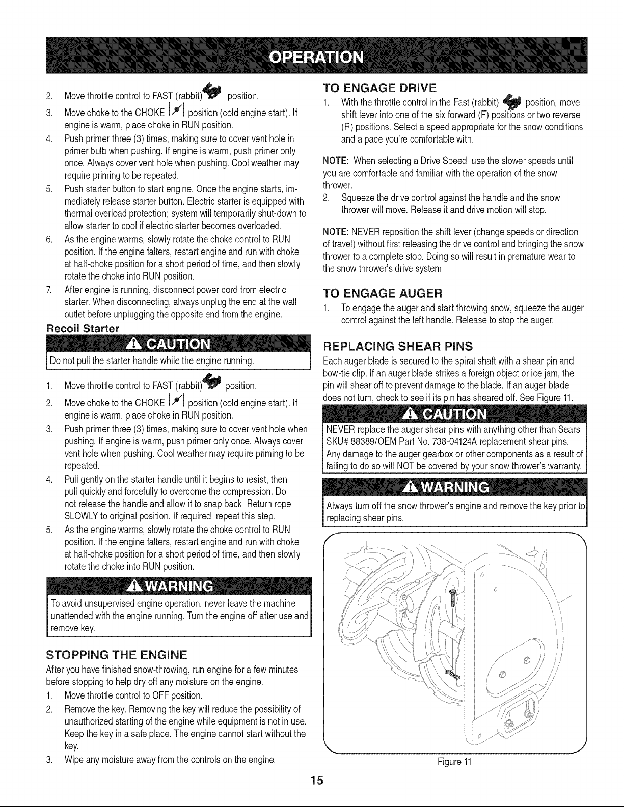
REPLACING SHEAR PINS
Eachauger blade is securedto the spiralshaftwith a shearpinand
bow-tieclip. Ifanaugerbladestrikesa foreignobjector icejam,the
pinwillshearoff to preventdamageto the blade.If an auger blade
does notturn,checkto see if its pinhas shearedoff. See Figure11.
NEVERreplacethe augershearpinswithanythingotherthanSears
SKU#88389/0EMPart No.738-04124Areplacementshearpins.
Anydamageto the augergearboxor othercomponentsas a resultof
[fang to doso w NOTbe coveredby yoursnowthrowers warranty.
Alwaysturnoff the snowthrower'sengineandremovethe keypriorto
replacingshearpins.
s ¸......
iJ
Figure11
15
MAINTENANCE SCHEDULE
Beforeperforminganytypeofmaintenance/service,disengageall
controlsand stoptheengine.Waituntilallmovingpartshavecometo
acompletestop.Disconnectsparkplugwireandgroundit againstthe
enginetopreventunintendedstarting.Alwayswearsafetyglassesduring
operationor whileperforminganyadjustmentsor repairs.
EachUseandevery5
hours
1st5 hours
Annuallyor 25 hours
Annuallyor 50 hours
Annuallyor 100hours
BeforeStorage
1. Engineoil level
2. Looseor missinghardware
3. Unitand engine.
1. Engineoil
1. Sparkplug
2. Controllinkagesand pivots
3. Wheels
4. Gear shaftand Augershaft
1. Engineoil
1. Sparkplug
1. Fuelsystem
Followthe maintenanceschedulegiven below.This chart describes
serviceguidelinesonly.Usethe ServiceLogcolumnto keeptrackof
completedmaintenancetasks.To locate the nearest Sears Service
Centeror to scheduleservice,simplycontactSearsat
1-800-4-MY-HOME®.
1. Check
2. Tightenor replace
3. Clean
1. Change
1. Check
2. Lubewith light oil
3. Lubewith multipurposeautogrease
4. Lubewith light oil
1. Change
1. Change
1. Runengineuntilit stopsfrom lack
offuel
ENGINE MAINTENANCE
Checking Engine Oil
Beforelubricating,repairing,or inspecting,disengageall controls
Iandstopengine.Wait untilall movingpartshavecometo a complete
_stop.
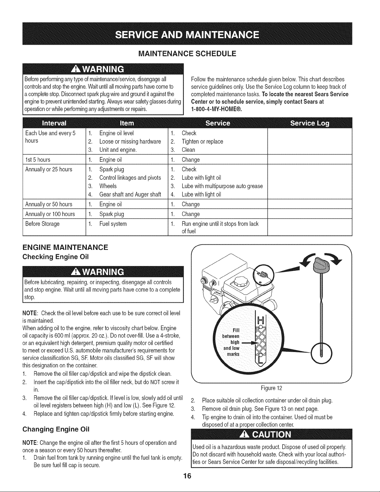
NOTE: Checktheoil levelbeforeeachuseto besurecorrectoil level
is maintained.
Whenaddingoilto the engine,referto viscositychart below.Engine
oilcapacityis 600ml (approx.20 oz.). Donot over-fill.Usea 4-stroke,
oran equivalenthighdetergent,premiumquality motoroil certified
to meet or exceedU.S.automobilemanufacturer'srequirementsfor
serviceclassificationSG, SR MotoroilsclassifiedSG, SFwill show
thisdesignationon the container.
1. Removethe oil fillercap/dipstickandwipethe dipstickclean.
2. Insertthe cap/dipstickintothe oilfiller neck,butdo NOTscrewit
in.
3. Removethe oil fillercap/dipstick.Iflevelis low,slowlyadd oiluntil
oil levelregistersbetweenhigh(H) and low (L). See Figure12.
4. Replaceand tighten cap/dipstickfirmlybeforestartingengine.
Changing Engine Oil
NOTE:Changethe engineoilafterthe first5 hoursof operationand
oncea seasonorevery50 hoursthereafter.
1. Drainfuelfrom tank by runningengineuntilthe fuel tank is empty.
Besurefuel fill cap is secure.
f
1 •
_i!_!iiii_ii!i!jili iiiI iiiii_H
marks
Figure12
2. Placesuitableoil collectioncontainerunderoil drainplug.
3. Removeoil drainplug.SeeFigure13on nextpage.
4. Tip engineto drain oil intothe container.Usedoil mustbe
disposedof at a propercollectioncenter.
Usedoil isa hazardouswasteproduct.Disposeof usedoil properly.
IDo notdiscardwithhouseholdwaste.Checkwithyour localauthori-
lties or SearsServiceCenterfor safe disposal/recyclingfacilities.
16
.
6.
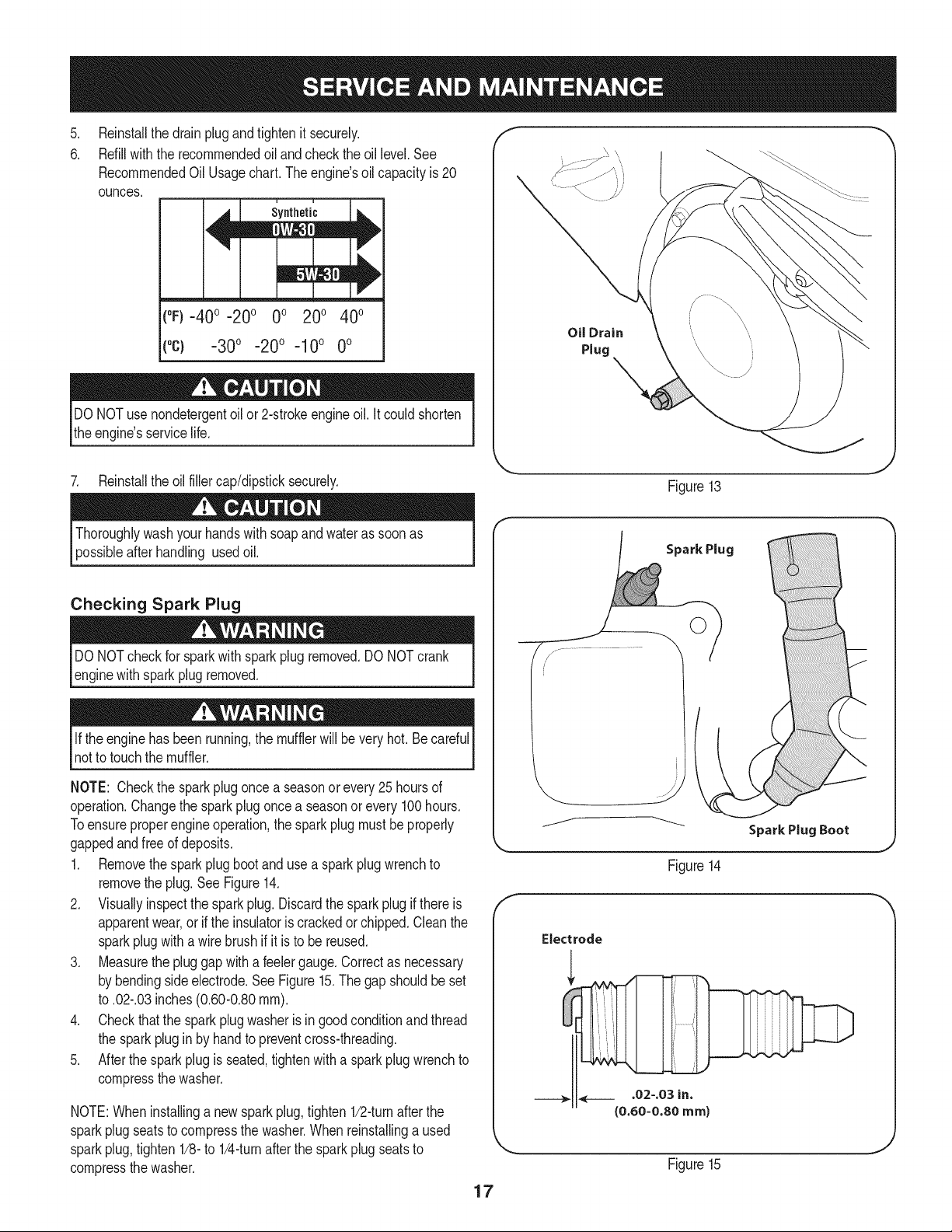
Reinstallthe drainplugandtightenit securely.
Refillwiththe recommendedoil and checkthe oil level.See
RecommendedOil Usagechart.Theengine'soil capacityis 20
ounces.
(%-400 -200 0o 200 400
("c) -300 -200 -10° 0°
DONOTuse nondetergentoil or 2-strokeengineoil. Itcould shorten
the engine'sservicelife.
7. Reinstallthe oil fillercap/dipsticksecurely.
Oil Drain
Plug
Figure13
afterhandling usedoil.
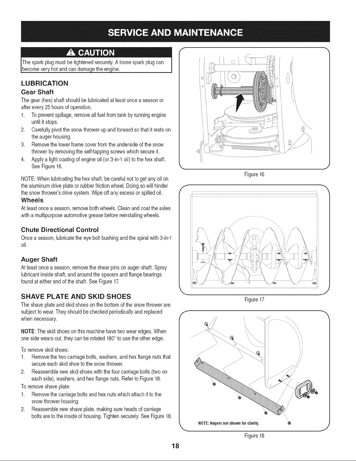
Checking Spark Plug
DO NOTcheckfor sparkwithsparkplugremoved.DO NOTcrank
enginewithsparkplugremoved.
Ifthe engine hasbeenrunning,the mufflerwill bevery hot.Becareful
notto touchthe muffler.
NOTE: Checkthe sparkplugoncea seasonorevery25hoursof
operation.Changethe sparkplug oncea seasonor every100hours.
Toensureproperengine operation,the sparkplugmustbe properly
gappedandfreeof deposits.
1. Removethesparkplugbootanduse a sparkplugwrenchto
removethe plug.See Figure14.
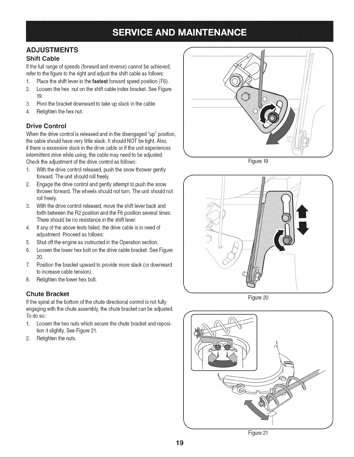
2. Visuallyinspectthe spark plug.Discardthe sparkplugif thereis
apparentwear,or if the insulatoris crackedor chipped.Cleanthe
sparkplugwitha wirebrush if it is to be reused.
3. Measurethe pluggapwitha feelergauge.Correctas necessary
by bendingsideelectrode.See Figure15.The gap shouldbe set
to .02-.03inches(0.60-0.80ram).
4. Checkthatthe sparkplug washeris ingoodconditionandthread
the sparkplug in by handto preventcross-threading.
5. After thespark plug is seated,tightenwith a sparkplugwrenchto
compressthe washer.
NOTE:Wheninstallinga newsparkplug,tighten1/2-turnafter the
sparkplugseatsto compressthe washer.Whenreinstallinga used
sparkplug,tighten1/8-to 1/4-turnafter the sparkplugseatsto
compressthe washer.
17
Spark Plug
O
J
Figure14
Electrode
.02-.03 in.
{0.60-0.80 ram)
Figure15
become hotandcan inc.
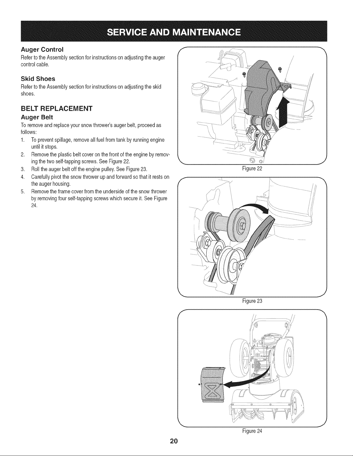
LUBRICATION
Gear Shaft
Thegear(hex)shaft shouldbe lubricatedat least oncea seasonor
afterevery25 hoursof operation.
1. Topreventspillage,removeall fuel fromtank by runningengine
until it stops.
2. Carefullypivotthe snowthrowerupandforwardso that it restson
theaugerhousing.
3. Removethe lowerframecoverfromthe undersideof the snow
throwerby removingthe self-tappingscrewswhich secureit.
4. Applya lightcoatingof engineoil (or3-in-1oil) to the hexshaft.
SeeFigure16.
NOTE:Whenlubricatingthe hexshaft,be carefulnotto get any oil on
thealuminumdriveplateor rubberfrictionwheel.Doingsowill hinder
the snowthrower'sdrive system.Wipeoff anyexcessor spilledoil.
Wheels
At least oncea season,removebothwheels.Cleanandcoattheaxles
witha multipurposeautomotivegreasebeforereinstallingwheels.
Chute Directional Control
Oncea season,lubricatethe eye boltbushingand thespiralwith3-in-1
oil.
Auger Shaft
At least oncea season,removethe shearpinson augershaft.Spray
lubricantinsideshaft,andaroundthe spacersand flangebearings
foundat eitherendof the shaft.SeeFigure17.
f
Figure16
SHAVE PLATE AND SKID SHOES
The shaveplateand skidshoesonthe bottomof the snowthrowerare
subjectto wear.Theyshouldbecheckedperiodicallyandreplaced
whennecessary.
NOTE:Theskidshoeson thismachinehavetwowearedges.When
onesidewearsout,theycan be rotated1800to usethe otheredge.
To removeskid shoes:
1. Removethe twocarriagebolts,washers,andhex flangenutsthat
secureeachskidshoeto the snow thrower.
2. Reassemblenew skidshoeswiththe fourcarriagebolts(twoon
eachside),washers,and hex flangenuts.Referto Figure18.
To removeshaveplate:
1. Removethe carriageboltsand hexnutswhichattachit to the
snowthrowerhousing.
2. Reassemblenew shaveplate,makingsureheadsof carriage
boltsareto the insideof housing.Tightensecurely.SeeFigure18.
Figure17
NOTE:Augers not shown for clarity.
Figure18
/
/
/
/
18
ADJUSTMENTS
Shift Cable
If thefull rangeof speeds(forwardandreverse)cannotbe achieved,
referto the figureto the rightand adjustthe shift cableas follows:
1. Placethe shiftleverin thefastest forwardspeedposition(F6).
2. Loosenthe hex nuton the shiftcable indexbracket.SeeFigure
19.
3. Pivotthe bracketdownwardto takeupslack in the cable.
4. Retightenthehex nut.
Drive Control
Whenthedrivecontrolis releasedandin thedisengaged"up"position,
the cableshouldhavevery little slack.It shouldNOTbetight. Also,
if thereis excessiveslackin thedrive cableor if the unitexperiences
intermittentdrivewhileusing,the cable mayneedto be adjusted.
Checktheadjustmentof the drivecontrolas follows:
1. Withthedrivecontrolreleased,pushthe snowthrowergently
forward.The unitshouldrollfreely.
2. Engagethe drivecontrolandgentlyattemptto pushthe snow
throwerforward.Thewheelsshouldnotturn.The unitshouldnot
rollfreely.
3. With thedrivecontrol released,movethe shift leverbackand
forthbetweenthe R2positionand the F6 positionseveraltimes.
Thereshouldbeno resistancein the shiftlever.
4. If anyof the abovetests failed,the drivecable is in needof
adjustment.Proceedas follows:
5. Shutoff theengineas instructedin the Operationsection.
6. Loosenthe lowerhexbolt on the drivecable bracket.See Figure
20.
7. Positionthe bracketupwardto providemoreslack(or downward
to increasecabletension).
8. Retightenthe lowerhex bolt.
Figure19
f
Chute Bracket
If the spiralat the bottomof the chutedirectionalcontrolis notfully
engagingwith the chuteassembly,the chutebracketcan beadjusted.
Todo so:
1. Loosenthe two nuts whichsecurethechutebracketandreposi-
tion it slightly.See Figure21.
2. Retightenthe nuts.
f
Figure20
Figure21
19
Auger Control f "_
Referto the Assemblysectionfor instructionson adjustingtheauger
controlcable.
Skid Shoes
Referto the Assemblysectionfor instructionson adjustingthe skid
shoes.
BELT REPLACEMENT
Auger Belt
To removeand replaceyoursnowthrower'saugerbelt,proceedas
follows:
1. Topreventspillage,removeall fuel fromtank by runningengine
until itstops.
2. Removethe plasticbelt coveron the frontof the engineby remov-
ingthe two self-tappingscrews.SeeFigure22.
3. Rollthe augerbeltoff theenginepulley.See Figure23.
4. Carefullypivotthe snowthrowerupandforwardso that itrestson
theaugerhousing.
5. Removethe framecoverfromthe undersideof the snow thrower
by removingfourself-tappingscrewswhichsecureit.SeeFigure
24.
f
Figure22
J
f
Figure 23
//
2O
Figure24
J
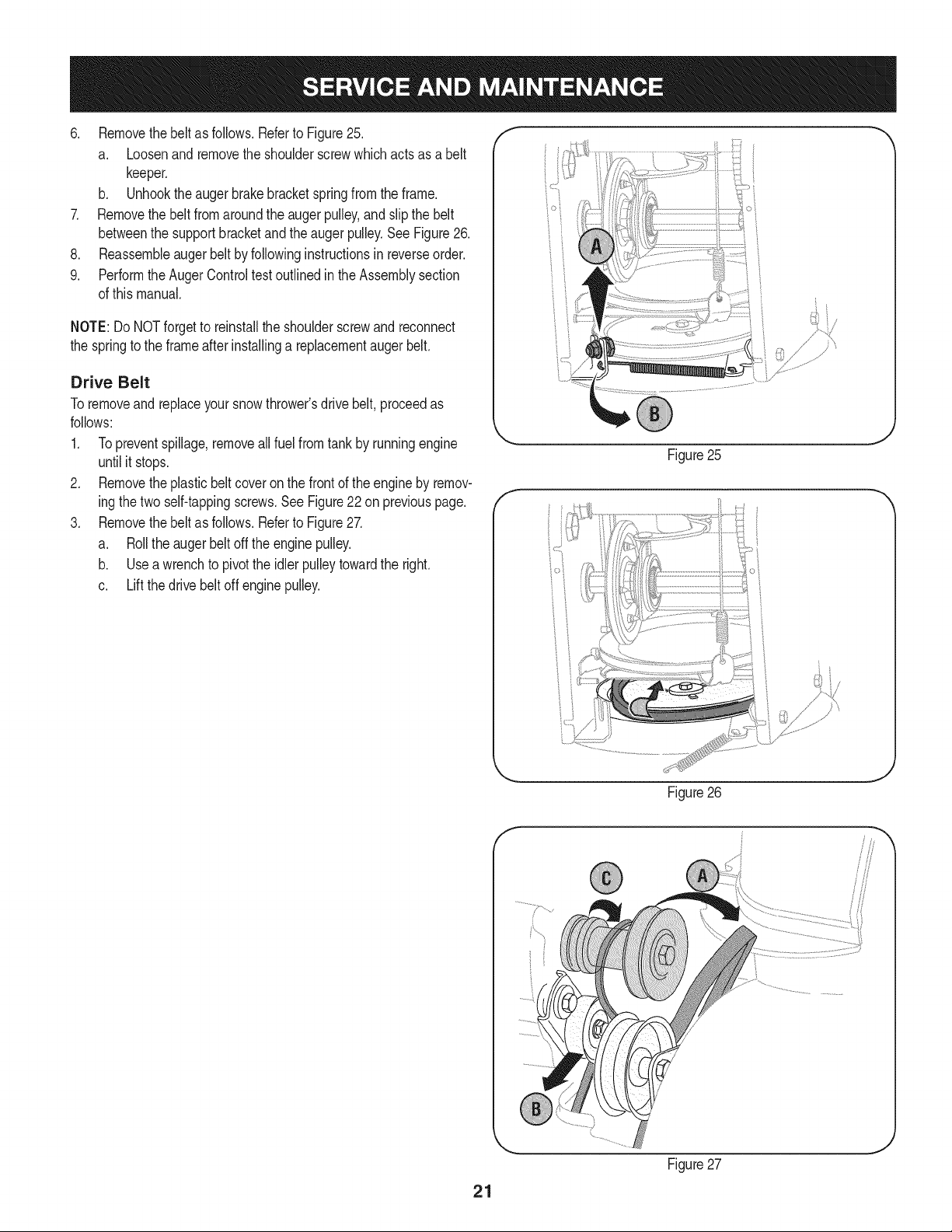
6. Removethebeltasfollows.RefertoFigure25.
a. Loosenandremovetheshoulderscrewwhichactsasabelt
keeper.
b. Unhooktheaugerbrakebracketspringfromtheframe.
7. Removethebeltfromaroundtheaugerpulley,andslipthebelt
betweenthesupportbracketandtheaugerpulley.SeeFigure26.
8. Reassembleaugerbeltbyfollowinginstructionsinreverseorder.
9. PerformtheAugerControltestoutlinedintheAssemblysection
ofthismanual.
NOTE:DoNOTforgettoreinstalltheshoulderscrewandreconnect
thespringtotheframeafterinstallingareplacementaugerbelt.
Drive Belt
Toremoveand replaceyoursnowthrower'sdrivebelt,proceedas
follows:
1. Topreventspillage,removeall fuel fromtankby runningengine
untilit stops.
2. Removetheplasticbelt coveronthe front of the engineby remov-
ingthe two self-tappingscrews.See Figure22on previouspage.
3. Removethebelt as follows.Referto Figure27.
a. Rollthe augerbeltoff theenginepulley.
b. Use a wrenchto pivotthe idlerpulleytowardthe right.
c. Liftthe drivebelt off enginepulley.
Figure25
Figure26
21
Figure27
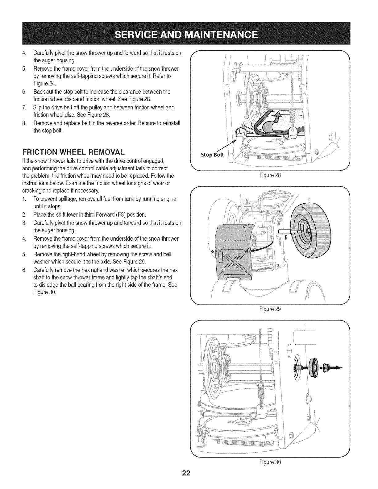
4, Carefullypivotthesnowthrowerupandforwardsothatitrestson
theaugerhousing.
5. Removetheframecoverfromtheundersideofthesnowthrower
byremovingtheself-tappingscrewswhichsecureit.Referto
Figure24,
6. Backoutthestopbolttoincreasetheclearancebetweenthe
frictionwheeldiscandfrictionwheel,SeeFigure28,
7. Slipthedrivebeltoffthepulleyandbetweenfrictionwheeland
frictionwheeldisc,SeeFigure28,
8, Removeandreplacebeltinthereverseorder,Besuretoreinstall
thestopbolt.
FRiCTiON WHEEL REMOVAL
Ifthe snowthrowerfailsto drive withthedrivecontrolengaged,
andperformingthe drivecontrolcableadjustmentfailsto correct
the problem,the frictionwheelmayneedto be replaced.Followthe
instructionsbelow.Examinethe frictionwheelfor signsof wearor
crackingand replaceif necessary.
1. Topreventspillage,removeall fuel fromtank by runningengine
until it stops.
2. Placethe shiftleverin third Forward(F3) position.
3. Carefullypivotthe snowthrowerupandforwardso that it restson
theaugerhousing.
4. Removethe framecoverfromthe undersideof the snow thrower
by removingthe self-tappingscrewswhich secureit.
5. Removethe right-handwheelby removingthe screwand bell
washerwhichsecureit to theaxle.See Figure29.
6. Carefullyremovethe hexnut andwasherwhichsecuresthe hex
shaftto the snowthrowerframeand lightlytap the shaft'send
to dislodgethe ballbearingfromthe rightsideof theframe.See
Figure30.
Stop Bolt
Figure28
/ ii
Figure29
J
Figure30
J
22
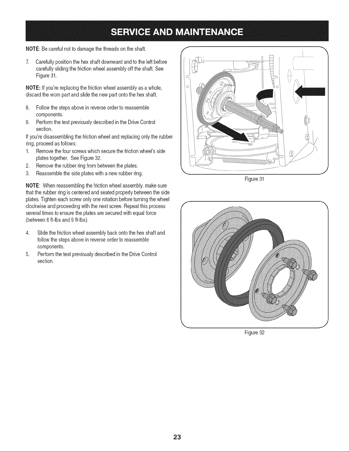
NOTE:Becarefulnot to damagethe threadson the shaft,
7. Carefullypositionthe hexshaftdownwardand to the left before
carefullyslidingthe frictionwheelassemblyoff the shaft.See
Figure31.
NOTE: If you'rereplacingthe frictionwheelassemblyas a whole,
discardthe wornpartand slidethe newpart ontothe hexshaft.
8. Followthe stepsabovein reverseorderto reassemble
components.
9. Performthetest previouslydescribedin the DriveControl
section.
If you'redisassemblingthefrictionwheeland replacingonly the rubber
ring,proceedas follows:
1. Removethefour screwswhichsecurethe frictionwheel'sside
platestogether. SeeFigure32.
2. Removethe rubberring from betweenthe plates.
3. Reassemblethe side plateswith a newrubberring.
NOTE: Whenreassemblingthe frictionwheelassembly,makesure
thatthe rubberring is centeredand seatedproperlybetweenthe side
plates.Tighteneachscrewonlyone rotationbeforeturningthe wheel
clockwiseand proceedingwiththe nextscrew.Repeatthisprocess
severaltimes toensurethe platesare securedwith equalforce
(between6 ft-lbsand 9 ft-lbs).
Figure31
4. Slidethe frictionwheelassemblybackonto the hexshaftand
followthestepsabovein reverseorderto reassemble
components.
5. Performthe testpreviouslydescribedin the DriveControl
section.
t j
Figure32
23
Ifthe snowthrowerwillnot be usedfor30 daysor longer,or if it is the end of the snowseasonwhenthe lastpossibilityof snowis gone,the
equipmentneedsto bestoredproperly.Followstorageinstructionsbelowto ensuretop performancefrom the snowthrowerfor manymoreyears.
PREPARING ENGINE
Enginesstoredover30 days need to bedrainedof fuel to prevent
deteriorationandgumfromforminginfuel systemor onessential
carburetorparts.If thegasolineinyourenginedeterioratesduring
storage,youmay needto havethe carburetor,and otherfuel system
components,servicedor replaced.
1. Removeall fuel fromtank by runningengineuntil it stops.Donot
attemptto pourfuel from the engine.
2. Changethe engineoil.
3. Removesparkplugandpourapproximately1oz.(30 rnl)of clean
engineoil intothe cylinder.Pullthe recoilstarterseveraltimesto
distributetheoil, and reinstallthe spark plug.
4. Cleandebrisfromaroundengine,andunder,around,andbehind
muffler.Applya lightfilmof oil on anyareasthatare susceptible
to rust.
• Storeina clean,dry andwellventilatedareaawayfromanyap-
pliancethat operateswith a flame or pilotlight,suchas a furnace,
waterheater,or clothesdryer.Avoidany areawitha spark
producingelectricmotor,or wherepowertoolsareoperated.
Neverstoresnowthrowerwithfuel in tank indoorsor inpoorlyventi-
latedareas,wherefuel fumesmayreachan openflame,sparkor pilol
lightas on a furnace,water heater,clothesdryer orgas appliance.
• If possible,avoidstorageareaswithhighhumidity.
• Keepthe enginelevelin storage.Tiltingcan causefuel oroil
leakage.
PREPARING SNOW THROWER
Whenstoringthe snowthrowerin anunventilatedormetal stor-
age shed,careshouldbetakento rustprooftheequipment.Using
a light oilor silicone,coattheequipment,especiallyanychains,
springs,bearingsand cables.
• Removealldirt fromexteriorof engineandequipment.
• Followlubricationrecommendations.
• Storeequipmentin a clean,dry area.
24
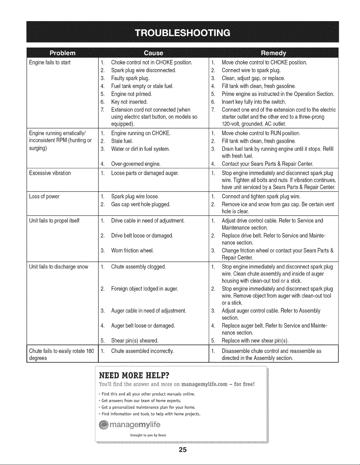
Enginefails to start
Enginerunningerratically/
inconsistentRPM(huntingor
surging)
Excessivevibration
Lossof power
Unitfailsto propel itself
Unitfailsto dischargesnow
1. Chokecontrolnot inCHOKEposition.
2. Sparkplugwire disconnected.
3. Faultysparkplug.
4. Fueltank emptyor stalefuel.
5. Enginenot primed.
6. Keynot inserted.
7. Extensioncordnot connected(when
usingelectricstartbutton,on modelsso
equipped).
1. Enginerunningon CHOKE.
2. Stalefuel.
3. Wateror dirt in fuel system.
4. Over-governedengine.
1. Loosepartsor damagedauger.
1. Sparkplugwire loose.
2. Gascap ventholeplugged.
1. Drivecable inneedof adjustment.
2. Drivebelt looseor damaged.
3. Wornfrictionwheel.
1. Chuteassemblyclogged.
2. Foreignobjectlodgedin auger.
3. Augercablein needof adjustment.
4. Augerbelt looseordamaged.
5. Shearpin(s) sheared.
1. Chuteassembledincorrectly.
1. Movechokecontrolto CHOKEposition.
2. Connectwireto sparkplug.
3. Clean,adjustgap,or replace.
4. Filltank with clean,freshgasoline.
5. Primeengineas instructedin the OperationSection.
6. Insertkeyfully intothe switch.
7. Connectoneendof the extensioncordto the electric
starteroutletandthe otherendto a three-prong
120-volt,grounded,ACoutlet.
1. Movechokecontrolto RUNposition.
2. Filltank with clean,freshgasoline.
3. Drainfueltank by runningengineuntil it stops.Refill
withfreshfuel.
4. ContactyourSearsParts & RepairCenter.
1. Stopengineimmediatelyand disconnectsparkplug
wire.Tightenall boltsand nuts.If vibrationcontinues,
haveunit servicedbya SearsParts& RepairCenter.
1. Connectandtightensparkplugwire.
2. Removeiceand snowfromgascap. Be certainvent
holeis clear.
1. Adjustdrivecontrolcable. Referto Serviceand
Maintenancesection.
2. Replacedrive belt.Referto Serviceand Mainte-
nancesection.
3. Changefrictionwheelorcontactyour SearsParts&
RepairCenter.
1. Stopengineimmediatelyand disconnectsparkplug
wire.Cleanchuteassemblyand insideof auger
housingwith clean-outtoolor a stick.
2. Stopengineimmediatelyand disconnectsparkplug
wire.Removeobjectfrom augerwith clean-outtool
ora stick.
3. Adjustaugercontrolcable. Referto Assembly
section.
4. Replaceauger belt. Referto Serviceand Mainte-
nancesection.
5. Replacewith newshearpin(s).
Chutefailsto easily rotate 180 1. Disassemblechutecontroland reassembleas
degrees directedinthe Assemblysection.
NEED HORE HELP?
Yot,Fttfind. th_ answer a!ld mo_e on ma_age_y_ifeocom _ for free]
Find this and att your other product manua[s ontine.
Get answers from our team of home experts.
Get a personalized maintenance p[an for your home.
Find information and tools to he[p with home projects.
managemylife
b_e'_g_t_/_eyeu by Sea_s
25
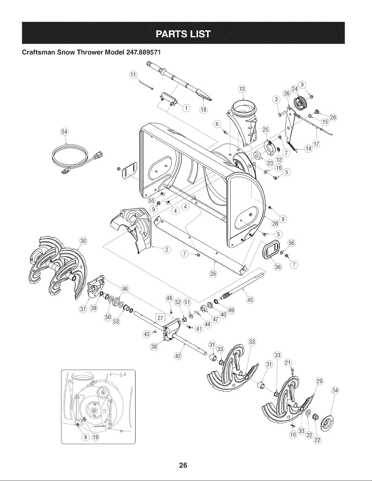
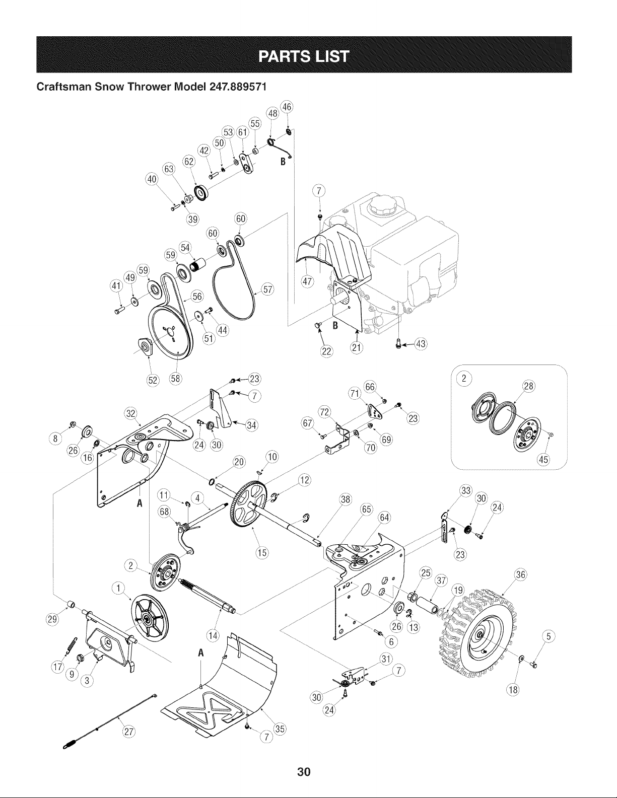
Craftsman Snow Thrower IViodel 247.889571
I
i
/
,// ///'
/
26
Craftsman Snow Thrower IViodel 247.889571
D = 0 0
731-2635 SnowRemovalToolMount
2. 684-04057A-0637 ImpellerAssembly,12"Dia.
3. 710-0347 HexScrew,3/8-16,1.75,Gr5
4. 710-0451 Bolt,Carriage,5/16-18,.750Grl
5. 710-04484 Screw, 5/16-18,0.750
6. 710-0703 Screw,Carriage,1/4-20,.750,Gr5
7. 712-04063 Nut,FlangeLock,5/16-18,Nylon
8. 712-04064 Nut,FlangeLock,1/4-20,Nylon
9. 712-04065 Nut,FlangeLock,3/8-16,Nylon
10. 714-04040 CotterPin,Bow-tie
11. 725-0157 Cable,Tie, 3/16 x .05 x 7.4
12. 926-04012 Nut,Push-on,.25 Dia
13. 731-04705D Chute,Adapter5" Dia
14. 732-04460 Spring,Extension,.38 ODx 4.59
15. 736-0174 Washer,Wave,.625x .885x .015
16. 736-0242 Washer,Bell,.340x .872x .060
17. 746-04230 ClutchCable,Auger,47.23"
18. 931-2643 SnowRemovalTool
19. 738-0143 Screw,Shoulder,.498x .34,3/8-16
20. 938-0281 Screw,Shoulder,.625x .17,3/8-16
21. 738-04124A ShearPin,.25 x 1.50
22. 941-0245 Bearing,HexFlangex .75ID
23. 941-0309 Bearing,Ball,.75IDx 1.85OD
24. 756-04224 FlatPulley,Idler, 2.75OD
25. 790-00075 Housing,Bearing,1.85ID
26. 790-00080A-0637 Bracket,AugerIdlerw/Brake
27. 918-04171B GearboxAssembly,Auger,24"
28. 684-04265-4044 HousingAssembly,Auger24"
D = O 0
684-04107-0637 SpiralAssembly,LH
30. 684-04108-0637 SpiralAssembly,RH
31. 731-04870 Spacer,1.25OD x .75 ID x 1.00
32. 736-0188 Washer,Flat, .76x 1.49x .06
33. 741-0493A Bushing,Flange,.80 IDx .91OD
34. 790-00087A-0637 Housing,1"HexBearing
35. 790-00120-4044 ShavePlate,2.25 x 23.66
36. 731-06439 SlideShoe
37. 918-0123A Housing,Auger,RH
38. 918-0124A Housing,Auger,LH
39. 921-0338 Seal,Oil, .750x 1.00x .125
40. 741-0662 Bearing,Flange,.75x 1.0x .59
41. 710-0642 Screw,Self-tapping,1/4-20,0.750
42. 711-04285 Axle,Auger,24"
43. 914-0161 Key,Hi-pro3/16x 5/8
44. 715-04021 Pin, Dowel,.25OD x 1.2
45. 917-04126 Shaft,Worm.75OD
46. 917-04861 Gear,Worm20T
47. 718-04071 Collar,Thrust
48. 721-0325 Plug,1/4 x .437
49. 721-0327 Seal,Oil, .75x 1 x .131
50. 936-0351 Washer,Flat, .760IDx 1.50D
51. 736-3084 Washer,Flat, .51x 1.12
52. 741-0663 Bearing,Flange,.75x 1.0x .925
53. 741-0661A Bearing,Flange,.75x 1.00x .975
54. 929-0071A ExtensionCord,110V
55. 710-0276 Screw,Carriage,5/16-18x 1.00
56. 936-0159 Washer,Fiat, .349x .879x .063
27

Craftsman Snow Thrower Model 247.889571
S_
y:,15,1 _4_,
/
28
Craftsman Snow Thrower IViodel 247.889571
D = " 0
631-04133A HandleAssembly,ClutchLock,LH
2. 631-04134B HandleAssembly,ClutchLock,RH
3. 684-04111B HandleAss'y,Engage,Red,LH
4. 684-04112B HandleAss'y,Engage,Red,RH
5: J 631-04131B J Chute,Lower(/ncl_Ref_#27,Qty. 3)
6. 732-04238 Spring,Torsion,.8156ID x .3038
7. 914-0145 ClickPin
8. 710-04586 Screw,1/4-20x 1.625
9. 790-00219-4044 Panel,Handle,(nocutout)
10. 710-1233 Screw,Machine,#10-24,1.375
11. 731-06471 HandlePanelCover
12. 712-04063 Nut,FlangeLock,5/16-18,Nylon
13. 749-04190A-0637 Handle,Upper,RH
14. 936-0185 Washer,Fiat,.375x .738x .063
15. 720-0274 Grip,1.0IDx 5.0
16. 720-04039 Knob,Shift,Black
17. 735-0234 Grommet,.44 IDx .94 ODx .50
18. 926-0100 Cap,Push,3/8 Rod
19. 732-0193 Spring,.39 x .60 x .88
20. 720-0284 Knob,5/16-18,Black
21. 720-0201A CrankKnob,1.0Dia.x 3.2, Black
22. 749-04138A-0637 Handle,Lower
23. 935-0199A Bumper,Rubber,.62 ODx .22
24. 736-0262 Washer,Fiat,.385x .870x .092
=
25. 738-04118 Bolt,Shoulder,5/16-18x 0.905
26. 738-04348 Screw,Shoulder,.43x 1.3,1/4-20
D = O O
731-04869A Chute,FlangeKeeper
28. 946-04397A Cable,SpeedSelector
29. 749-04191A-0637 Handle,Upper,LH
30. 747-04263 EyeBolt,ChuteCrank
31. 790-00313-0637 Shift Lever
32. 731-04912B Chute,Lower,5.0 Dia.
33. 710-0276 Bolt,Carriage,5/16-18,1.0
34. 710-04071 Bolt,Carriage,5/16-18,1.0
35. 710-0451 Bolt,Carriage,5/16-18,.750
36. 731-04426A Chute,Upper,w/Label
37. 936-0159 Washer,.349x .879x .063
38. 941-0475 Bushing,Plastic,.380
39. 784-5647-0637 Bracket,ChuteCrank
40. 684-04104-0637 CrankAssembly,Chute
41. 710-0449 Screw,Carriage,5/16-18,2.25
42. 710-04484 Screw,5/16-18,2.25, Gr5
43. 914-0104 Pin,Cotter,.072x 1.13
44. 790-00248B-0637 Bracket,Panel
45. 684-04250 Rod,Pivot
46. 710-04326 Screw,#8-16x .50
47. 710-3069 Screw,1/4-20x .50
48. 712-04081A Nut,Hex, 1/4-20
49. 731-04894D Plate,Lock
50. 731-04896B Cam,ClutchLock
51. 732-04219C Spring,ClutchLock
29
Craftsman Snow Thrower IViodel 247.889571
i
/
/
/
/
3O
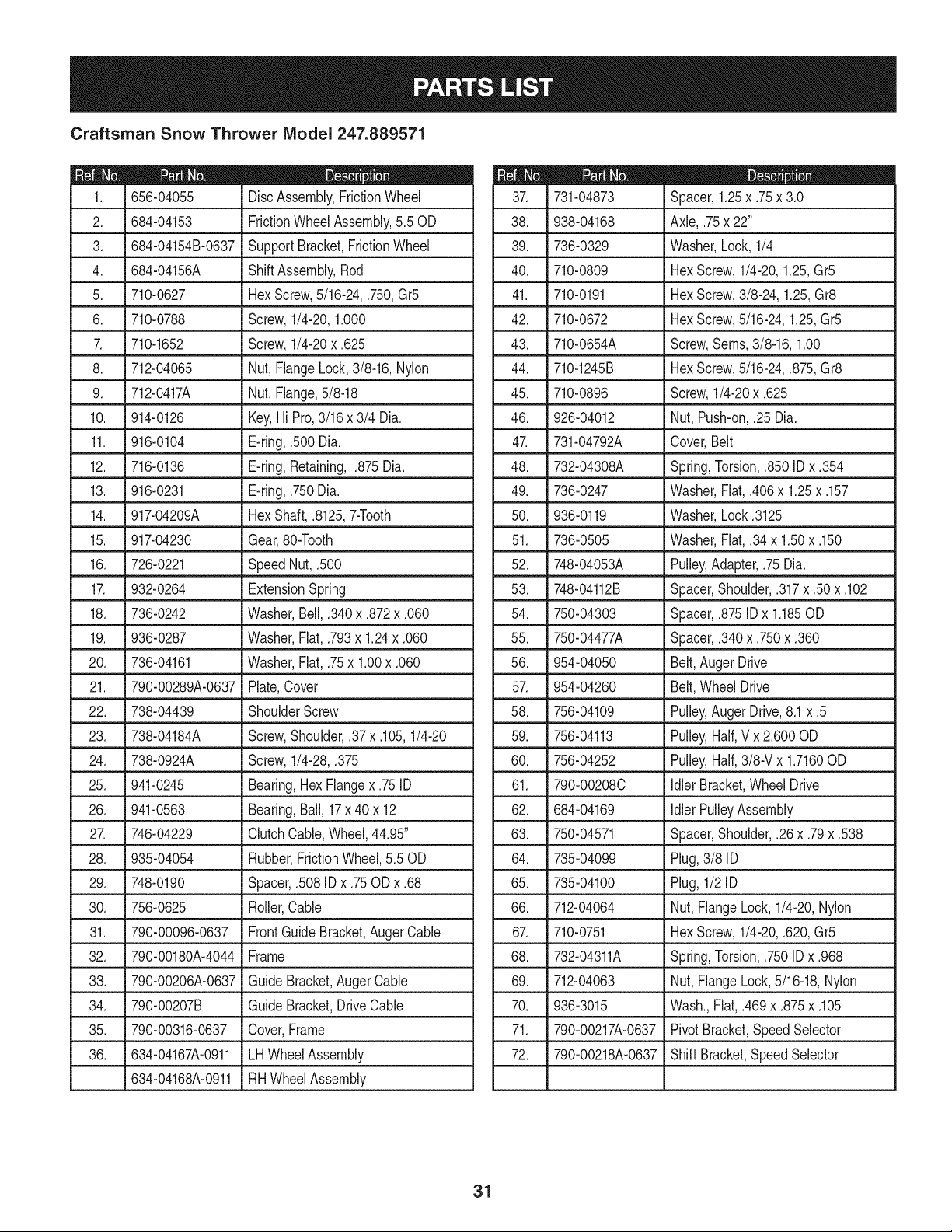
Craftsman Snow Thrower IViodel 247.889571
I = 0 0
656-04055 DiscAssembly,FrictionWheel
2. 684-04153 FrictionWheelAssembly,5.50D
3. 684-04154B-0637 SupportBracket,FrictionWheel
4. 684-04156A ShiftAssembly,Rod
5. J 710-0627 J HexScrew,5/16-24,.750,Gr5
6. 710-0788 Screw,1/4-20,1.000
7. 710-1652 Screw,1/4-20x .625
8. 712-04065 Nut,FlangeLock,3/8-16,Nylon
9. 712-0417A Nut,Flange,5/8-18
10. 914-0126 Key,Hi Pro,3/16x 3/4 Dia.
11. 916-0104 E-ring,.500 Dia.
12. 716-0136 E-ring,Retaining, .875Dia.
13. 916-0231 E-ring,.750Dia.
14. 917-04209A HexShaft,.8125,7-Tooth
15. 917-04230 Gear,80-Tooth
16. .726-0221 Speed Nut,.500
17. 932-0264 ExtensionSpring
18. 736-0242 Washer,Bell,.340x .872x .060
19. 936-0287 Washer,Flat,.793x 1.24x .060
20. 736-04161 Washer,Flat,.75x 1.00x .060
21. 790-00289A-0637 Plate,Cover
22. 738-04439 ShoulderScrew
23. 738-04184A Screw,Shoulder,.37x .105,1/4-20
24. 738-0924A Screw,1/4-28,.375
25. 941-0245 Bearing,HexFlangex .75 ID
26. 941-0563 Bearing,Ball,17x 40x 12
27. 746-04229 ClutchCable,Wheel,44.95"
28. 935-04054 Rubber,FrictionWheel,5.50D
29. 748-0190 Spacer,.508IDx .75OD x .68
30. 756-0625 Roller,Cable
31. 790-00096-0637 FrontGuideBracket,Auger Cable
32. 790-00180A-4044 Frame
33. 790-00206A-0637 GuideBracket,AugerCable
34. 790-00207B Guide Bracket,Drive Cable
35. 790-00316-0637 Cover,Frame
36. 634-04167A-0911 LHWheelAssembly
634-04168A-0911 RHWheelAssembly
D = O e
731-04873 Spacer,1.25x .75x 3.0
38. 938-04168 Axle,.75x 22"
39. 736-0329 Washer,Lock, 1/4
40. 710-0809 HexScrew,1/4-20,1.25,Gr5
41. 710-0191 HexScrew,3/8-24,1.25,Gr8
42. 710-0672 HexScrew,5/16-24,1.25,Gr5
43. 710-0654A Screw,Seres,3/8-16, 1.00
44. 710-1245B HexScrew,5/16-24,.875,Gr8
45. 710-0896 Screw,1/4-20x .625
46. 926-04012 Nut, Push-on,.25 Dia.
47. 731-04792A Cover,Belt
48. 732-04308A Spring,Torsion,.850 ID x .354
49. 736-0247 Washer,Flat, .406x 1.25x .157
50. 936-0119 Washer,Lock.3125
51. 736-0505 Washer,Flat, .34x 1.50x .150
52. 748-04053A Pulley,Adapter,.75 Dia.
53. 748-04112B Spacer,Shoulder,.317x .50 x .102
54. 750-04303 Spacer,.875IDx 1.185OD
55. 750-04477A Spacer,.340x .750x .360
56. 954-04050 Belt,AugerDrive
57. 954-04260 Belt,WheelDrive
58. 756-04109 Pulley,Auger Drive,8.1x .5
59. 756-04113 Pulley,Half,V x 2.600 OD
60. 756-04252 Pulley,Half,3/8-V x 1.7160OD
61. 790-00208C Idler Bracket,Wheel Drive
62. 684-04169 Idler PulleyAssembly
63. 750-04571 Spacer,Shoulder,.26x .79x .538
64. 735-04099 Plug,3/8 ID
65. 735-04100 Plug,1/2 ID
66. 712-04064 Nut, FlangeLock,1/4-20,Nylon
67. 710-0751 HexScrew,1/4-20,.620,Gr5
68. 732-04311A Spring,Torsion,.750IDx .968
69. 712-04063 Nut, FlangeLock,5/16-18,Nylon
70. 936-3015 Wash.,Flat,.469x .875x .105
71. 790-00217A-0637 PivotBracket,SpeedSelector
72. 790-00218A-0637 ShiftBracket,Speed Selector
31
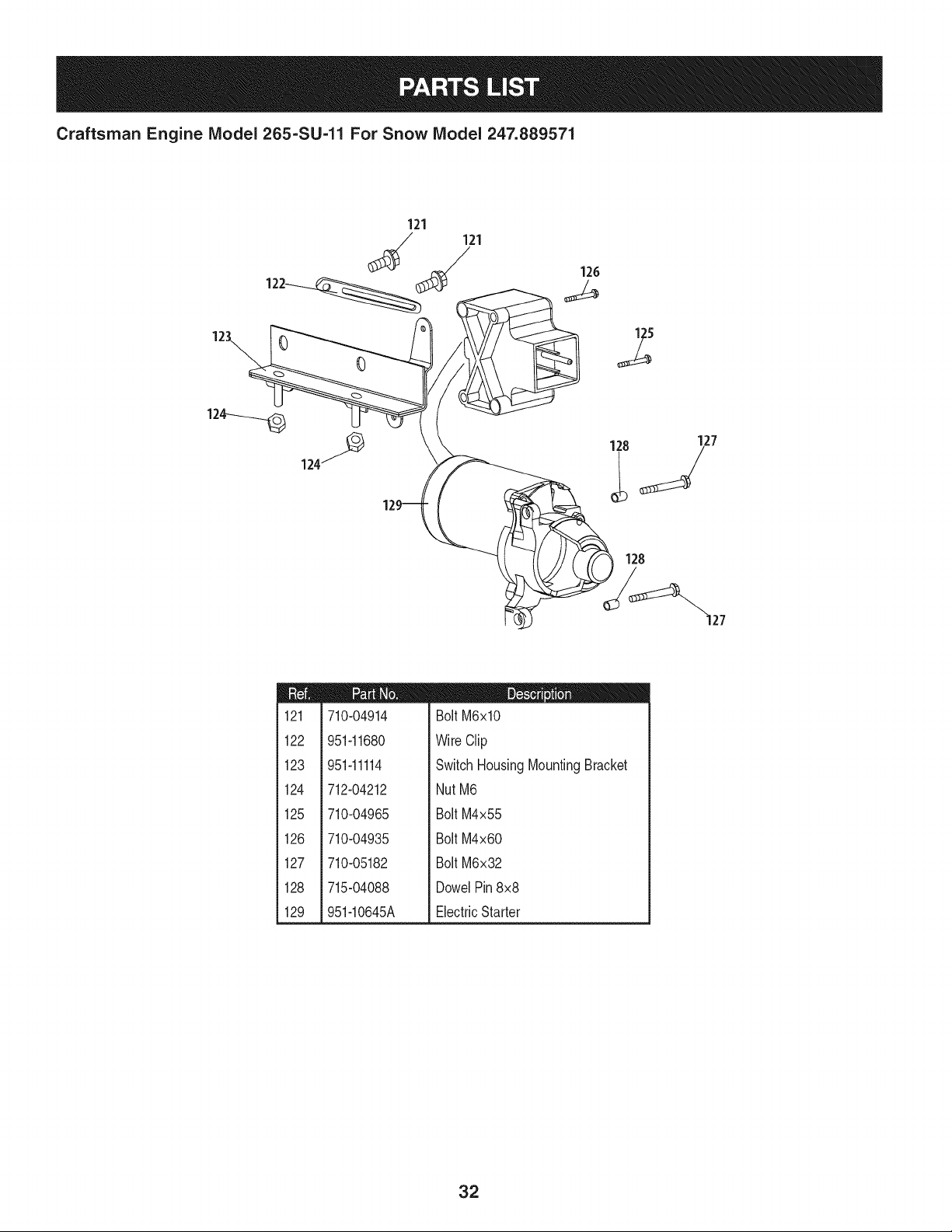
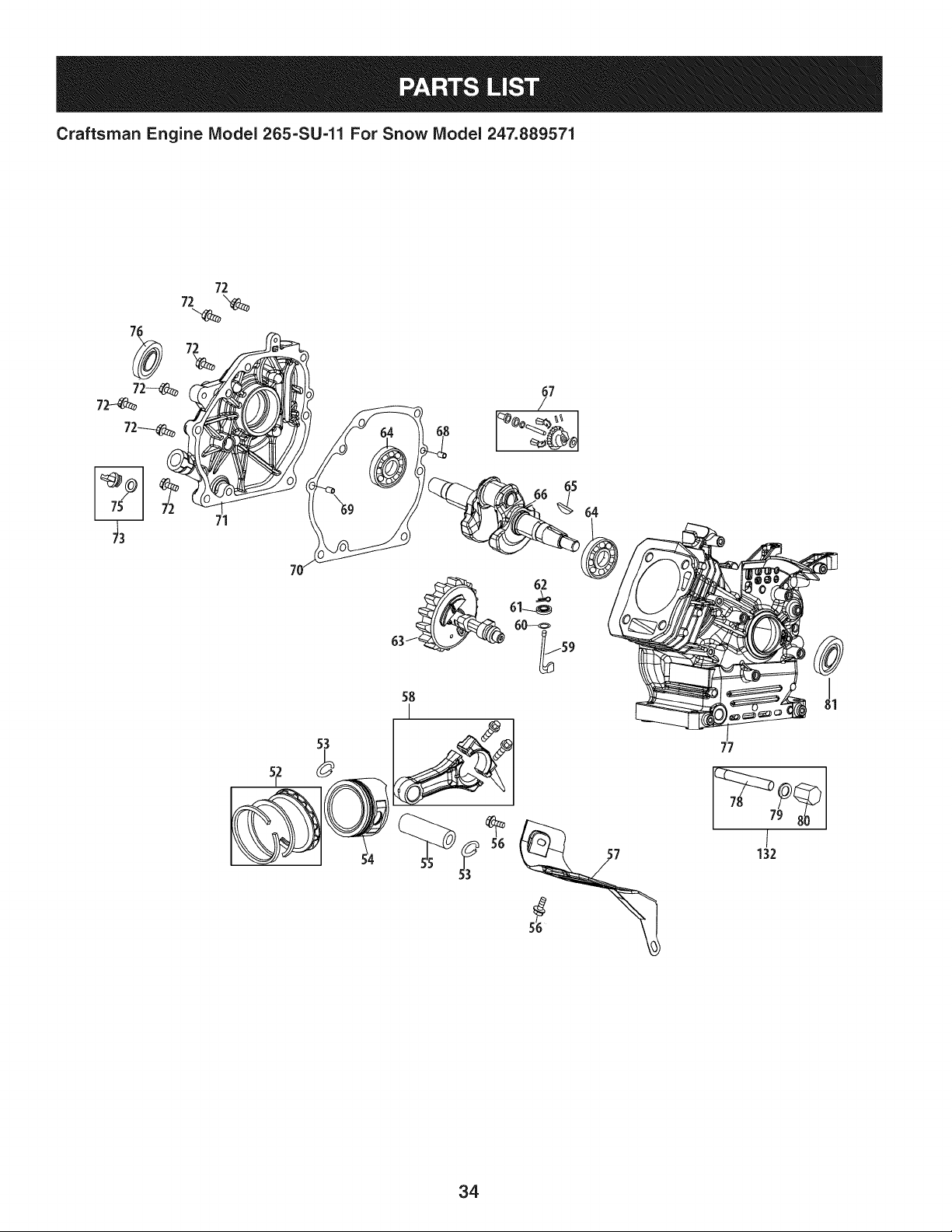
Craftsman Engine Model 265=SU-11 For Snow Model 247.889571
121
121
128
127
S
128
m
i
1121
1
1
1
i 122
!
i
i 123
1
1
1
i 124
!
!
i
i 125
1
1
i 126
1
1
1
i 127
!
i
1
i 128
1
i 129
710-04914
951-11680
951-11114
712-04212
710-04965
710-04935
710-05182
715-04088
951-10645A
D = W I
Bolt M6xlO
WireClip
SwitchHousingMountingBracket
NutM6
Bolt M4x55
Bolt M4x60
Bolt M6x32
DowelPin8x8
ElectricStarter
32
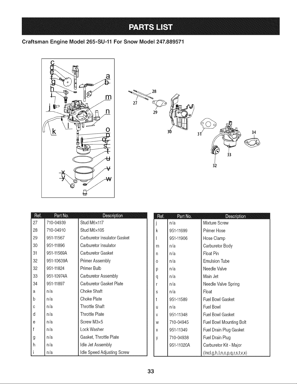
Craftsman Engine IViodel 265=SU=11 For Snow IViodel 247.889571
a
m
o
3Z
m
27
28
29
30
31
32
32
33
34
a
b
C
d
e
f
g
h
I
710-04939
710-04910
951-11567
951-11896
951-11569A
951-10639A
951-11824
951-10974A
951-11897
n/a
n/a
n/a
n/a
n/a
n/a
n/a
n/a
n/a
D = I! O
Stud M6x117
Stud M6x105
CarburetorInsulatorGasket
CarburetorInsulator
CarburetorGasket
PrimerAssembly
PrimerBulb
CarburetorAssembly
CarburetorGasketPlate
ChokeShaft
ChokePlate
ThrottleShaft
ThrottlePlate
ScrewM3x5
LockWasher
Gasket,ThrottlePlate
IdleJetAssembly
IdleSpeedAdjustingScrew
m
J
k
I
I11
n
O
P
q
r
s
t
U
V
W
X
Y
n/a
951-11699
951-11906
n/a
n/a
n/a
n/a
n/a
n/a
n/a
951-11589
n/a
951-11348
710-04945
951-11349
710-04938
951-11020A
I = I! O
MixtureScrew
PrimerHose
HoseClamp
CarburetorBody
FloatPin
EmulsionTube
NeedleValve
MainJet
NeedleValveSpring
Float
FuelBowlGasket
FuelBowl
FuelBowlGasket
FuelBowlMountingBolt
FuelDrainPlugGasket
FuelDrainPlug
CarburetorKit- Major
(Incl.g,h,l,n,o,p,q,r,s,t,v,x)
33
Craftsman Engine IViodel 265=SU=11 For Snow IViodel 247.889571
72
72
71
58
53
77
/
132
34
Craftsman Engine IViodel 265-SU-11 For Snow IViodel 247.889571
m
i
152
i
i
i
153
i
i
i
i54
!
i
155
i
i
i
156
i
i
i
i57
!
i
158
i
i
i
i59
!
i
i
160
i
i
161
i
i
i
i62
!
i
i
163
i
i
164
i
i
i
i65
!
i
166
i
i
i
i
i
i
i
i67
!
i
i68
!
!
i
169
i
i
170
i
i
i
i71
!
i
i
172
i
951-11688
951-11632
951-11900
951-11901
710-04915
951-11113
951-11573
951-11356
736-04461
951-11902
714-04074
951-11575
951-11369
951-10307
951-11247A
951-11576
715-04092
715-04089
951-11371
951-12125
710-04932
m = O O
PistonRingSet
PistonPinSnapRing
Piston
PistonPin
BoltM6x12
Air Shield
ConnectingRodAssembly
GovernorArmShaft
Washer5.2xl.9
GovernorSeal
CotterPin
CamshaftAssy.
RadialBall Bearing
WoodruffKey
CrankshaftKit
(Incl.64-66,76,79)
GovernorGear/ShaftAssembly
DowelPin7x14
DowelPin9x14
CrankcaseCoverGasket
CoverComp,Left Crankcase
BoltM8x32
m
73
75
76
77
78
79
8O
81
132
951-11283
951-11577
951-11368
951-11248A
951-11350
736-04440
710-04906
951-11370
951-10641
952Z265-SU-11
951-11246
951-10661B
951-11062B
951-11061A
D = O O
OilFill PlugAssembly
O-Ring15.8x2.5
OilSeal25x41.25x6
CrankcaseKit
(Incl.61,64,76,77,79)
OilDrainPipeAssy.
Washer10x16x1.5
OilDrainPlug
OilSeal25x41.25x6
OilDrainAssembly
CompleteEngine
CrankcaseCoverKit
(Incl.64,70-72,74-76)
GasketKit- External
(Incl.4,21,29-31,34,79)
ShortBlock
(Incl.4,21,29,30,46,48,
49,52-55,58-81)
GasketKit- Complete
(Incl.4,21,29-31,34,46,
60,61,70,76,79,80)
35
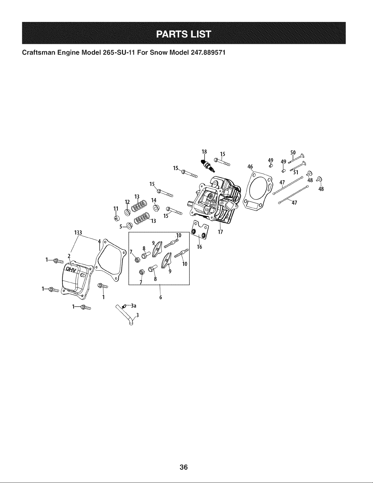
Craftsman Engine IViodel 265=SU=11 For Snow IViodel 247.889571
1
5O
36
Craftsman Engine IViodel 265=SU=11 For Snow IViodel 247.889571
m
1
2
3
3a
4
5
6
7
8
9
10
11
12
13
14
15
16
17
710-04744
951-11054
731-07059
726-04101
951-11565
951-12000
951-11892
751-11124
751-11123
951-11893
710-04902
951-12002
951-12003
951-12004
951-11894
710-04933
951-11895
951-10722A
D = B 0
BoltM6x16
ValveCover
BreatherHose
HoseClamp
ValveCoverGasket
Retainer,In.ValveSpring
RockerArmAssembly
Nut,PivotLocking
AdjustingNut,Valve
RockerArm
Bolt,Pivot
Adjuster,ExhValve
Retainer,Ex.ValveSpring
ValveSpring
IntakeValveSeal
BoltM8x55
PushRodGuide
CylinderHeadAssembly
(Incl.4,5,7-14,16,17,21,
29,30,46,50,51)
m
18
46
47
48
49
5O
51
133
951-10292
951-11898
951-10648
951-11899
715-04090
951-10647A
951-10647A
951-11063A
m = O O
SparkPlug/F6Rtc
Gasket,CylinderHead
PushRodKit
Tappet
DowelPin,10x16
ValveKit
ValveKit
ValveCoverKit
952Z265-SU-11
951-10661B
951-11062B
951-11061A
CompleteEngine
GasketKit- External
(Incl.4,21,29-31,34,79)
ShortBlock
(Incl.4,21,29,30,46,48,
49,52-55,58-81)
GasketKit- Complete
(Inc1.4,21,29-31,34,46,
60,61,70,76,79,80)
37
Craftsman Engine IViodel 265=SU=11 For Snow IViodel 247.889571
87
m
82
83
84
85
87
88
89
90
91
93
94
95
96
96
130
131
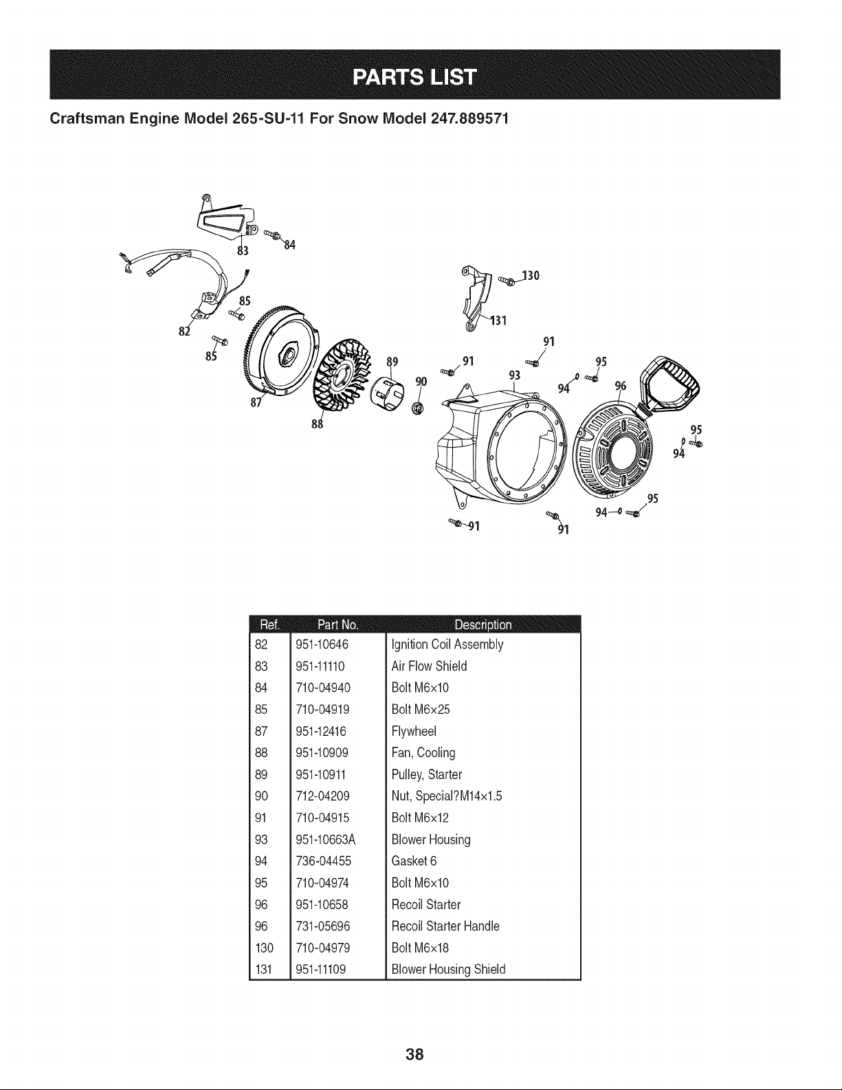
951-10646
951-11110
710-04940
710-04919
951-12416
951-10909
951-10911
712-04209
710-04915
951-10663A
736-04455
710-04974
951-10658
731-05696
710-04979
951-11109
D = O O
IgnitionCoil Assembly
Air FlowShield
BoltM6xlO
BoltM6x25
Flywheel
Fan,Cooling
Pulley,Starter
Nut,Special?M14x1.5
BoltM6x12
BlowerHousing
Gasket6
BoltM6xlO
RecoilStarter
RecoilStarterHandle
BoltM6x18
BlowerHousingShield
38
Craftsman Engine Model 265=SU-11 For Snow Model 247.889571
105
108 109
\
112-% t/ z 111
m
97
98
99
1CO
101
102
104
105
106
107
108
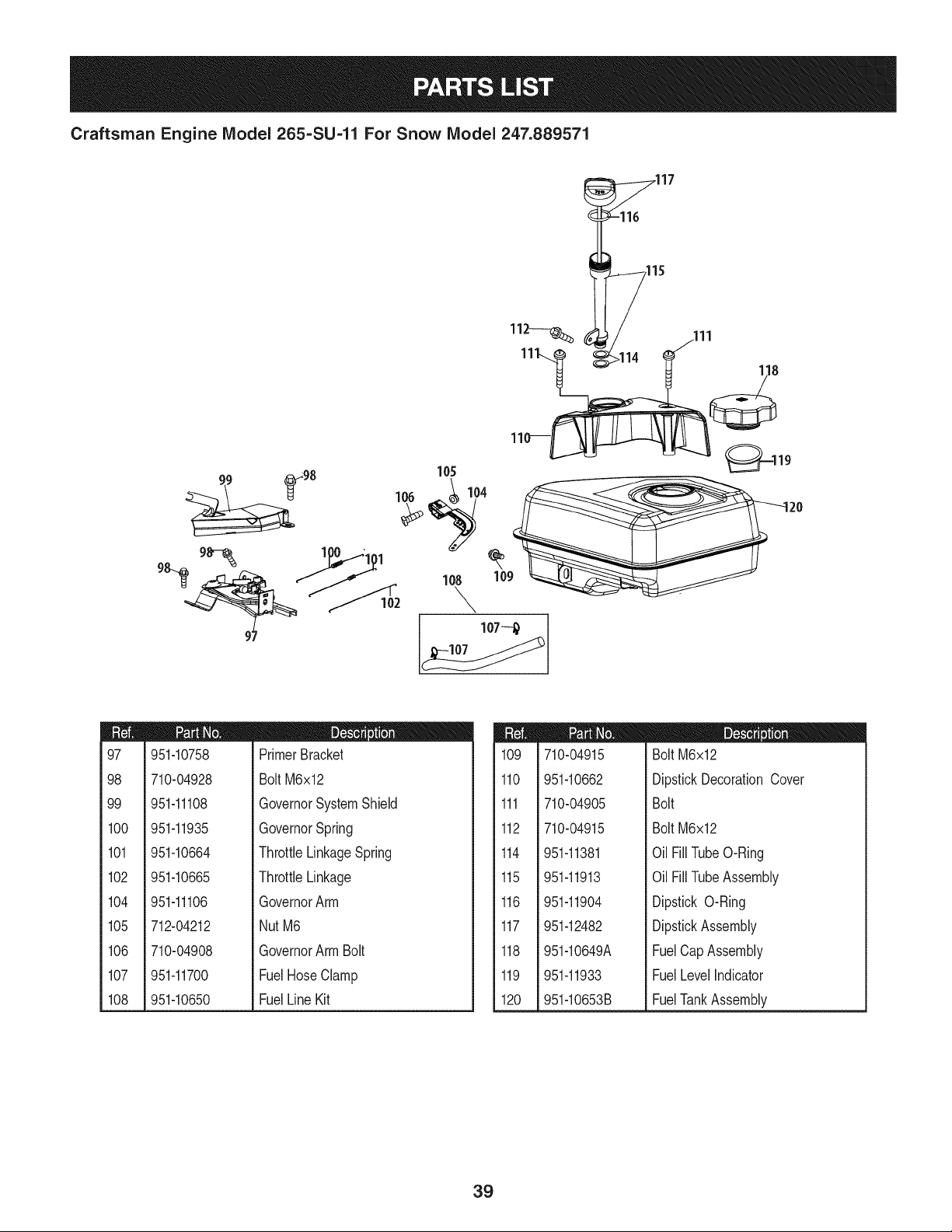
951-10758
710-04928
951-11108
951-11935
951-10664
951-10665
951-11106
712-04212
710-04908
951-11700
951-10650
D = O
PrimerBracket
BoltM6x12
GovernorSystemShield
GovernorSpring
ThrottleLinkageSpring
ThrottleLinkage
GovernorArm
NutM6
GovernorArmBolt
FuelHoseClamp
FuelLineKit
m
109
110
111
112
114
115
116
117
118
119
120
710-04915
951-10662
710-04905
710-04915
951-11381
951-11913
951-11904
951-12482
951-10649A
951-11933
951-10653B
D = O O
Bolt M6x12
DipstickDecorationCover
Bolt
Bolt M6x12
Oil FillTubeO-Ring
Oil FillTubeAssembly
Dipstick O-Ring
DipstickAssembly
FuelCapAssembly
FuelLevelIndicator
FuelTankAssembly
39
Craftsman Engine IViodel 265=SU=11 For Snow IViodel 247.889571
m
19
20
20
21
22
23
24
25
26
34
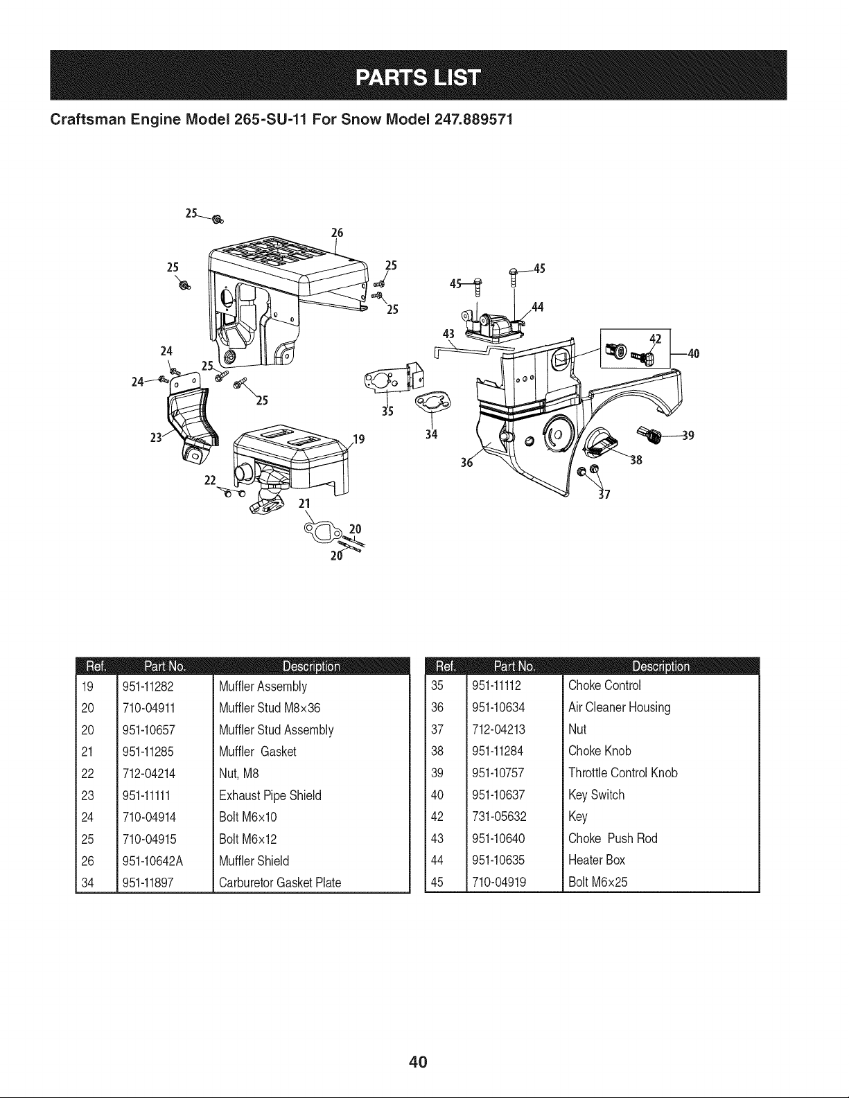
951-11282
710-04911
951-10657
951-11285
712-04214
951-11111
710-04914
710-04915
951-10642A
951-11897
D = O O
MufflerAssembly
MufflerStud M8x36
MufflerStudAssembly
Muffler Gasket
Nut,M8
ExhaustPipe Shield
BoltM6xlO
BoltM6x12
MufflerShield
CarburetorGasketPlate
m
35
36
37
38
39
4O
42
43
44
45
951-11112
951-10634
712-04213
951-11284
951-10757
951-10637
731-05632
951-10640
951-10635
710-04919
D = O O
ChokeControl
Air CleanerHousing
Nut
ChokeKnob
ThrottleControlKnob
KeySwitch
Key
Choke PushRod
HeaterBox
BoltM6x25
4O
Craftsman Engine Model 265=SU-11 For Snow Model 247.889571
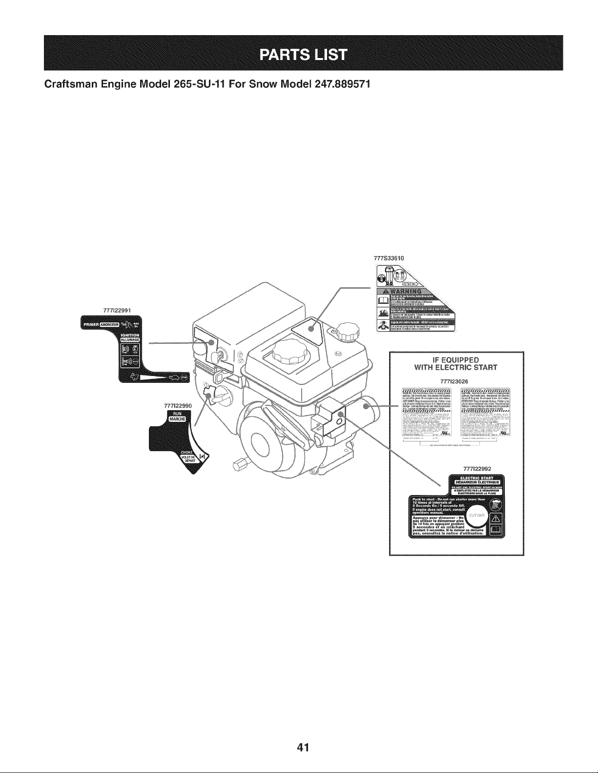
777533610
777U22991
777J22992
41
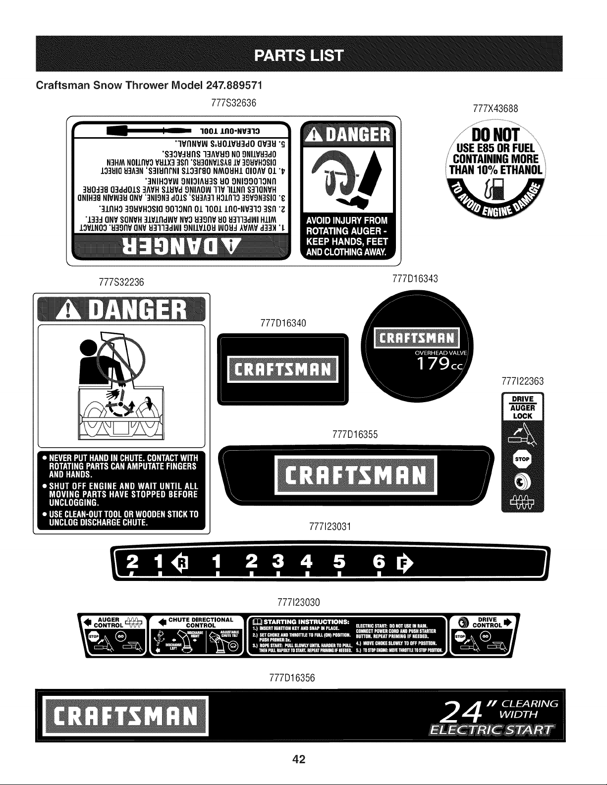
Craftsman Snow Thrower Niodel 247.889571
777S32636 777X43688
"1001IAO-NV:r'IO
"'IVnNVlNS,I:IOLVEI3clOOV3U"S
"S30VJEInS33AVEI9NO9NIIVEI3dO
N3HMNOIlnVoVEIIX33sn"SU]ONVS.SX8iV:IOEIVHOSIO
103910EI3A::IH'S31EInI'NIS.LO3rsoNMOEIHIOIOAVO/"'17
"3NIHOVIt,]9NIOIAEFISEIO9NI990IONn
3E10-138O3clclO.LS3AVHSIEIVd9NIAOINllP II.LNnS:IIONVH
ONIH38NIVIN3EIONV'3NIgN3dO.L$'SEI3A3IHO.l.n]o:19¥9N3$10"£
"31flHO39EIVHO$1090lONn 011001 IAO-NV3"IO3$fl "g
"133::10NVSONVH:I.LVIndWVNVOEFIgnvEIOEIq'l13dlNIHIIM
IOVINO0u:lgnv ONVEI3IFIdlNI9NIIVIOUINOEI-IAVMVd:13H•I.
777S32236
J
777D16343
777D16340
777122363
777D16355
777123031
777123030
I
777D16356
42

43
MTD CONSUMER GROUP INC (MTD), the California Air Resources Board (CARB)
and the United States Environment Protection Agency (U. S. EPA)
Emission Control System Warranty Statement
(Owner's Defect Warranty Rights and Obligations)
EMISSIONCONTROLSYSTEMCOVERAGEIS APPLICABLETOCERTIFIEDENGINESPURCHASEDINCALIFORNIAIN 2005 ANDTHERE-
AFTER,WHICHARE USEDINCALIFORNIA,ANDTO CERTIFIEDMODELYEAR2005ANDLATERENGINESWHICHARE PURCHASEDAND
USEDELSEWHEREIN THE UNITEDSTATES.
Californiaandelsewherein the UnitedStatesEmissionControlDefectsWarrantyCoverage
The CaliforniaAir ResourcesBoard(CARB),U. S. EPAandMTDarepleasedto explaintheemissionscontrol systemwarrantyon your modelyear
2006andlatersmalloff-roadengine.In California,new smalloff-roadenginesmustbe designed,builtand equippedto meet theStatesanti-smog
standards.Elsewherein the UnitedStates,newnon-road,spark-ignitionenginescertifiedfor model2005and later,mustmeetsimilarstandardsset
forthby the U.S. EPA.MTDmustwarrantythe emissioncontrolsystemon yourenginefor the periodof timelistedbelow,providedtherehasbeen
noabuse,neglector impropermaintenanceof your smalloff-roadengine.
Youremissioncontrolsystemmayincludepartssuch as the carburetor,fuel-injectionsystem,the ignitionsystem,and catalyticconverter,fueltanks,
fuel lines,fuel caps,valves,canisters,filters,vaporhoses,clamps,connectors,andotherassociatedemission-relatedcomponents.
Wherea warrantableconditionexists,MTDwill repairyoursmalloff-roadengineat nocost to yourincludingdiagnosis,partsand labor.
MANUFACTURER'S WARRANTY COVERAGE:
Thisemissionscontrolsystemis warrantedfor two years.If anyemission-relatedpart onyourengineis defective,the part will berepairedor
replacedby MTD.
OWNER'S WARRANTY RESPONSIBILITIES:
As the smalloff-roadengineowner,youare responsibleforthe performanceof the requiredmaintenancelistedinyour Owner'sManual.MTD
recommendsthatyou retainall yourreceiptscoveringmaintenanceson yoursmalloff-roadengine,but MTDcan not denywarrantysolelyfor the
lackof receiptsor foryour failureto ensurethe performanceto allscheduledmaintenance.
As the smalloff-roadengineowner,youshouldhoweverbe awarethat MTDmaydenyyour warrantycoverageif yoursmalloff-roadengineorpart
hasfaileddue toabuse,neglect,impropermaintenanceor unapprovedmodifications.
Youare responsiblefor presentingyour smalloff-roadengineto an AuthorizedMTDServiceDealeras soonas a problemexists.Thewarranted
repairsshouldbe completedina reasonableamountof time,notto exceed30 days.
Ifyou haveanyquestionsregardingyourwarrantyrightsand responsibilities,you shouldcontacta MTDService Representativeat 1-800-800-7310
andaddressis MTDCONSUMERGROUP,RO.Box361131,ClevelandOH,44136-0019.
DEFECTS WARRANTY REQUIREMENTS FOR 1995 AND LATER SMALL OFF-ROAD ENGINES:
Thissectionappliesto 1995and later smalloff-roadengines.The warrantyperiodbeginson the datethe engineor equipmentis deliveredto an
ultimatepurchaser.
(a) GeneralEmissionsWarrantyCoverage
MTDmustwarrantto the ultimatepurchaserandeachsubsequentpurchaserthat the engineis:
(1)Designed,built,and equippedsoas to conformwithall applicableregulationsadoptedby the AirResourcesBoardpursuantto its authorityin
Chapters1 and 2,Part 5, Division26 of the HealthandSafetyCode;and
(2) Freefromdefectsin materialsandworkmanshipthatcausethe failureof a warrantedpart to be identicalin all materialrespectsto the partas
describedin theenginemanufacturer'sapplicationfor certificationfora periodof twoyears.
(b)The warrantyonemissions-relatedpartswill be interpretedas follows:
(1)Anywarrantedpart that is not scheduledfor replacementas requiredmaintenanceinthe writteninstructionsrequiredby Subsection(c)
mustbe warrantedfor the warrantyperioddefinedinSubsection(a)(2). Ifany such partfails duringthe periodof warrantycoverage,it mustbe
repairedor replacedby MTDaccordingto Subsection(4)below.Anysuchpart repairedor replacedunder thewarrantymustbe warrantedfor
the remainingwarrantyperiod.
(2)Any warrantedpartthat is scheduledonlyfor regularinspectionin the writteninstructionsrequiredby Subsection(c) must be warrantedfor
thewarrantyperioddefinedin Subsection(a)(2).A statementinsuchwritteninstructionsto the effectof "repairor replaceas necessary"will
not reducethe periodof warrantycoverage.Anysuch part repairedor replacedunderwarrantymustbe warrantedforthe remainingwarranty
period.
(3) Anywarrantedpartthat whichis scheduledfor replacementas requiredmaintenancein the writteninstructionsrequiredby Subsection(c)
mustbe warrantedfor the periodof timepriorto the first scheduledreplacementpointforthat part.Ifthe part fails priorto thefirst scheduled
replacement,the part mustbe repairedor replacedby MTDaccordingto Subsection(4) below.Any suchpart repairedor replacedunder
warrantymustbe warrantedfor the remainderof the period priorto the first scheduledreplacementpointfor the part.
(4)Repairorreplacementofanywarrantedpartunderthewarrantyprovisionsofthisarticlemustbeperformedatnochargetotheownerata
warrantystation.
(5)NotwithstandingtheprovisionsofSubsection(4)above,warrantyservicesorrepairsmustbeprovidedatallMTDdistributioncentersthat
arefranchisedtoservicethesubjectengines.
(6)Theownermustnotbechargedfordiagnosticlaborthatleadstothedeterminationthatawarrantedpartisinfactdefective,providedthat
suchdiagnosticworkisperformedatawarrantystation.
(7)Theenginemanufacturerisliablefordamagestootherenginecomponentsproximatelycausedbyafailureunderwarrantyofanywarranted
part.
(8)Throughouttheengine'swarrantyperioddefinedinSubsection(a)(2),MTDwillmaintainasupplyofwarrantedpartssufficienttomeetthe
expecteddemandforsuchparts.
(9)Anyreplacementpartmaybeusedintheperformanceofanywarrantymaintenanceorrepairsandmustbeprovidedwithoutchargetothe
owner.SuchusewillnotreducethewarrantyobligationsofMTD.
(10)Add-onormodifiedpartsthatarenotexemptedbytheAirResourcesBoardmaynotbeused.Theuseofanynon-exemptedadd-onor
modifiedpartsshallbegroundsfordisallowingawarrantyclaimmadeinaccordancewiththisarticle.Theenginemanufacturershallnotbe
liableunderthisarticletowarrantfailuresofwarrantedpartscausedbytheuseofnon-exemptedadd-onormodifiedpart.
(c) MTDwill includea copyof the followingemissionwarrantyparts list with each newengine,usingthose portionsof the list applicableto the
e__&gine.
(1)FuelMeteringSystem
• Coldstart enrichmentsystem(soft choke)
,,Carburetorandinternalparts
• Fuel Pump
• FuelTank
(2)Air InductionSystem
• Air cleaner
• Intakemanifold
(3) IgnitionSystem
• Sparkplug(s)
• MagnetoIgnitionSystem
(4)ExhaustSystem
Catalyticconverter
• SAI (Reedvalve)
(5) MiscellaneousItemsUsedin AboveSystem
Vacuum,temperature, position,timesensitivevalvesand switches
Connectorsand assemblies
(6) Evaporativecontrol
• Fuel Hosecertifiedfor ARBevaporativeemissionof 2006.
• Fuel HoseClamps
Tetheredfuel cap
Carboncanister
Vaporlines
GD0C-100174Rev.B
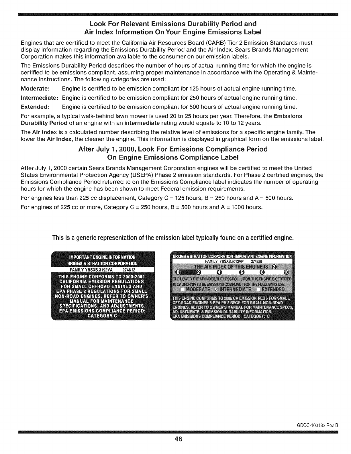
Look For Relevant Emissions Durability Period and
Air index information On Your Engine Emissions Label
Engines that are certified to meet the California Air Resources Board (CARB) Tier 2 Emission Standards must
display information regarding the Emissions Durability Period and the Air Index. Sears Brands Management
Corporation makes this information available to the consumer on our emission labels.
The Emissions Durability Period describes the number of hours of actual running time for which the engine is
certified to be emissions compliant, assuming proper maintenance in accordance with the Operating & Mainte-
nance Instructions. The following categories are used:
Moderate: Engine is certified to be emission compliant for 125 hours of actual engine running time.
Intermediate: Engine is certified to be emission compliant for 250 hours of actual engine running time.
Extended: Engine is certified to be emission compliant for 500 hours of actual engine running time.
For example, a typical walk-behind lawn mower is used 20 to 25 hours per year. Therefore, the Emissions
Durability Period of an engine with an intermediate rating would equate to 10 to 12 years.
The Air index is a calculated number describing the relative level of emissions for a specific engine family. The
lower the Air Index, the cleaner the engine. This information is displayed in graphical form on the emissions label.
After July 1,2000, Look For Emissions Compliance Period
On Engine Emissions Compliance Label
After July 1, 2000 certain Sears Brands Management Corporation engines will be certified to meet the United
States Environmental Protection Agency (USEPA) Phase 2 emission standards. For Phase 2 certified engines, the
Emissions Compliance Period referred to on the Emissions Compliance label indicates the number of operating
hours for which the engine has been shown to meet Federal emission requirements.
For engines less than 225 cc displacement, Category C = 125 hours, B = 250 hours and A = 500 hours.
For engines of 225 cc or more, Category C = 250 hours, B = 500 hours and A = 1000 hours.
This is a generic representation of the emission label typically found on a certified engine.
FAMILYYBSXS.3192VA 274812
GDOC-100182Rev.B
46
Congratulations on making a smart purchase. Your new Craftsman® product is designed and
manufactured for years of dependable operation. But like all products, it may require repair
from time to time. That's when having a Repair Protection Agreement can save you money and
aggravation.
Here's what the Repair Protection Agreement* includes:
[] Expert service by our 10,000 professional repair specialists
[] Unlimited service and no charge for parts and labor on all covered repairs
[] Product replacement up to $1500 if your covered product can't be fixed
[] Discount of 25% from regular price of service and related installed parts not covered by the
agreement; also, 25% off regular price of preventive maintenance check
[] Fast help by phone - we call it Rapid Resolution - phone support from a Sears representative.
Think of us as a "talking owner's manual."
Once you purchase the Repair Protection Agreement, a simple phone call is all that it takes for you
to schedule service. You can call anytime day or night, or schedule a service appointment online.
The Repair Protection Agreement is a risk-free purchase. If you cancel for any reason during the
product warranty period, we will provide a full refund. Or, a prorated refund anytime after the
product warranty period expires. Purchase your Repair Protection Agreement today!
Some limitations and exclusions apply. For prices and additional information in the U.S.A.
call 1=800=827=6655.
*Coverage in Canada varies on some items. For full details call Sears Canada at 1=800=361=
6665.
Sears Installation Service
For Sears professional installation of home appliances, garage door openers, water heaters, and
other major home items, in the U.S.A. or Canada call 1=800=4=MY=HOME®.
47
Declaraci6n de garantia ............................ Pagina 48
Practicas operaci6n seguras ..................... Pagina 49
Montaje ...................................................... Pagina 53
Operaci6n .................................................. Pagina 57
Servicio y Mantenimiento .......................... Pagina 61
Almacenamiento fuera de temporada ....... Pagina 69
Soluci6n de problemas .............................. Pagina 70
Acuerdo de protecci6n para reparaciones .... Pagina 75
Lista de piezas ........................................... Pagina 26
NOmero de servicio ................................... Cubierta
posterior
GARANTiA COMPLETA CRAFTSMAN POR DOS AltOS
PORDOSANOSa partir dela fechade lacornpra,esteproductoest,.garantizadopordefectosen los rnaterialesy la rnanodeobra.
Los productosdefectuososser_.nreparadossin costoo reernplazadossin costosi la reparaci6nnoest,.disponiNe.
La presentegarantiase anulasi se utilizaesteproductoalgunavezparaprestarservicioscornercialeso si se Ioalquilaa otra persona.
Paraobtener informaci6nsobre el alcancede la garantiay solieitar la reparaci6no el reemplazo,visite el sitio Web:www.craftsman.com
Esta garantia cubre0NICAMENTElos defectos en los rnaterialesy en la rnano de obra. Esta garantia NOcubre:
• Elernentosno renovablesque puedendesgastarsepor eluso normal,duranteel plazodela garantia,incluyendoentreotros,las barrenas,
las paletasde las barrenas,los cortadoresde desplazarniento,laszapatasantideslizantes,la placade raspado,lospasadoresde cuchilla,
la bujia,elfiltrode aire,las correasy el filtrodeaceite.
• Serviciosde rnantenirnientoest_.ndar,carnbiosde aceiteo afinaci6n.
• Carnbiode neurn_.ticoso reparacionespor pinchadurascon objetosexternoscornoclavos,espinas,toconeso vidrios.
• Reernplazoo reparaci6nde neurn_.ticoso ruedascornoresultadodel desgastenormal,unaccident&o funcionarniento
o rnantenirnientoincorrectos.
• Reparacionesrequeridascornoresultadodel uso inadecuadopot partedeloperador,incluyendoentreotros el da_oocasionadopor objetos
queirnpactanla rn_.quinay que tuercenel bastidor,el eje de labarrena,etc., o debido a queel motorrueaceleradoenexceso.
• Reparacionesnecesariasdebidoa negligenciadeloperador,incluyendoentre otros,da_osrnec_.nicoy el_ctricoocasionadopor
unalrnacenarnientonoapropiado,fallapor el uso deaceitede gradoy/o cantidadnoapropiadoso falla pornodar rnantenirniento
alequipodeacuerdocon las instruccionescontenidasenel manualdel operador.
• Lirnpiezao reparacionesdel motor(sisternade combustible)debidasa combustiblequese deterrninaest,.contarninadou oxidado(viejo).
Engeneral,el combustibledebeutilizarseen unperiodono mayorde 30dias a partirde su adquisici6n.
• Eldeterioroy desgastenormalde losacabadosexteriores,o reernplazode laetiquetadelproducto.
Estagarantiale otorgaderechoslegalesespecificos,pero ustedpodria gozarde otrosderechosen raz6nde su lugarde residencia.
Sears Brands Management Corporation, Hoffman Estates, IL 60179
Tipode aceite del motor:
Capacidadde aceitedel motor:
Capacidadde combustible:
Bujias:
Separaci6nde las bujias:
5W-30
20onzas
2.3cuartos
F6RTC(951-10292)
.020"a .030"
N_mero de rnodelo ..........................................................
N_mero de sede ..............................................................
Feehade eompra .............................................................
Registrearribael nOrnerodel rnodelo,el nOrnerode seriey la fecha
de cornpra
© KCD IP,LLC
48
Lapresenciadeeste sfrnboloindicaque setratade instrucciones
irnportantesde seguridadque se debenrespetarparaevitar
ponerenpeligrosu seguridadpersonaly/o materialy la de otras
personas.Lea y siga todaslas instruccionesdeestemanualantes
de poneren funcionarnientoestarn_.quina.Si no respetaestas
instruccionespodrfaprovocarlesionespersonales.Cuandoveaeste
sfrnbolo,i presteatenci6na la advertencia!
PROPOSICION 65 DE CALIFORNIA
Elescapedel motordeesteproducto,algunosde suscornponentes
y algunoscornponentesdelvehfculocontieneno liberansustancias
qufrnicasque el estado de Californiaconsideraque puedenproducir
c_.ncer,defectosde nacirnientouotrosproblernasreproductivos.
Estarn_.quinarue construidaparaseroperadade acuerdocon
las reglasde seguridadcontenidasen este manual.AI igualque
concualquiertipo de equipo rnotorizado,undescuidoo errorpor
partedel operadorpuedeproducirlesionesgraves.Estarn_.quina
es capazde arnputarrnanosy piesy dearrojarobjetoscon gran
fuerza.Deno respetarlas instruccionesde seguridadsiguientesse
puedenproducirlesionesgraveso la rnuerte.
Su responsabilidad--Restrinja el usode estarn_.quina
rnotorizadaalas personasque lean,cornprendany respetenlas
advertenciase instruccionesqueaparecenen estemanualyen la
rn_.quina.
iGUARDEESTASINSTRUCCIONES!
CAPACITACI6N
• Lea,entienday curnplatodas las instruccionesincluidasen
la rn_.quinayen los rnanualesantes de rnontarlay utiNzarla.
Guardeestemanualen un lugarseguroparaconsultasfuturasy
peri6dicas,asf cornopara solicitarrepuestos.
• Leael ManualdelOperadory sigatodas las advertenciase
instruccionesde seguridad.Elfracasode hacerasf puedecausar
la heridaseriaal operadory/o personaspresentes.
• Farniliarfcesecontodoslos controlesy con el usoadecuado
delos rnisrnos.Sepac6rnodetenerlarn_.quinay desactivarlos
controlesr_.pidarnente.
• No perrnitanuncaque los ni_osrnenoresde 14a_osutilicen
estarn_.quina.Los ni_osde 14a_osen adelantedeben leer y
entenderlas instruccionesde operaci6ny norrnasdeseguridad
contenidasen este manual,yen la rn_.quinaydebenser entrena-
dosy supervisadospor un adulto.
• Nuncaperrnitaque los adultosoperenestarn_.quinasin recibir
antesla instrucci6napropiada.
• Losobjetosarrojadospor la rn_.quinapuedenproducirlesiones
graves.Planifiqueel patr6nen el queva air arrojandonievepara
evitarque ladescargade materialse realicehacialos carninos,
los observadores,etc.
• Mantengaa losobservadores,ayudantes,rnascotasy ni_ospor
Io rnenosa 75piesde la rn_.quinarnientrasla rnisrnaest,.en
funcionarniento.Detengala rn_.quinasi alguienseacerca.
• Seaprecavidoparaevitarpatinarseo caerseespecialrnente
cuandoopera la rn_.quinaen reversa.
PR E PA RATIVO S
Inspeccionerninuciosarnenteel _.readondeutilizar_,el equipo.Saque
todoslos felpudos,peri6dicos,trineos,tablas,cablesy otros objetos
extra_oscon los quepodrfatropezaro quepodrfanser arrojadospor
labarrena/irnpulsor.
• Paraprotegerselosojos utilicesiernpreanteojoso antiparras
de seguridadrnientrasoperala rn_.quinao rnientrasla ajusta
o repara.Losobjetosarrojadosquerebotanpuedenproducir
lesionesocularesgraves.
• Noopere la rn_.quinasin la vestirnentaadecuadaparaestar al
airelibreen invierno.No utilicealhajas,bufandaslargasu otras
prendassueltasquepodrfanenredarseenlas partesrn6viles.
UtiNceun calzadoespecialparasuperficiesresbaladizas.
• Useun prolongadory untornacorrientede tres cables con
conexi6na tierraparatodaslas rn_.quinascon rnotoresde
encendidoel_ctrico.
• Ajustelaalturade lacaja deltornacorrientepara Nrnpiarla grava
o las superficiescon piedrastrituradas.
• Desengranetodaslas palancasde controlantesde arrancarel
motor.
• Nuncaintenterealizarajustesrnientrasel motorest,.enrnarcha
exceptoen los casosespecfficarnenterecornendadosen el
manualdel operador.
• Dejeque el motor y la rn_.quinase adaptena laternperatura
exteriorantesde cornenzara sacarla nieve.
49
Manejo seguro de la gasolina
Paraevitarlesionespersonales0 daSosrnaterialestengarnucho
cuidadocuandotrabajecon gasolina.Lagasolinaes surnarnente
inflarnabley susvaporespuedencausarexplosiones.Si se derrarna
gasolinaencirna0 sobrela ropase puedelesionargravernenteya que
se puedeincendiar. L&vesela piely c&rnbiesede ropade inrnediato.
• Utilices610los recipientespara gasolinaautorizados.
• Apaguetodoslos cigarrillos,cigarros,pipasy otrasfuentesde
cornbusfi6n.
• Nuncacarguecombustibleen larn&quinaen unespaciocerrado.
• Nuncasaquela tapadelcombustibleni agreguecombustible
rnientrasel motorest&caliente0 en rnarcha.
• Dejequeel motorse enfrieporI0 rnenosdos rninutosantesde
volvera cargarcombustible.
• Nuncalleneenexcesoel dep6sitodecombustible.Lleneel
tanquea no rn&sde1/2pulgadapor debajode la basedelcuello
de Ilenadodejandoespacioparaladilataci6ndeIcombustible.
• Vuelvaa colocarla tapade lagasoiinay aj_stelabien.
• Lirnpieel combustibleque se hayaderrarnadosobreel motory el
equipo.Trasladela rn&quinaa otra zona.Espere5 rninutosantes
deencenderel motor.
• Nuncaalrnacenela rn&quina0 el recipientede combustibleen
unespaciocerradodonde hayafuego,chispas0 luz piloto(por
ejernplo,hornos,calentadoresdeagua,calefactores,secadores
de ropa,etc.).
• Dejequela rn_.quinase enfriepor Io rnenos5 rninutosantesde
guardarla.
• NuncaIlenelos recipientesenel interiorde un vehiculoo carni6n
ocaja de rernolquecon recubrirnientospl_.sticos.Coloque
siernprelos recipientesen el pisoy lejosdelvehiculoantesde
Ilenarlos.
• Sies posible,retireel equipoa gasolinadelcarni6no rernolque
y II_neloen el suelo.Siestonoes posible,Ileneel equipoen un
rernolquecon contenedorport_.til,en vez de desdeunaboquilla
dispensadoradegasolina.
• Mantengala boquilladispensadoraen contactocon el hordedel
dep6sitode combustibleo con la aberturadel recipienteen todo
rnornento,hastaterrninarla carga. No utiliceundispositivode
apertura/cierrede boquilla.
FUNCIONANIIENTO
• No pongalas rnanoso los piescerca de las piezasrotatorias,
en lacajade la barrena/ irnpulsoro en el rnontajedelcanalde
descarga.Hacercontactocon piezasgiratoriaspuederesultaren
laarnputaci6nde rnanoso pies.
• La palancadecontrolde la barrena/ irnpulsores un dispositivo
de seguridad.Nuncaevitesu funcionarniento.De hacerlola
operaci6nde la rn_.quinaes riesgosay puedeocasionarlesiones.
• Las palancasde control debenfuncionarbien en arnbasdirec-
cionesy regresarautorn_.ticarnentea la posici6nde desengrane
cuandose lassuelta.
• Nuncaoperela rn_.quinasi faltaunrnontajedel canalo si el
rnisrnoest,. daSado.Mantengatodos losdispositivosde seguri-
daden su lugaryen funcionarniento.
• Nuncaenciendaelmotorenespacioscerradoso en unazona
con pocaventilaci6n.Elescapedel motorcontienernon6xidode
carbono,ungas inodoroy letal.
• Noutilice la rn_.quinabajo la influenciadelalcoholo las drogas.
• El silenciadory el motorse calientany puedencausarquernadu-
ras.Nolos toque. Mantengaa los niSosalejados.
• Seasurnarnenteprecavidocuandoopere la rn_.quinasobreuna
superficiecon gravao cuandola cruce.Mant_ngasealerta porsi
se presentanpeligrosocultoso tr_.nsito.
• Tengacuidadocuandocarnbiede direcci6no cuandoopere
la rn_.quinaenpendientes.Nouse la rn_.quinaen pendientes
pronunciadas.
• Planifiqueel patr6nenel queva air arrojandonieveparaevitar
que ladescargade materialse produzcahacialas ventanas,
las paredes,losautorn6viles,etc.y evitarasi posiblesdaSos
rnaterialeso lesionesproducidasporlos rebotes.
• Nuncadirija la descargahacialos niSos,los observadoreso las
rnascotasni dejequenadiese pare delantede la rn_.quina.
• Nosobrecarguela capacidadde la rn_.quinatratandode sacarla
nievernuyr_.pidarnente.
• Nuncaopereesta rn_.quinasin buenavisibilidado ilurninaci6n.
Siernpredebeestarsegurode queest,.bienafirrnadoy su-
jetandofirrnernentelas rnanijas.Carnine,nuncacorra.
• Cortela corrientea la barrena/ irnpulsorcuandotransportela
rn_.quinao cuandolarnisrnano est,. en uso.
• Nuncaoperela rn_.quinaa alta velocidadde desplazarniento
sobresuperficiesresbaladizas.Mirehaciaabajoy haciaatr_.sy
tengacuidadocuandovayarnarchaatr_.s.
• Si la rn_.quinacornenzaraavibrarde rnaneraanorrnal,detengael
motor,desconecteel cablede labujiay p6ngalade rnaneraque
hagarnasacontra el motor.Inspeccionela rn_.quinarninuciosa-
rnenteparaver si est,. daSada.Reparetodos los daSosantesde
encendery operarla rn_.quina.
• Desengranetodas las palancasde controly detengael motor
antesdedejarla posici6nde operaci6n(detr_.sdelas rnanijas).
Esperea que labarrena/ irnpulsorse detengapor cornpleto
antesdedestaparelrnontajedel canalo realizarajustese
inspecciones.
• Nuncapongalas rnanosen las aberturasdedescargao de
recolecci6n.Utilicesiernprela herrarnientade lirnpiezaquese
adjuntaparadestaparla aberturade descarga.Nodestapeel
rnontajedel canal rnientrasel motorest,.en funcionarniento.
Antesde destaparlo,apagueel motory perrnanezcadetr_.sde las
rnanijashastaque todaslas partesrn6vilesse hayandetenido.
• Uses61ounionesy accesoriosaprobadosporel fabricante(por
ejernplo,pesaspara las ruedas,cadenaspara los neurn_.ticos,
cabinas,etc.).
5O
• Paraencenderel motor,jale de lacuerdalentarnentehasta que
sientaresistencia,luegojale r_.pidarnente.El replieguer_.pidode
la cuerdade arranque(tensi6nde retroceso)lejalar_,la rnanoy
el brazohaciael motorrn_.sr_.pidodeIo queustedpuedesoltar.
El resultadopuedenserhuesosrotos,fracturas,hernatornaso
esguinces.
• Si se presentansituacionesquenoest_.nprevistasen este
manual,seacuidadosoy use el sentidocornOn.
• Porrazonesde seguridaddentrode lagarantia,operaci6no
rnantenirnientode las preguntas,o parapedirpiezasy elservicio
dehorario,Ilarneal 1-800-4-MY-HOME.
MANTENIMIENTO Y ALMACENAMIENTO
• Nuncaalterelos dispositivosde seguridad.Controleperi6dica-
rnenteque funcionencorrectarnente.Rernitasealas secciones
demantenirnientoy ajustede estemanual.
• Antesde realizarla lirnpieza,repararo revisarla rn_.quina,
desengranetodas laspalancasde controly detengael motor.
Esperea quela barrena/ irnpulsorse detengapor cornpleto.
Desconecteel cabledela bujfay p6ngalohaciendornasacontra
el motorparaevitarquese enciendaaccidentalrnente.
• Controlefrecuenternentequetodoslospernosy tornillosest_n
bienajustadosparacornprobarquela rn_.quinase encuentra
encondicionessegurasde funcionarniento.Adern_.s,haga una
inspecci6nvisual de larn_.quinapara verificarsi est,. da_ada.
• No carnbielaconfiguraci6ndel reguladordelmotorni acelere
dernasiadoel rnisrno.El reguladordel motorcontrolala velocidad
rn_.xirnasegurade funcionarnientodelmotor.
• Las placasde raspadoy las zapatasantideslizantesquese
usancon la rn_.quinaquitanievese desgastany se da_an.
Paraprotegersu seguridad,verifiquefrecuenternentetodoslos
cornponentesy reernpl_.celoss61ocon partesde los fabricantes
deequiposoriginales(OEM).iEI usode piezasquenocurnplen
con lasespecificacionesdel equipooriginalpuederesultaren
rendirnientoinadecuadoadern_.sde poneren riesgola seguridad!
• Reviselas palancasde controlperi6dicarnentepara verificar
queengraneny desengranenadecuadarnentey ajOstelossi es
necesario.Consultela secci6nde ajustesdeeste manualdel
operadorpara obtenerinstrucciones.
• Mantengao reernplacelasetiquetasde seguridade instrucciones
segQnseanecesario.
• Respetelas norrnasreferentesa ladisposici6ncorrectay las
reglarnentacionessobregasolina,aceite,etc. paraprotegerel
medicarnbiente.
• Antesdealrnacenarla rn_.quinaenci_ndalaunosrninutospara
sacarla nievequehayaquedadoen larnisrnay paraevitarasi
quese congelela barrena/irnpulsor.
• SegOnla Cornisi6nde Seguridadde Productosparael Consurni-
dorde los EstadosUnidos(CPSC)y la Agenciade Protecci6n
Arnbientalde los EstadosUnidos(EPA),este productotieneuna
vida Qtilmediade siete (7) a_os, 6 60 horasdefuncionarniento.
AI finalizarla vida Otilmedia,adquierauna rn_.quinanuevao
hagainspeccionaranualrnente_staporun distribuidorde servicio
autorizadopara cerciorarsede quetodoslos sisternasrnec_.nicos
y deseguridadfuncionancorrectarnentey notienenexcesivo
desgaste.Si no Iohace, puedenproducirseaccidentes,lesiones
o rnuerte
• Nuncaalrnacenela rn_.quinao el recipientede combustibleen un
espaciocerradodondehayafuego,chispaso luz pilotocornopor
ejernplo,calentadoresde agua,hornos,secadoresde ropa,etc.
• Consultesiernpreel manualdeloperadorparaobtener
instruccionesadecuadaspara el alrnacenarnientofuerade
ternporadaVerifiquefrecuenternentelaIfneade combustible,el
tanque,el tap6n,y losaccesoriosbuscandorajaduraso perdidas.
Reernplacede ser necesario.
• Nod_ arranqueal motorsi noest,. labujiade encendido.
NO MODIFIQUE EL MOTOR
Paraevitarlesionesgraveso larnuerte,nornodifiqueel motorbajo
ningunacircunstancia.Si carnbiala configuraci6ndel reguladorel
motorpuededescontrolarsey operara velocidadesinseguras.Nunca
carnbiela configuraci6ndef_.bricadel reguladordel motor.
AVISO REFERIDO A EMISIONES
Losrnotoresque est&ncertificadosy curnplencon las regulaciones
de ernisionesfederalesEPAy de CaliforniaparaSORE(Equipos
peque_ostodoterreno)est_.ncertificadosparaoperarcon gasolina
cornOnsinplornoy puedenincluirlossiguientessisternasde control
de ernisiones:Modificaci6ndemotor(EM) y catalizadorde tresvias
(TWO)si est_.nequipadosde esa rnanera.
GUARDACHISPAS
Estarn&quinaest,.equipadacon unmotorde cornbusti6ninternay
nodebeser utilizadaen o cercade un terrenoagrestecubiertopor
bosque,rnalezaso hierbaexceptosi el sisternade escapedelmotor
est,.equipadocon unarnortiguadorde chispasque curnplaconlas
leyeslocaleso estatalescorrespondientes,encasodehaberlas.
Sise utilizaun arnortiguadorde chispasel operadorIo debernantener
en condicionesde usoadecuadas.Enel Estadode Californialas
rnedidasanteriorrnenternencionadassonexigidaspor ley (Arficulo
4442del C6digode RecursosPOblicosde California).Es posible
queexistanleyessirnilaresen otros estados.Lasleyesfederalesse
aplicanen territoriosfederales.
Puedeconseguirel arnortiguadorde chispasparael silenciadora
travesde sudistribuidorautorizadode rnotoreso poni_ndoseen
contactocon eldepartarnentodeservicios.
51
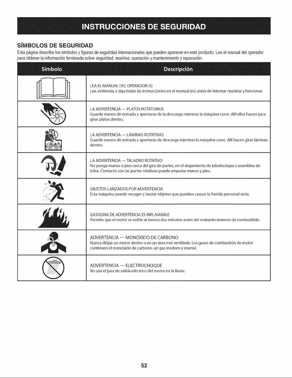
SiMBOLOS DE SEGURIDAD
Estap_ginadescribelossimbolosy figurasde seguridadinternacionalesque puedenaparecerenesteproducto.Lea el manualdel operador
)araobtenerla informaci6nterminadasobreseguridad,reunirse,operaci6ny mantenimientoy reparaci6n.
i
i
LEA EL MANUAL DEL OPERADOR (S)
Lea, entienda, y siga todas las instrucciones en el manual (es) antes de intentar reunirse y funcionar.
LA ADVERTENCIA -- PLATOS ROTATORIOS
Guarde manos de entrada y aperturas de la descarga mientras la m_iquina corre. Alli ellos hacen para
girar platos dentro.
LA ADVERTENCIA- LAMINAS ROTATIVAS
Guarde manos de entrada y aperturas de descarga mientras la m_iquina corre. Alli hacen girar I_iminas
dentro.
LA ADVERTENCIA -- TALADRO ROTATIVO
No ponga manos o pies cerca del giro de partes, en el alojamiento de taladro/aspa o asamblea de
tolva. Contacto con las partes rotativas puede amputar manos y pies.
OBJETOS LANZADOS POR ADVERTENCIA
Esta m_iquina puede recoger y lanzar objetos que pueden causar la herida personal seria.
GASOLINA DE ADVERTENCIA ESINFLAMABLE
Permita que el motor se enfrie al menos dos minutos antes del reabastecimiento de combustible.
ADVERTENCIA -- MONOXIDO DE CARBONO
Nunca dirijas un motor dentro o en un _irea mal ventilada. Los gases de combusti6n de motor
contienen el mon6xido de carbono, un gas inodoro y mortal.
ADVERTENCIA -- ELECTROCHOQUE
No use eljuez de salida el_ctrico del motor en la Iluvia.
52
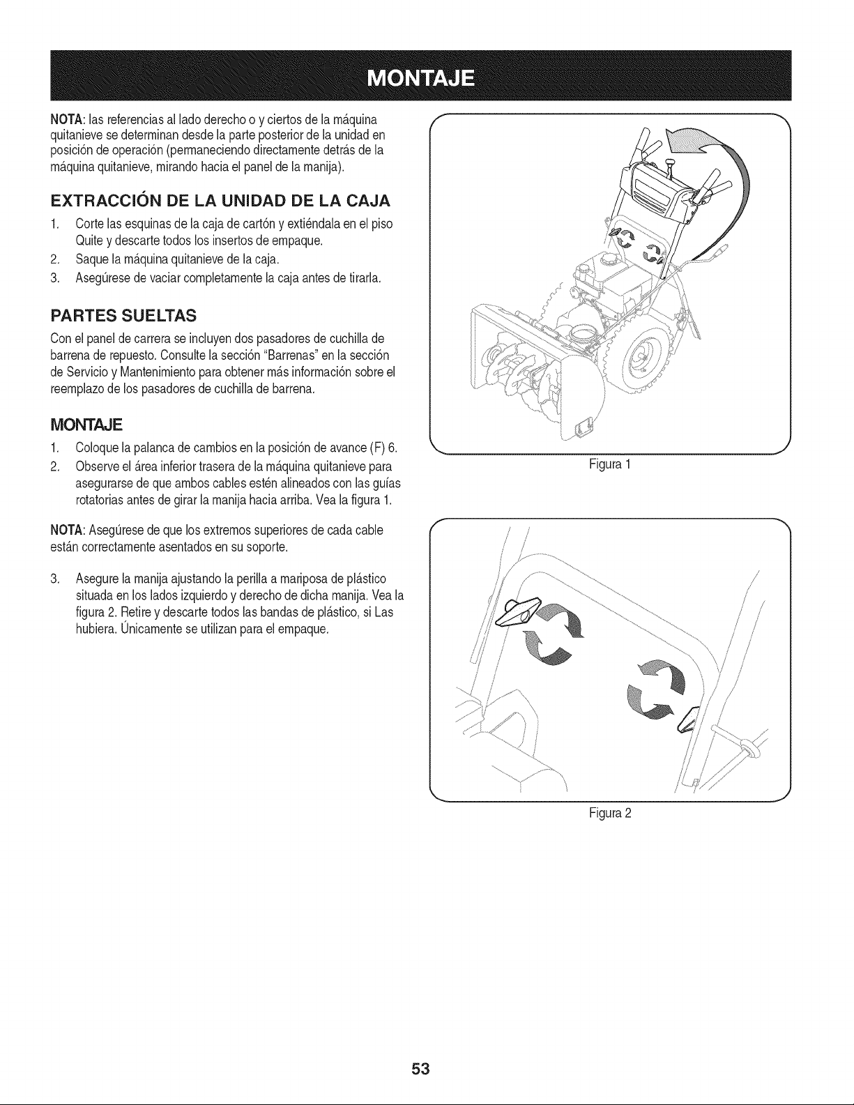
NOTA:las referenciasal ladoderechoo y ciertosde la m_.quina
quitanievesedeterminandesdela parteposteriorde la unidaden
posici6ndeoperaci6n(permaneciendodirectamentedetr_.sdela
m_.quinaquitanieve,mirandohaciael panelde lamanija).
EXTRACCI6N DE LA UNIDAD DE LA CAJA
1. Corte lasesquinasde la cajade cart6ny exti_ndalaenel piso
Quitey descartetodos los insertosde empaque.
2. Saquela m_.quinaquitanievede lacaja.
3. AsegQresede vaciarcompletamentela cajaantesdetirarla.
PARTES SUELTAS
Conel panelde carrerase incluyendos pasadoresde cuchillade
barrenade repuesto.Consultelasecci6n"Barrenas"en la secci6n
de Servicioy Mantenimientoparaobtenerm_.sinformaci6nsobreel
reemplazodelos pasadoresde cuchiNade barrena.
MONTAJE
,
2.
Coloquela palancade cambiosen la posici6ndeavance(F) 6.
Observeel _.reainferiortraserade la m_.quinaquitanievepara
asegurarsede queamboscablesest_nalineadoscon las gufas
rotatoriasantes de girar la manijahaciaarriba.Vea la figura1.
NOTA:AsegQresede quelosextremossuperioresde cadacable
est_.ncorrectamenteasentadosen susoporte.
,
Asegurela manijaajustandola perilla a mariposadepl_.stico
situadaen los ladosizquierdoy derechodedicha manija.Vea la
figura2. Retirey descartetodoslasbandasde pl_.stico,si Las
hubiera.Unicamentese utilizanparael empaque.
\
Figura1
f
Figura2
!
/
/
/
53
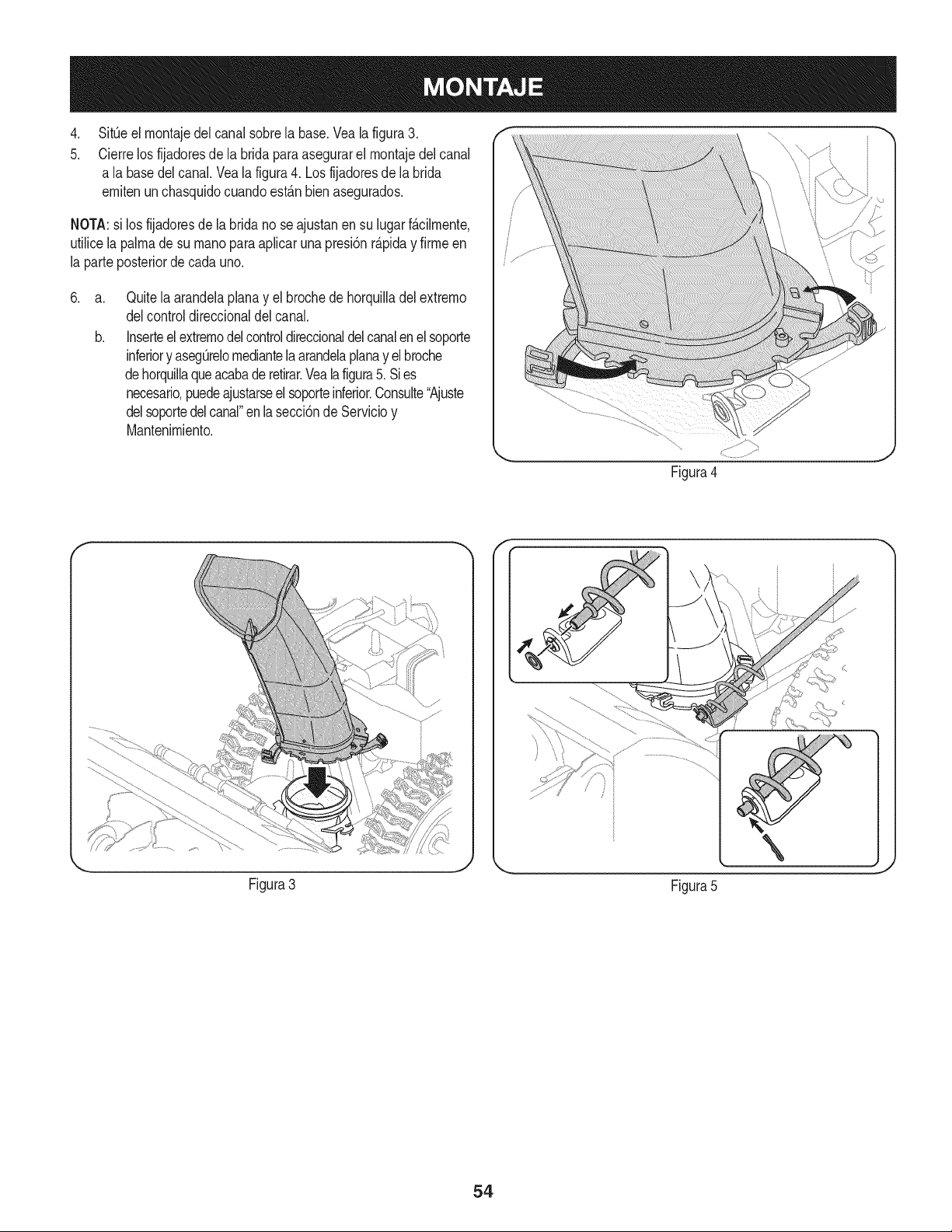
.
5.
SitOeel montajedel canalsobrela base.Vealafigura3.
Cierrelos fijadoresde la bridaparaasegurarel montajedelcanal
a la basedel canal. Veala figura4. Losfijadoresde labrida
emitenunchasquidocuandoest_.nbien asegurados.
NOTA:si los fijadoresde labridano seajustanen su lugarf_.cilmente,
utilicelapalmade su rnanopara apfcar unapresi6nr_.piday firmeen
la parteposteriorde cadauno.
.
a.
b.
Quitela arandelaplanay el brochede horquiladel extremo
delcontroldireccionaldel canal.
Inserteel extremodelcontroldireccionaldel canalenel soporte
inferiory asegOrelomediantela arandelaplanay elbroche
dehorquilaqueacabade retirar.Veala figura5. Sies
necesario,puedeajustarseelsoporteinferior.Consute"Ajuste
delsoportedelcanal"enlasecci6nde Servicioy
Mantenimiento.
Figura4
Figura3
Figura5
54
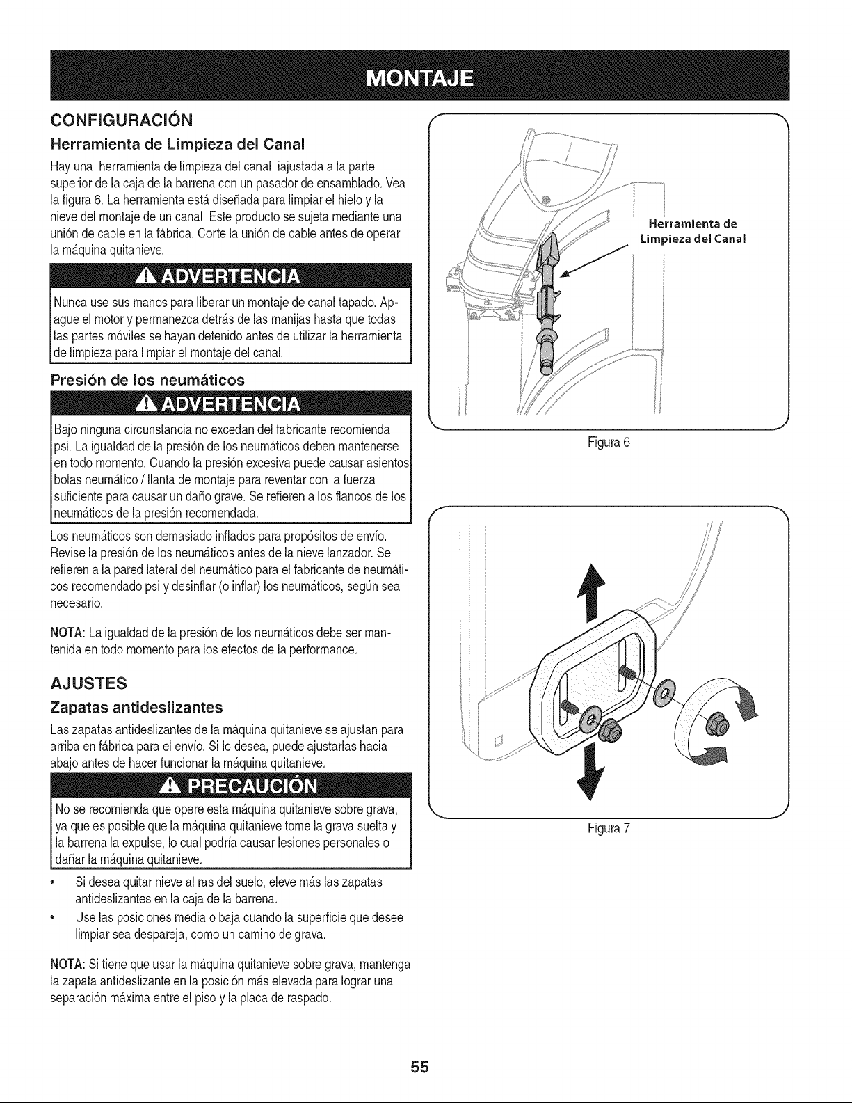
CONFIGURACION "_ "
Herramienta de Lirnpieza del Canal
Hayuna herrarnientade lirnpiezadel canal iajustadaa la parte
superiorde lacaja de la barrenacon un pasadorde ensarnNado.Vea
lafigura6. La herrarnientaest,.diseSadapara lirnpiarel hieloy la
nievedel rnontajede un canal.Este productose sujetarnedianteuna
uni6nde cableen laf_.brica.Corte la uni6n de cableantes de operar
la rnAquinaquitanieve.
Nuncausesus rnanosparaliberarunrnontajede canaltapado.Ap-
agueel motory perrnanezcadetr_.sde las rnanijashastaquetodas
las partes rn6vilesse hayandetenidoantesde utilizarla herrarnienta
de lirnpiezaparalirnpiarel rnontajedelcanal.
Presi6n de los neumaticos
Bajoningunacircunstancianoexcedandelfabricanterecornienda
psi.Laigualdaddela presi6nde los neurn_.ticosdebenrnantenerse
en todo rnornento.Cuandola presi6nexcesivapuedecausarasientos
bolasneurn_.tico/ Ilantadernontajepara reventarcon lafuerza
suficientepara causarunda_ograve.Serefierena los flancosde los
neurn_.ticosde lapresi6nrecornendada.
Los neurn_.ticosson dernasiadoinfiadospara prop6sitosde envio.
Revisela presi6nde los neurn_.ticosantesde la nievelanzador.Se
refierena la paredlateraldel neurn_.ticoparael fabricantede neurn_.ti-
cosrecornendadopsi y desinflar(o infiar)los neurn_.ticos,segQnsea
necesario.
NOTA:La igualdadde la presi6nde los neurn_.ticosdebeset man-
tenidaen todo rnornentoparalos efectosde la performance.
AJUSTES
Zapatas antideslizantes
Laszapatasantideslizantesde la rn_.quinaquitanieveseajustanpara
arribaen f_.bricaparaelenvio.Si Iodesea,puedeajustarlashacia
abajoantesdehacerfuncionarla rn_.quinaquitanieve.
No se recorniendaque opereesta rn_.quinaquitanievesobregrava,
ya que es posiblequela rn_.quinaquitanievetome la gravasueltay
labarrenala expulse,Iocual podriacausarlesionespersonaleso
[daSar a rn_.qunaqutan eve.
• Sideseaquitarnieveal rasdel suelo,elevern_.slaszapatas
antideslizantesen la cajade la barrena.
• Uselas posicionesmediao bajacuandola superficiequedesee
lirnpiarseadespareja,cornoun carninodegrava.
Herramienta de
Lira _iezadel Canal
Figura6
f
Figura7
NOTA:Si tienequeusar la rn_.quinaquitanievesobregrava,rnantenga
lazapataantideslizanteen la posici6nrn_.selevadaparaIograruna
separaci6nrn_.xirnaentreel pisoy laplacade raspado.
55
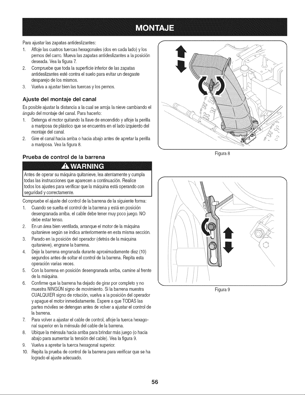
Paraajustarlas zapatasantideslizantes:
1. Aflojelascuatrostuercashexagonales(dos en cada lado)y los
pernosdel carro.Muevalas zapatasantideslizantesa laposici6n
deseada.Vea la figura 7.
2. Cornpruebequetoda la superficieinferiorde laszapatas
antideslizantesest_ contrael sueloparaevitar un desgaste
desparejode los rnisrnos.
3. Vuelvaa ajustarbienlas tuercasy los pernos.
Ajuste del montaje del canal
Es posibleajustarladistanciaa la cualse arroja la nievecarnbiandoel
_.ngulodel rnontajedelcanal.Parahacerlo:
1. Detengael motorquitandola Ilavedeencendidoy afioje la perilla
a rnariposade pl_.sticoque se encuentraen elladoizquierdodel
rnontajedel canal.
2. Gire el canal haciaarriba o haciaabajoantesdeapretarla perilla
a rnariposa.Vea la figura8.
Prueba de control de la barrena
Antesdeoperarsu rn_.quinaquitanieve,leaatentarnentey curnpla
todaslas instruccionesqueaparecena continuaci6n.Realice
todoslos ajustesparaverificarque la rn_.quinaest,.operandocon
seguridady correctarnente.
Cornpruebeel ajustedel controldela barrenade la siguienteforrna:
1. Cuandose sueltael controlde la barrenay est,.en posici6n
desengranadaarriba,el cabledebe tenetrnuypocojuego. NO
debeestartenso.
2. En un _.reabienventilada,arranqueel motorde larn_.quina
quitanievesegQnse indicaanteriorrnenteen esta rnisrnasecci6n.
3. Paradoen la posici6ndel operador(detr_.sde la rn_.quina
quitanieve),engranela barrena.
4. Dejela barrenaengranadaduranteaproxirnadarnentediez(10)
segundosantesde soltarel controlde la barrena.Repitaesta
operaci6nvariasveces.
5. Conla barrenaenposici6ndesengranadaarriba,carninealfrente
dela rn_.quina.
6. Confirrneque la barrenahadejadode girarporcornpletoy no
rnuestraNINGONsignode rnovirniento.Si labarrenarnuestra
CUALQUIERsignode rotaci6n,vuelvaa la posici6ndel operador
y apagueel motorinrnediatarnente.Esperea que TODASlas
partesrn6vilessedetenganantesde volvera ajustarel control de
la barrena.
7. Paravolvera ajustarel cabledecontrol,aflojela tuercahexago-
nalsuperioren la rn_nsuladelcablede la barrena.
8. Ubiquela rn_nsulahaciaarribapara brindarrn_.sjuego (o hacia
abajoparaaurnentarla tensi6ndelcable).Veala figura9.
9. Vuelvaa apretarla tuercahexagonalsuperior.
10. Repitala pruebadecontrolde la barrenaparaverificarque seha
Iogradoel ajuste adecuado.
Figura8
\
\
\
\
Figura 9
J
56
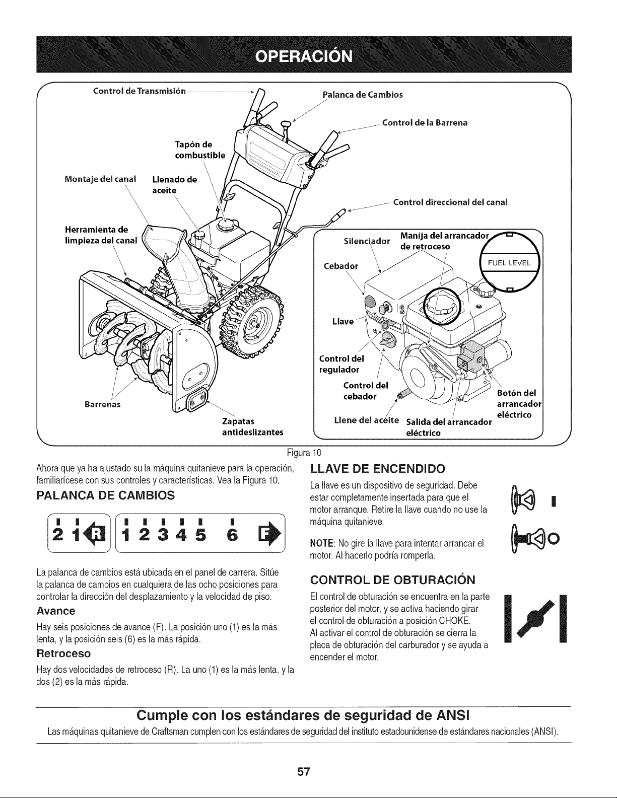
Control de Transmisi6n Palanca de Cambios
/
/
Controlde la Barrena
Tapbn de
combustible
\
IVlontajedel canal Llenado de
\_ aceite
\\
\
\
Herramienta de
limpieza del canal
\
\
\
Zapatas
antideslizantes
Control direccional del canal
. . Manija del arrancador
Sdenciaclor de retroceso
Cebador __
\
F
Control del
regulador
Control del \
cebador Botbn del
/ ! arrancador
_. el_ctrico
Llene clel acelte Salida del a rancador
J
Figura10
Ahoraqueya ha ajustadosu la rn_.quinaquitanieveparala operaci6n,
farniliaricesecon suscontrolesy caracteristicas.Veala Figura10.
PALANCA DE CAIVlBIOS
LLAVE DE ENCENDIDO
LaIlavees un dispositivode seguridad.Debe
estarcornpletarnenteinsertadapara que el
motorarranque.Retirela Ilavecuandono use la
rn_.quinaquitanieve.
NOTE: Nogire la Ilaveparaintentararrancarel
motor.AI hacerlopodriarornperh.
CONTROL DE OBTURACION
Elcontroldeobturaci6nse encuentraen la parte
posteriordelmotor,y seactiva haciendogirar
el controldeobturaci6na posici6nCHOKE•
AI activarel controlde obturaci6nse cierrala
placade obturaci6ndelcarburadory se ayudaa
encenderel motor.
I' '
21 12345 6
La palancadecarnbiosest,.ubicadaen el panelde carrera.SitQe
la palancadecarnbiosen cualquierade las ochoposicionespara
controlarladirecci6ndel desplazarnientoy lavelocidadde piso.
Avance
Hayseisposicionesde avance(F). Laposici6nuno(1)es larn_.s
lenta,y la posici6nseis(6) es la rn_.sr_.pida.
Retroceso
Haydosvelocidadesde retroceso(R). Launo(1)es la rn_.slenta,y la
dos (2) es la rn_.sr_.pida.
J
Curnple con los estandares de seguridad de ANSi
Lasrn&quinasquitanievedeCraftsmancurnplenconlosest&ndaresde seguridaddelinstitutoestadounidensede est&ndaresnacionales(ANSI).
57
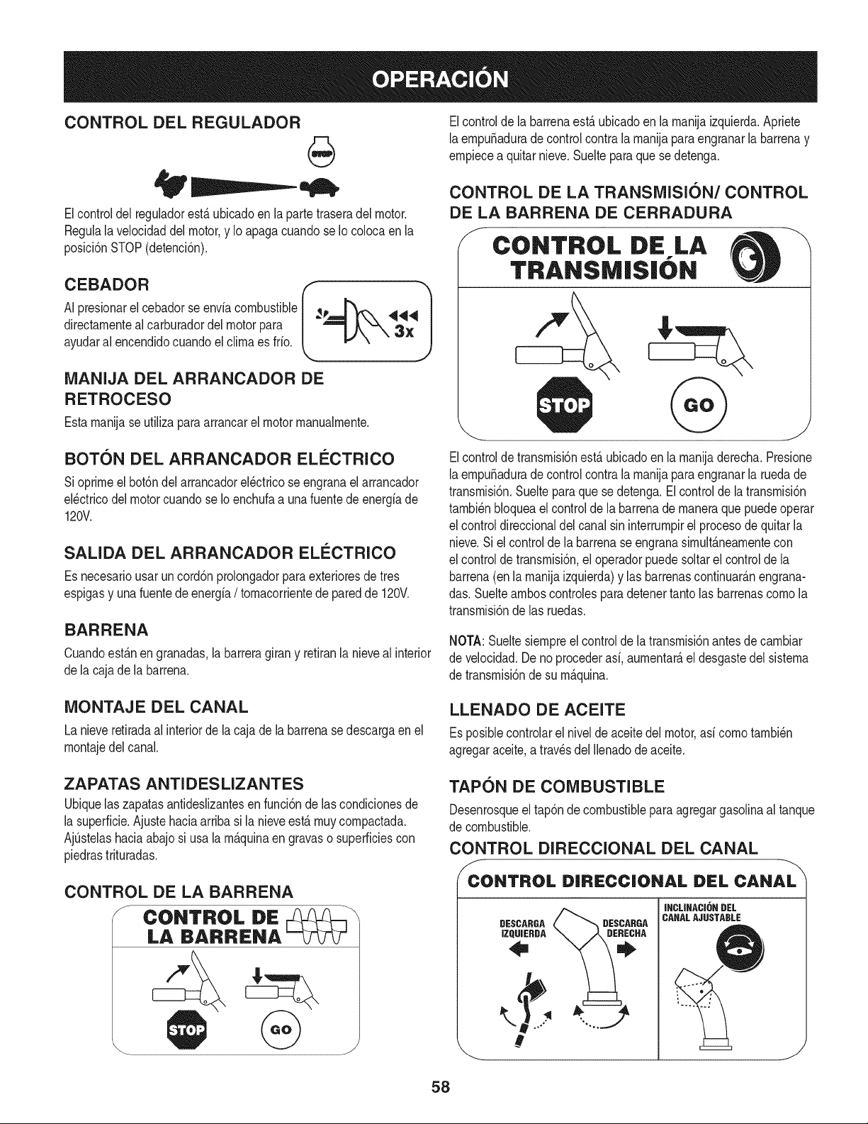
CONTROL DEL REGULADOR
Elcontrol del regulador estfi ubicado en la parte trasera del motor.
Negula la velocidad del motor, y Io apaga cuando se Iocoloca en la
posicidn STOP (detencidn).
A1pEeBsioAnDartlcRebadorseenvlacombustible_p -.._
directamentealcarburadordel motor para r- _ ._4 |
ayudara, encendidocuandoel climaes frio. _ _,,/\ \,XJ
MANIJA DEL ARRANCADOR DE
RETROCESO
Estamanijase utilizaparaarrancarel motormanualmente.
BOTON DEL ARRANCADOR ELI_CTRICO
Sioprimeel bot6ndelarrancadorel_ctricose engranael arrancador
el_ctricodel motorcuandose Ioenchufaa unafuentedeenergiade
120V.
SALIDA DEL ARRANCADOR ELI_CTRICO
Es necesariousar uncord6nprolongadorparaexterioresde tres
espigasy una fuentede energia/ tomacorrientede paredde 120V.
BARRENA
Cuandoest_.nen granadas,la barreragirany retiranla nievealinterior
dela cajade la barrena.
Elcontrolde labarrenaest,.ubicadoen la manijaizquierda.Apriete
laempuSadurade controlcontra la manijapara engranarla barrenay
empiecea quitarnieve.Suelteparaquese detenga.
CONTROL DE LA TRANSMISION/CONTROL
DE LA BARRENA DE CERRADURA
S CONTROL DiE LA --\
TRANSM|S|ON
Elcontroldetransmisi6nest,.ubicadoen la manijaderecha.Presione
laempuSadurade controlcontra la manijapara engranarla ruedade
transmisi6n.Sueltepara que se detenga.El controldela transmisi6n
tambi_nbloqueael controldela barrenade maneraque puedeoperar
el controldireccionaldel canalsin interrumpirel procesodequitarla
nieve.Si el controlde la barrenase engranasimult_.neamentecon
el controlde transmisi6n,el operadorpuedesoltarel controlde la
barrena(en la manijaizquierda)y las barrenascontinuar_.nengrana-
das.Suelteamboscontrolesparadetenertantolas barrenascomo la
transmisi6nde las ruedas.
NOTA:Sueltesiempreel controlde latransmisi6nantesde cambiar
de velocidad.Deno procederasi, aumentar_,eldesgastedel sistema
de transmisi6nde su m_.quina.
MONTAJE DEL CANAL
La nieveretiradaal interiorde la cajade la barrenase descargaen el
montajedel canal.
LLENADO DE ACEITE
Esposiblecontrolarel nivelde aceitedelmotor,asi como tambi_n
agregaraceite,a travesdel Ilenadodeaceite.
ZAPATAS ANTI DES LIZANTES
Ubiquelas zapatasantideslizantesen funci6nde lascondicionesde
la superficie.Ajustehaciaarribasi la nieveest,. muy compactada.
AjOstelashaciaabajosi usala m_.quinaengravaso superficiescon
piedrastrituradas.
TAPON DE COMBUSTIBLE
Desenrosqueel tap6nde combustibleparaagregargasolinaal tanque
de combustible.
CONTROL DIRECCIONAL DEL CANAL
f
CONTROL DIRECC|ONAL DEL CANAL
DESCARGA
IZQUIERDA
DESCARGA
INCLINACI6N DEL
CANALAJUSTABLE
J
58
Paracarnbiarla direcci6nhaciala cual se arrojala nieve,gire el
controldireccionaldel canal.
HERRAMIENTA DE LllVlPIEZA
Nuncause sus rnanosparaliberarunrnontajedecanaltapado.Antes
de destaparlo,apagueel motory perrnanezcadetr_.sde las rnanijas I
_hastaquetodas as partesrn6v es se hayandetendo. j
La herrarnientadelirnpiezadel canalest,. ajustadaconvenienternente
a la parteposteriorde lacaja de la barrenaconun pasadordeensarn-
blado.Si se acurnulannievey hieloen elcanalde descargadurante
laoperaci6n,procedacornose indicaa continuaci6nparalirnpiarde
rnanerasegurael rnontajedelcanaly laaberturadelcanal:
1. Suelteel controlde la barrenay elcontrolde latransrnisi6n.
2. Paradetenerel motorsaquela Ilavedeencendido.
3. Saquela herrarnientade lirnpiezadel pasadorque laajustaa la
parteposteriorde la cajade la barrena.
4. Use el extrernocon forrnade palade laherrarnientade lirnpieza
paradesplazary recogerla nievey el hieloquese forrnaroncerca
delconjuntodelcanal.
5. Vuelvaa ajustarla herrarnientade lirnpiezaal pasadordeen-
sarnbladoubicadoen la parteposteriorde lacaja de labarrena,
insertede nuevola Ilavedeencendidoy enciendael motorde la
rn_.quinaquitanieve.
6. Paradoen la posici6ndel operador(detr_.sdelarn_.quinaquita-
nieve),engraneelcontroldelabarrenaduranteunossegundospara
elirninarlanieveo el hieloquehayanquedadoen el conjuntodel
canal.
ANTES DE ENCENDER EL MOTOR
Lea,cornprenday siga todaslas instruccionesy advertenciasque
aparecenen la rn_.quinayen este manualantesdeoperarla.
Aceite
El motor seenvi6con aceite en el motor.Controleel nivelde
aceiteantesde cadaoperaci6npara asegurarsede quehayaaceite
suficienteen el motor.Paraobtenerrn_.sinstrucciones,rernitasea los
pasosqueaparecenen lap_.gina52.
NOTA:AsegOresede cornprobarel motorsobreuna superficie
niveladay con el motorapagado.
1. Retireel tap6ndeIlenado/la varillade rnedici6nde nivelde
aceitey lirnpielavarilla.
2. Inserteel tap6n/la varilladernedici6nen el cuellodeIlenadode
aceite,pero no laatornille.
3. Extraigael tap6nde Ilenado/ lavarillade nivelde aceite.Si
el niveles bajo,agregueaceite (5W-30,con unaclasificaci6n
minimade SF/SG)lentarnentehastaqueel registromarqueentre
nivelalto (H) y bajo(L).
NOTA:No Io Ileneen exceso.ElIlenadoexcesivodeaceitepuede
hacerque el motorgenerehurno,que cuestearrancarloo fallasenla
bujia.
4. Vuelvaa colocarel tap6n/la varillade aceitey ajusteconfirrneza
antesdearrancarel motor.
Gasolina
Utilicegasolinaparaautorn6viles(sinplornoo conbajo contenidode
plornopararninirnizarlosdep6sitosen lac_.rnarade cornbusti6n)con
un octanajerninirnode 87.Se puede usargasolinacon hastaun 10%
de etanolo un 15%de MTBE(eterrnefilicoterciario-bufilico).Nunca
use una rnezclade aceitey gasolinanigasolinasucia.Evitequese
introduzcasuciedad,polvoo aguaenel tanquedecombustible.NO
utilicegasolinaE85.
• Carguecombustibleen un_.reabien ventiladay con el motor
apagado.No fumeniperrnitallamaso chispasen el lugardonde
se cargacombustibleo se encuentraeldep6sitodecombustible
del motor.
• NoIleneen excesoel tanquedecombustible.Despu_sdecargar
combustible,asegOresede que el tap6ndel tanqueest_bien
cerradoy asegurado.
• Tengacuidadode no derrarnarcombustibleal realizarla recarga.
Elcombustiblederrarnadoo susvaporesse puedenincendiar.
Si se derrarnacombustible,asegQresede queel _.reaest_seca
antesdearrancarel motor.
• Eviteel contactorepetidoo prolongadocon la piel o inhalarlos
vapores.
Tengaextrernocuidadocuandornanipulegasolina.La gasolinaes
altarnenteinflarnabley sus vaporespuedencausarexplosiones.
Nuncaagreguecombustiblea la rn_.quinaen interioreso rnientras
lel motorest,.calienteo en funcionarniento.Apaguelos cigarrillos,
_cigarros,pipasy otrasfuentesde cornbusti6n.
1. Antesde sacarlatapa paracargarcombustible,lirnpiealrededor.
2. Enel tanquede combustiblehay unindicadorde nivel. Lleneel
tanquehasta Ilegaral nivelde combustibledel indicador.Veala
Figura10.Tengacuidadoparano Ilenarel dep6sitoenexceso.
ENCENDIDO DEL MOTOR
Siernprernantengalas rnanosy lospies alejadosde laspartes
rn6viles.Noutilice fluidoscornprirnidosparaarrancar.Losvapores
son infiarnables.
NOTA:Dejeque el motorse calienteduranteunosrninutostrasel
arranque.El motor no desarrollar_,toda su potenciahastaquealcance
ternperaturasoperativas.
1. AsegOresede que elcontrolde la barrenay el controlde la
transrnisi6nest_nen posici6ndesengranada(sin presionar).
2. Insertela Ilaveenla ranura.AsegQresedequeentrea presi6nen
su lugar.No intentegirar la Ilave.
NOTA: El motorno puedearrancarsi la Ilaveno est,.cornpletarnente
insertadaenel interruptordeencendido.
59
Arrancador el_ctrico
Elarrancadorel_ctricoopcionalest&equipadocon uncable de ali-
rnentaci6ny unenchufedetresterrninalesconectadosa tierray est,.
dise_adoparaoperarcon corrientedorn_sticade 120voltios.Debe
setutilizadocon un recept_.culode tresterrninalescorrectarnente
conectadoa tierraen todomornentoparaevitarla posibiNdadde
descargasel_ctricas.Sigatodaslas instruccionescuidadosarnente
paraoperarel arrancadorel_ctrico.NOutiliceel arrancadorel_ctrico
bajolaIluvia.
Determinesi el cableadode su hogares un sisternadetrescables
conectadoa tierra.Consultecon unelectricistarnatriculadosi noest,.
seguro.
Sicuentaconun recept_.culodetresterrninales,siga lossiguientes
pasos.Si el cableadode su hogarnoes el adecuado,NOuse el
arrancadorel_ctricoen ningunacircunstancia.
1. Conecteel prolongadora la salidasituadaenla superficiedel
motor.Conecteel ottoextrernodel prolongadoren unrecept_.culo
deCA conconexi6na tierrade tres terrninalesde 120voltios,en
un_.reabien ventilada.
2. Muevala palancade controldel reguladora laposici6nFAST
(r_.pido,representadapor unaliebre)._1
3. Muevala palancadel cebadorhastala posici6nCHOKEIJl
(encendidocon el motorenfifo). Siel motorya est,.caliente,
ubiqueel cebadoren laposici6nOFR
4. Presioneel cebadortres (3)veces,asegur_.ndosede cubrirel
orificiode ventilaci6ncuandoIohaga.Si el motorest,.caliente,
presioneel cebadoruna solavez.Cubrasiernpreelorificiode
ventilaci6ncuandooprirnael bot6ndelcebador.Si hacefifo
puederesultarnecesariorepetirel cebado.
5. Presioneel bot6ndel arrancadorparaarrancarel motor.Una
vezencendidoel motor,suelte inrnediatarnenteel bot6ndel
arrancador.Elarrancadorel_ctricotiene unaprotecci6ncontra
sobrecargat_rrnica;el sisternase apagar_,transitoriarnentepara
perrnitirque se enfrfeelarrancadoren caso que se sobrecargue
el arrancadorel_ctrico.
6. Mientrasse calientael motor,gire lentarnenteel controldel
obturadora la posici6nOFF (apagado).Si el motorse detiene,
vuelvaa encenderlo,h_.galofuncionarconel cebadoren su
posici6nmediaduranteun lapsobrevey luego gire lentarnenteel
cebadorhasta la posici6nOFF (apagado).
7. Unavez que el motorest_enfuncionarniento,desconectedel ar-
rancadorel_ctricoel cablede alirnentaci6n.Paradesconectarlo,
desenchufesiernpreel extrernoque est,. enchufadoal tornacor-
rientede paredantes de desenchufarel extrernoopuestoque
est,,conectadoal motor.
Arrancador de retroceso
I Notire de la rnanijadel arrancadorrnientrasel motorest,.en rnarcha.I
1. Muevala palancade controldel reguladora laposici6nFAST
(r_.pido,representadapor unaliebre'_ ).
2. Muevala palancadelcebadorhastala posici6nCHOKEI,'q¢l
(encendidoconel motoren fifo). Si el motorya est,.caliente,
ubiqueel cebadoren la posici6nOFR
3. Presioneel cebadortres(3) veces,asegur_.ndosedecubrirel
orificiodeventilaci6ncuandoIo haga.Siel motorest,.caliente,
presioneel cebadoruna solavez.Cubrasiernpreel orificiode
ventilaci6ncuandooprirnael bot6ndel cebador.Si hacefifo
puederesultarnecesariorepetirel cebado.
4. Jale suavernentela rnanijadelarrancadorhastaque cornience
a ofrecerresistencia,luegoj_.lelar_.pidarnentey con fuerzapara
superarla cornpresi6n.No sueltela rnanijani perrnitaque se
desenganche.VuelvalacuerdaLENTAMENTEa su posici6n
original.Deset necesario,repitaeste paso.
5. Mientrasse calientael motor,gire lentarnenteel controldel
obturadora la posici6nOFF(apagado).Siel motorse detiene,
vuelvaa encenderlo,h_.galofuncionarcon elcebadorensu
posici6nmediaduranteun lapsobrevey luegogirelentarnenteel
cebadorhastala posici6nOFF(apagado).
Paraevitarqueel motorfuncionesincontrol,nuncaIodejesin
vigilanciarnientrasest,.en rnarcha.Apagueel motorluegode usarlo
y saquela Nave.
DETENCI6N DEL MOTOR
Dejeencendidoel motordurantealgunosrninutosantesde detenerlo
paraperrnitirque se sequela hurnedaden elrnisrno.
1. Muevael controldel reguladora la posici6nOFR
2. RetirelaIlave.AI retirarla Navese reducela posibilidadde queel
motorseapuestoen rnarchasinautorizaci6nrnientrasel equipo
noest,.enuso.Guardela Naveen un lugarseguro.Elmotorno
puedearrancarsin laIlave.
3. Elirninelahurnedadde loscontrolesdel motor.
PROCEDIMIENTO PARA ENGRANAR LA
TRANSMISI6N
1. Conel control del estranguladoren posici6nr&pida_ (dibujo
de unconejo),rnuevala palancade carnbiosa unadelas seis
posicionesde avance(F) o de lasdos posicionesde reversa(R).
Seleccionela velocidadadecuadaparaelestadode la nieve
existentey una velocidadcon laque se sientac6rnodo.
2. Aprieteel controldela transrnisi6ncontrala rnanijaderecha,y la
rn_.quinaquitanievese rnover_..Su_lteloy sedetendr_,el
rnovirnientodela transrnisi6n.
NOTA:NUNCAcarnbiela posici6nde lapalancade carnbios(carnbio
de velocidadeso dedirecci6ndedesplazarniento)sin soltarprirneroel
controlde transrnisi6ny detenerpot cornpletola rn_.quinaquitanieve.
Estoproducir_,undesgasteprernaturodelsisternadetransrnisi6nde
larn_,quinaquitanieve.
PROCEDIMIENTO PARA ENGRANAR LAS
BARRENAS
1. Aprieteel control de la barrenacontrala rnanijay lasbarrenas
rotar_.n.Su_ltelay lasbarrenasse detendr_.n.
6O
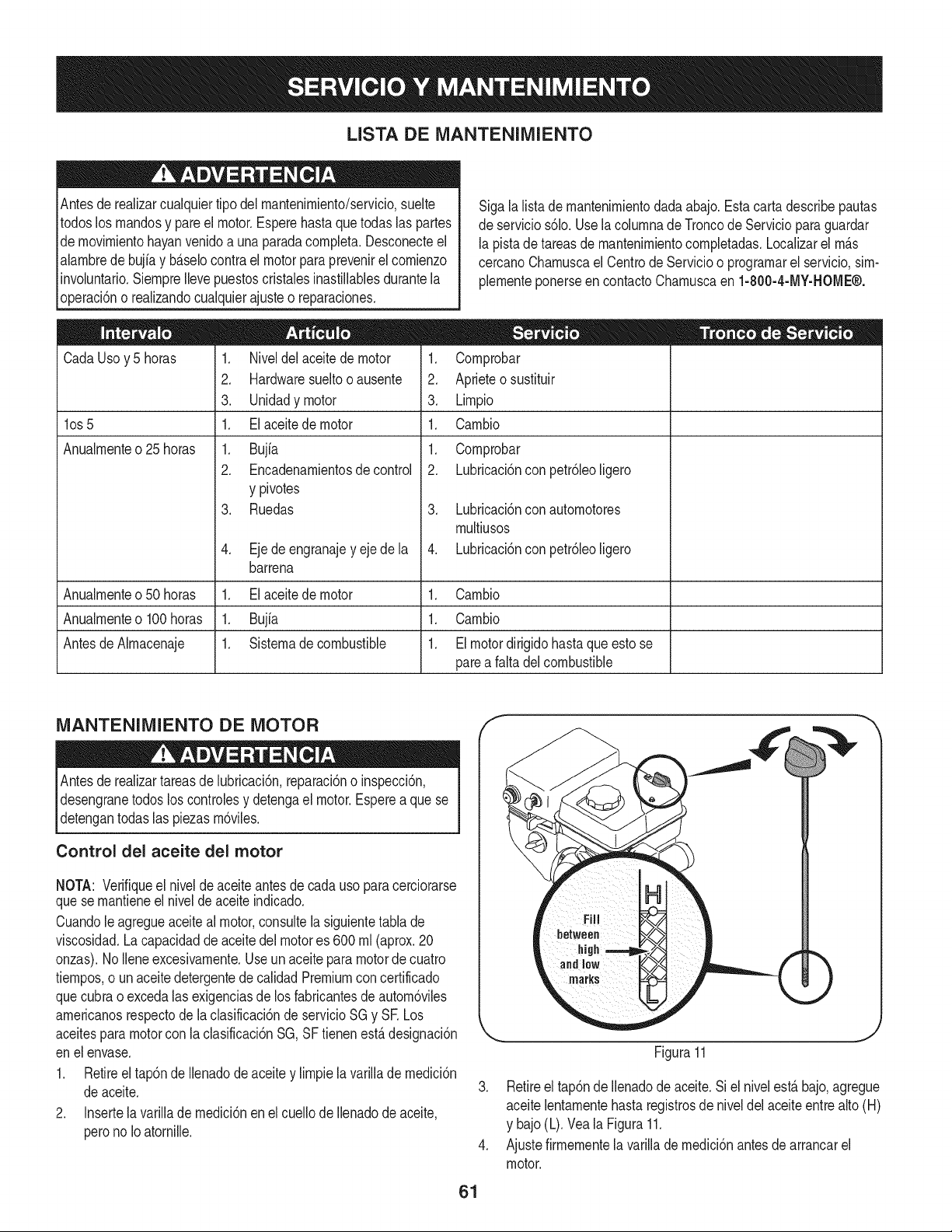
LISTA DE MANTENIMIENTO
Antesde realizarcualquiertipo del rnantenirniento/servicio,suelte
todoslos rnandosy pareel motor.Esperehastaquetodaslas partes
de rnovirnientohayanvenidoa unaparadacornpleta.Desconecteel
alarnbredebujiay b_.selocontrael motorparaprevenirel cornienzo
involuntario.SiernpreIlevepuestoscristalesinastillablesdurantela
operaci6no realizandocualquierajusteo reparaciones.
CadaUsoy 5 horas
los 5
Anualrnente o 25 horas
1. Niveldel aceitede motor
2. Hardwaresueltooausente
3. Unidadymotor
1. El aceite de motor
1. Bujfa
2. Encadenarnientosde control
y pivotes
3. Ruedas
4. Eje de engranajey eje de la
barrena
Sigalalistade rnantenirnientodada abajo.Estacarta describepautas
de servicios61o.Usela colurnnade Troncode Servicioparaguardar
la pistade tareasde rnantenirnientocornpletadas.Localizarel rn_.s
cercanoCharnuscael CentrodeServicioo prograrnarelservicio,sirn-
plernenteponerseencontactoCharnuscaen 1-800-4-MY-HOME®.
1. Cornprobar
2. Aprieteo sustituir
3. Lirnpio
1. Carnbio
1. Cornprobar
2. Lubricaci6nconpetr61eoligero
3. Lubricaci6nconautornotores
rnultiusos
4. Lubricaci6nconpetr61eoligero
Anualrnenteo50 horas 1. Elaceitede motor 1. Carnbio
Anualrnenteo100horas 1. Bujia 1. Carnbio
AntesdeAlrnacenaje 1. Sisternade combustible 1. El motordirigidohasta que esto se
parea faltadelcombustible
MANTENIMIENTO DE MOTOR
Antes lubricaci6n,reparaci6no inspecci6n,
de realizartareasde
desengranetodos los controlesy detengael motor.Esperea que se
detengantodas las piezasrn6viles.
Control del aceite del motor
NOTA: Verifiqueel niveldeaceiteantesde cadauso paracerciorarse
quese rnantieneel nivelde aceite indicado.
Cuandole agregueaceiteal motor,consultela siguientetabla de
viscosidad.La capacidadde aceitedel motores 600 rnl (aprox.20
onzas).NoIleneexcesivarnente.Use un aceite para motorde cuatro
tiernpos,o unaceitedetergentede calidadPremiumcon certificado
quecubrao excedalas exigenciasde los fabricantesde autorn6viles
arnericanosrespectode la clasificaci6nde servicioSG y SE Los
aceitespara motorcon laclasificaci6nSG,SF tienenest,.designaci6n
enel envase.
1. Retireel tap6nde Ilenadode aceite y lirnpiela varillade rnedici6n
deaceite.
2. Insertela varilladernedici6nenel cuellodeIlenadode aceite,
perono Ioatornille.
f
61
Figura11
J
3. Retireel tap6nde Ilenadode aceite.Si el nivelest,.bajo,agregue
aceitelentarnentehastaregistrosde niveldelaceiteentre alto(H)
y bajo(L).Vea la Figura11.
4. Ajustefirrnernentela varillade rnedici6nantesde arrancarel
motor.
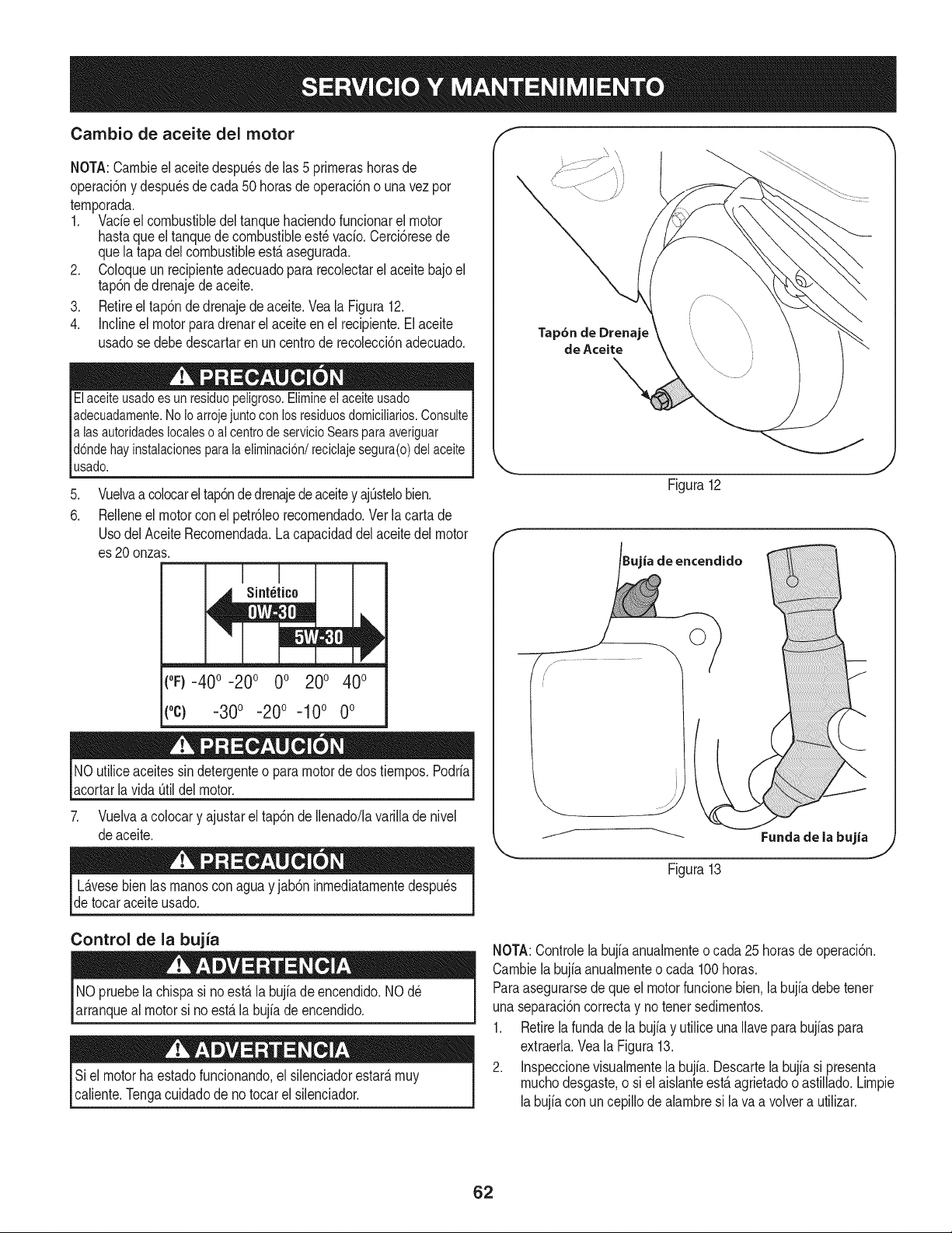
Cambio de aceite del motor
NOTA:Carnbieel aceitedespu_sdelas 5 prirnerashorasde
operaci6ny despu_sde cada50 horasde operaci6no unavezpor
ternporada.
1. Vacfeel combustibledeltanquehaciendofuncionarel motor
hastaqueel tanquedecombustibleest_vacfo.Cerci6resede
quela tapadelcombustibleest,.asegurada.
2. Coloqueun recipienteadecuadopara recolectarel aceitebajo el
tap6nde drenajede aceite.
3. Retireel tap6ndedrenajedeaceite.Vea la Figura12.
4. Inclineel motorparadrenarelaceiteenel recipiente.Elaceite
usadose debedescartaren uncentrode recolecci6nadecuado.
Elaceite usado es un residuopeligroso. Elimineel aceiteusado
adecuadamente.No Io arrojejunto con los residuosdomicilMos. Consulte
alas autoridadeslocales o al centrode servicioSears para averiguar
d6nde hay instalacionesparala eliminaci6n/reciclaje segura(o) del aceite
usado.
.
6.
Vuelvaa colocarel tap6nde drenajedeaceitey ajOstelobien.
Relleneel motorcon el petr61eorecornendado.Ver la carta de
UsodelAceiteRecornendada.La capacidaddel aceitedel motor
es 20 onzas.
t°F)-40 o-20 o 0o 200 400
(oc) -30o -20o -10o 0o
NOutiliceaceitessindetergenteo paramotordedos tiernpos.Podrfa
acortarlavida Otildel motor.
7. Vuelvaa colocary ajustarel tap6nde Ilenado/lavarillade nivel
deaceite.
Tap6n de Drenaje
de Aceite
Figura12
ia de encendido
j._ .....................
Fundade la bujia
Figura13
L_.vesebien las rnanosconagua y jab6ninrnediatarnentedespu_s
de tocaraceiteusado.
Control de la bujia
NOpruebela chispasi noest,.la bujfade encendido.NO d_
arranqueal motorsi no est,.labujfade encendido.
Siel motorhaestadofuncionando,elsilenciadorestar_,rnuy
caliente.Tengacuidadode notocarel silenciador.
NOTA:Controlela bujb anualrnenteo cada 25horasde operaci6n.
Carnbiela bujb anualrnenteo cada 100horas.
Paraasegurarsede queel motorfuncionebien.la bujfadebetenet
unaseparaci6ncorrectay no tenet sedirnentos.
1. Retirela fundade la bujb y utilice unaIlavepara bujbs para
extraerla.Vea la Figura13.
2. Inspeccionevisualrnentela bujfa. Descartela bujb si presenta
rnuchodesgaste,o siel aisianteest,.agrietadoo astillado.Lirnpie
labujb con un cepillode abrnbre si lava a volvera utilizar.
62
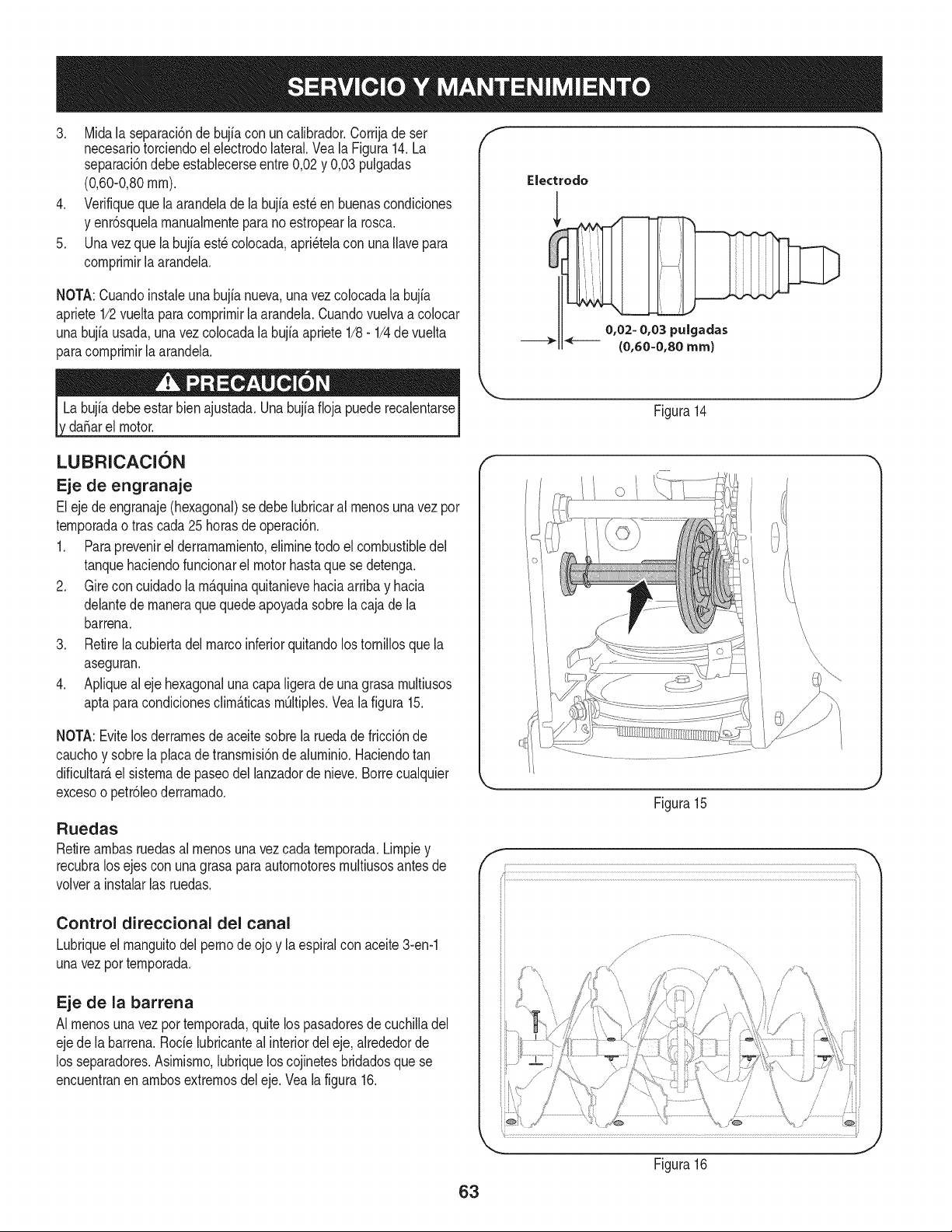
3. Midala separaci6ndebujiacon un calibrador.Corrijade ser
necesariotorciendoel electrodolateral.Veala Figura14.La
separaci6ndebeestablecerseentre0,02y 0,03 pulgadas
(0,60-0,80ram).
4. Verifiqueque la arandeladela bujia est_en buenascondiciones
y enr6squelamanualmenteparano estropearla rosca.
5. Unavez que la bujfaest_colocada,apri_telacon una Ilavepara
comprimirla arandela.
NOTA:Cuandoinstaieunabujianueva,unavezcolocadala bujia
apriete1/2vuelta paracomprimirlaarandela.Cuandovuelvaa co[ocar
unabujfausada,una vez colocadala bujia apriete1/8- 1/4de vuelta
paracomprimirla arandela.
da_arel motor.
f
Electrodo
0,02= 0,03 puigadas
(0,60=0,80 ram)
Figura14
LUBRICACION
Eje de engranaje
Eleje deengranaje(hexagonal)se debelubricaral menosunavezpor
temporadao tras cada25 horasde operaci6n.
1. Paraprevenirel derramamiento,eliminetodo el combustibledel
tanquehaciendofuncionarel motorhastaquese detenga.
2. Gire concuidadola m_.quinaquitanievehaciaarribay hacia
delantede maneraque quedeapoyadasobrela cajade la
barrena.
3. Retirela cubiertadelmarcoinferiorquitandolos tornillosquela
aseguran.
4. Apliqueal eje hexagonaluna capaligera de una grasa multiusos
aptapara condicionesclim_.ticasm_ltiples.Vea la figura 15.
NOTA:Evitelos derramesdeaceitesobrela ruedadefricci6nde
cauchoy sobrela placade transmisi6nde aluminio.Haciendotan
dificultar_,el sistemade paseodel lanzadordenieve.Borrecualquier
excesoo petr61eoderramado.
Ruedas
Retireambasruedasal menosunavezcada temporada.Limpiey
recubralos ejescon unagrasaparaautomotoresmultiusosantesde
volvera instalarlas ruedas.
Control direccional del canal
Lubriqueel manguitodel pernodeojo y la espiralcon aceite3-en-1
unavezportemporada.
Eje de la barrena
AI menosuna vez por temporada,quitelos pasadoresde cuchilladel
ejede labarrena.Rode lubricanteal interiordel eje,alrededorde
los separadores.Asimismo,lubriquelos cojinetesbridadosque se
encuentranen ambosextremosdel eje.Vea la figura 16.
Figura15
63
Figura16
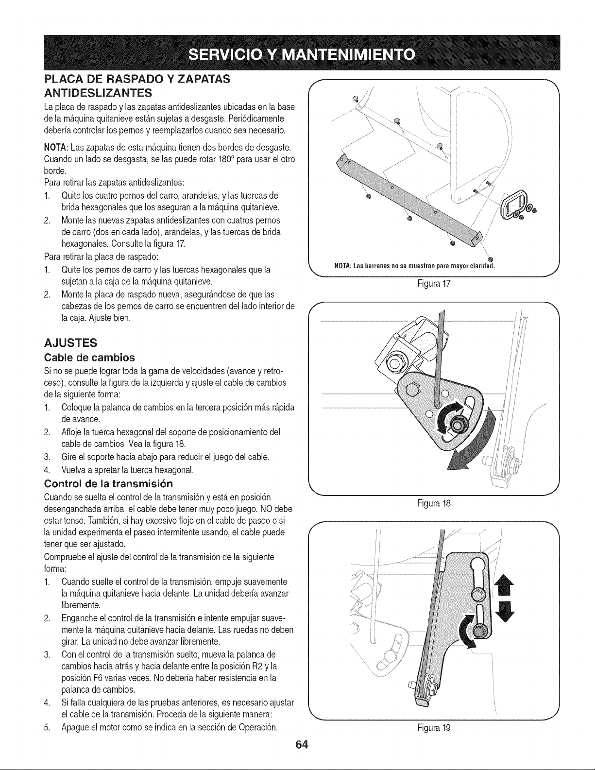
PLACA DE RASPADO Y ZAPATAS
ANTIDESLIZANTES
La placade raspadoy laszapatasantideslizantesubicadasen labase
dela rn_.quinaquitanieveest_.nsujetasa desgaste.Peri6dicarnente
deberiacontrolarlospernosy reernplazarloscuandosea necesario.
NOTA:Laszapatasde esta rn_.quinatienendos bordesdedesgaste.
Cuandoun ladose desgasta,se las puederotar 1800para usarel otro
horde.
Pararetirarlas zapatasantideslizantes:
1. Quitelos cuatropernosdel carro,arandelas,y las tuercasde
bridahexagonalesque los asegurana la rn_.quinaquitanieve.
2. Montelas nuevaszapatasantideslizantescon cuatrospernos
decarro (dosen cada lado),arandelas,y las tuercasde brida
hexagonales.Consultela figura17.
Pararetirarla placade raspado:
1. Quitelos pernosde carroy las tuercashexagonalesque la
sujetana lacaja dela rn_.quinaquitanieve.
2. Montela placade raspadonueva,asegur_.ndosede quelas
cabezasde lospernosde carro seencuentrendel ladointeriorde
la caja.Ajustebien.
AJUSTES
Cable de cambios
Si nose puedeIogrartodala garnade velocidades(avancey retro-
ceso),consultela figurade la izquierday ajusteel cablede carnbios
dela siguienteforrna:
1. Coloquela palancadecarnbiosenla terceraposici6nrn_.sr_.pida
deavance.
2. Aflojela tuerca hexagonaldel soportede posicionarnientodel
cablede carnbios.Vealafigura 18.
3. Gire el soportehaciaabajo para reducirel juegodel cable.
4. Vuelvaa apretarla tuercahexagonal.
Control de la transmisi6n
Cuandose sueltael controlde la transrnisi6ny est&en posici6n
desenganchadaarriba,el cabledebetenor rnuypocojuego. NOdebe
estartenso.Tarnbi_n,si hay excesivoflojoen elcable de paseoo si
la unidadexperirnentael paseointerrnitenteusando,elcable puede
tenorque ser ajustado.
Cornpruebeel ajustedel controldela transrnisi6nde la siguiente
forrna:
1. Cuandosuelteel controlde la transrnisi6n,ernpujesuavernente
la rn_.quinaquitanievehaciadelante.La unidaddeberia avanzar
librernente.
2. Engancheel controlde latransrnisi6ne intenteernpujarsuave-
montela rn_.quinaquitanievehaciadelante.Las ruedasno deben
girar.La unidadnodebeavanzarlibrernente.
3. Conel controlde latransrnisi6nsuelto,rnuevala palancade
carnbioshaciaatr_.sy haciadelanteentre la posici6nR2 y la
posici6nF6varias veces.Nodeberia haber resistenciaen la
palancade carnbios.
4. Si falla cualquierade las pruebasanteriores,es necesarioajustar
el cabledela transrnisi6n.Procedadela siguienternanera:
5. Apagueel motor cornose indicaen la secci6nde Operaci6n.
/'
\
,\
NOTA:Las barreoas no se muestraa para mayor ¢laridad.
Figura17
//
/
f
.........ii
Figura18
Figura19
.J
64
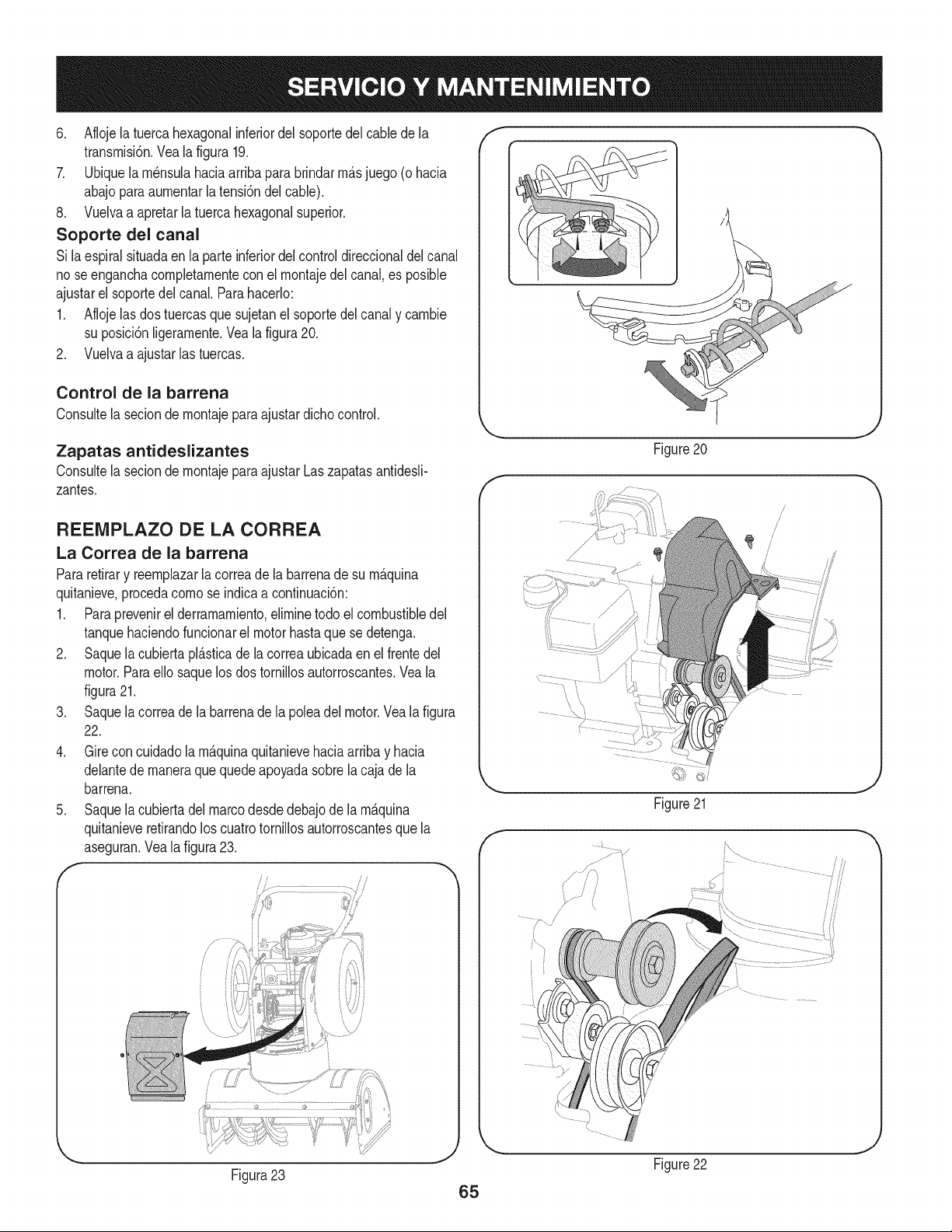
6. Aflojela tuerca hexagonalinferiordel soportedelcablede la
transmisi6n,Veala figura 19,
7. Ubiquela m6nsulahaciaarribapara brindarm_.sjuego (o hacia
abajoparaaumentarla tensi6ndelcable).
8, Vuelvaa apretarla tuercahexagonalsuperior,
Soporte del canal
Si laespiralsituadaenla parteinferiordel controldireccionaldel canal
no seenganchacompletamenteconel montajedelcanal,es posible
ajustarel soportedelcanal,Parahacerlo:
1. Aflojelas dostuercasque sujetanel soportedel canaly cambie
su posici6nligeramente.Vealafigura20.
2. Vuelvaa ajustarlas tuercas.
Control de la barrena
Consultela seciondemontajeparaajustardichocontrol.
Zapatas antideslizantes
Consultela seciondemontajeparaajustarLaszapatasantidesli-
zantes.
REEIVIPLAZO DE LA CORREA
La Correa de la barrena
Pararetirary reemplazarla correade la barrenade su m_.quina
quitanieve,procedacomose indicaa confinuaci6n:
1. Paraprevenirel derramamiento,eliminetodo el combustibledel
tanquehaciendofuncionarel motorhastaquese detenga.
2. Saquela cubiertapl_.sticade lacorreaubicadaen el frentedel
motor.Paraello saquelos dos tornillosautorroscantes.Veala
figura21.
3. Saquela correade la barrenade la poleadel motor.Vealafigura
22.
4. Gire concuidadola m_.quinaquitanievehaciaarribay hacia
delantede maneraque quedeapoyadasobrela cajade la
barrena.
5. Saquela cubiertadelmarcodesdedebajode la m_.quina
quitanieveretirandoloscuatrotornillosautorroscantesque la
aseguran.Veala figura23.
f
f
Figure20
/
J
Figure21
J
Figure22
Figura23
65
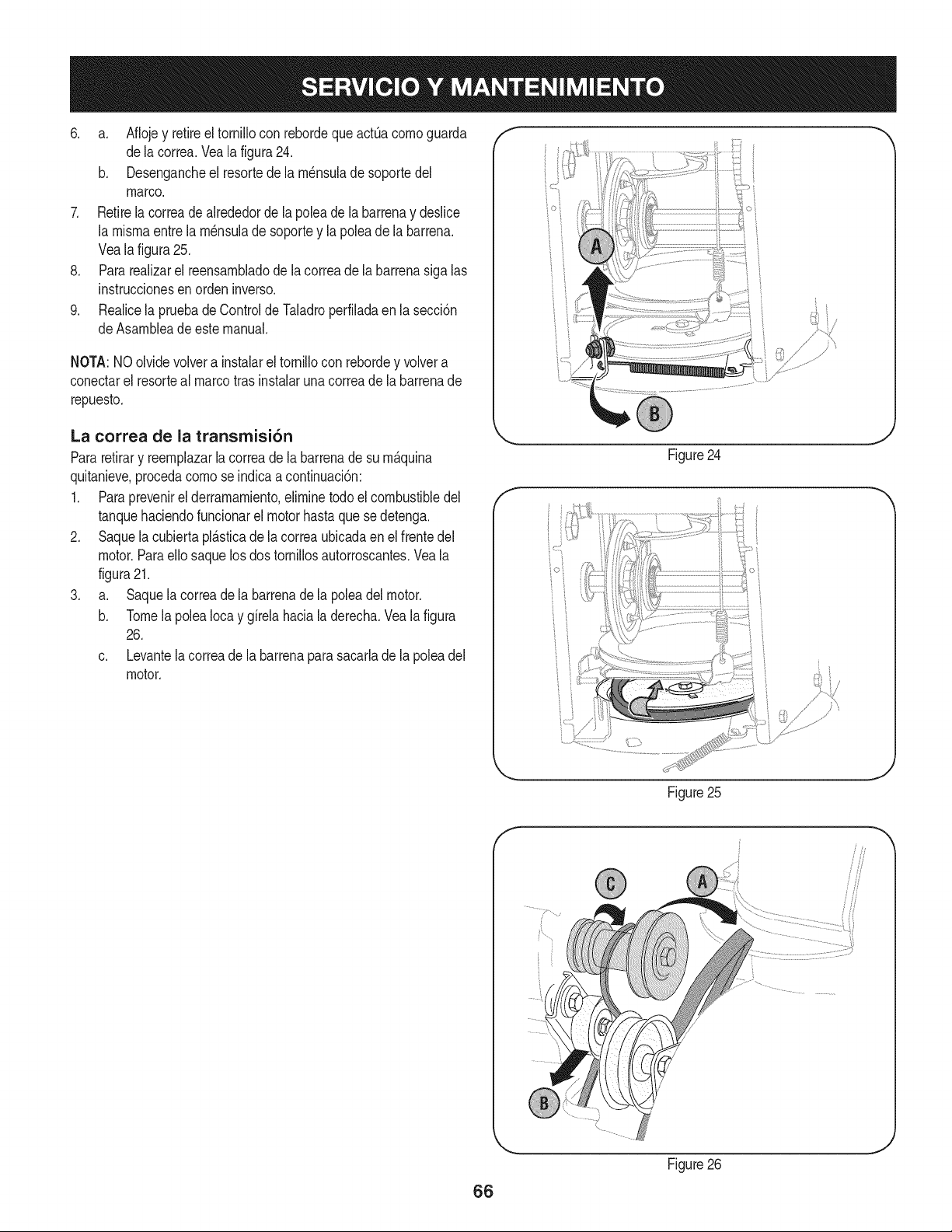
6. a. Aflojey retireel tornillocon rebordeque actOacomoguarda
dela correa.Vealafigura24.
b. Desengancheel resortede la m_nsulade soportedel
marco.
7. Retirela correade alrededorde la poleade la barrenay deslice
la mismaentre la m_nsulade soportey la polea de la barrena.
Vealafigura25.
8. Pararealizarel reensambladode lacorreade labarrenasiga las
instruccionesen orden inverso.
9. Realicela pruebadeControldeTaladroperfiladaen lasecci6n
deAsambleadeestemanual.
NOTA:NOolvidevolvera instalarel tornillocon rebordey volvera
conectarel resorteal marcotrasinstalarunacorreade la barrenade
repuesto.
La correa de la transmisi6n
Pararetirary reemplazarla correadela barrenade su m&quina
quitanieve,procedacomose indicaacontinuaci6n:
1. Para prevenirel derramamiento,eliminetodoel combustibledel
tanquehaciendofuncionarel motorhastaque sedetenga.
2. Saquela cubiertapl_.sticade lacorreaubicadaen el frentedel
motor.Paraello saquelosdos tornillosautorroscantes.Veala
figura21.
3. a. Saquela correade la barrenade la poleadelmotor.
b. Tomela polea Iocay girela haciala derecha.Vea la figura
26.
c. Levantela correade la barrenaparasacarlade lapoleadel
motor.
f
/" }
Figure24
t j
Figure25
66
f
9
Figure26
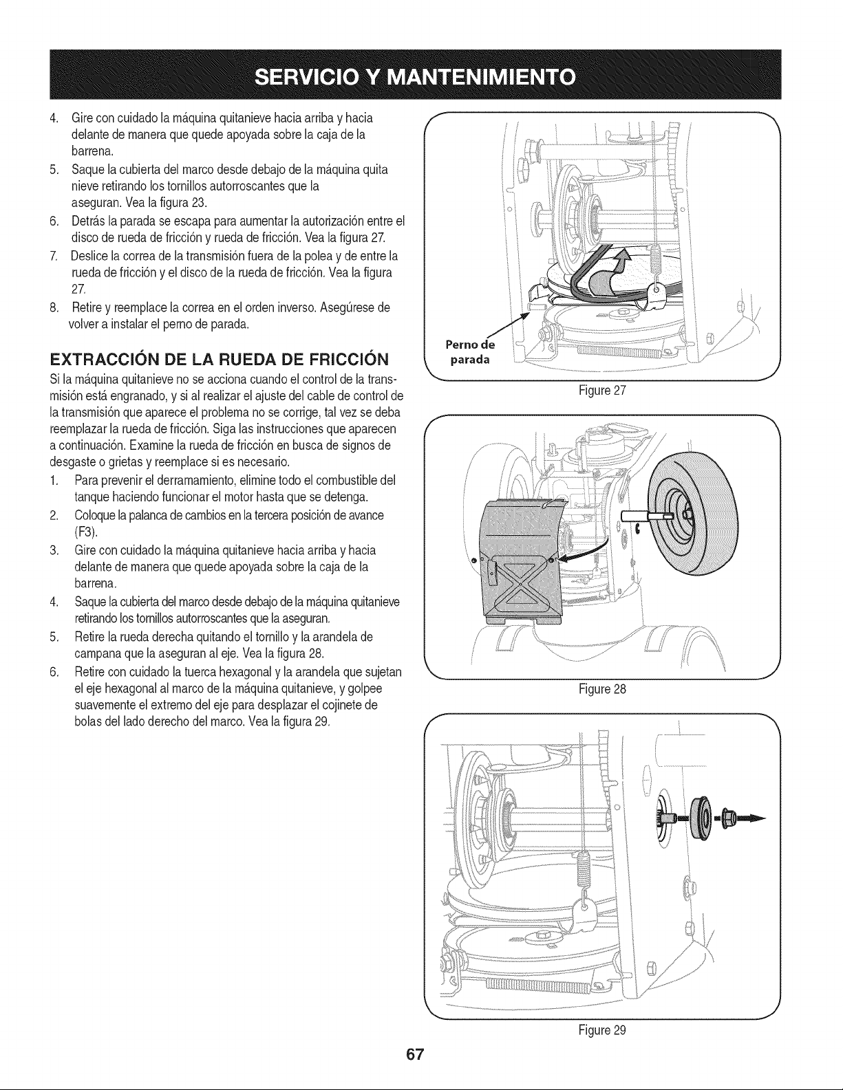
4. Gireconcuidadolarn_.quinaquitanievehaciaarribayhacia
delantedernaneraquequedeapoyadasobrelacajadela
barrena.
5. Saquelacubiertadelmarcodesdedebajodelarn_.quinaquita
nieveretirandolostorniNosautorroscantesquela
aseguran.Vealafigura23.
6. Detr_.slaparadaseescapaparaaurnentarlaautorizaci6nentreel
discoderuedadefricci6nyruedadefricci6n.Vealafigura27.
7. Deslicelacorreadelatransrnisi6nfueradelapoleaydeentrela
ruedadefricci6nyeldiscodelaruedadefricci6n.Vealafigura
27.
8. Retireyreernplacelacorreaenelordeninverso.Asegt]resede
volverainstalarelpernodeparada.
EXTRACCI6N DE LA RUEDA DE FRICCI6N
Si larn&quinaquitanievenose accionacuandoel controlde la trans-
rnisi6nest,. engranado,y sial realizarel ajustedel cabledecontrolde
latransrnisi6nque apareceel problernanose corrige,tal vezse deba
reernplazarla ruedadefricci6n.Sigalas instruccionesqueaparecen
acontinuaci6n.Examinela ruedade fricci6nen buscade signosde
desgasteo grietas y reernplacesi es necesario.
1. Paraprevenirel derrarnarniento,elirninetodo elcombustibledel
tanquehaciendofuncionarel motorhastaquese detenga.
2. Coloquelapalancadecarnbiosenlaterceraposici6nde avance
(F3).
3. Gire concuidadola rn_.quinaquitanievehaciaarribay hacia
delantede rnaneraque quedeapoyadasobrela cajade la
barrena.
4. Saquela cubiertadel marcodesdedebajode la rn_.quinaquitanieve
retirandolostornillosautorroscantesquelaaseguran.
5. Retirela ruedaderechaquitandoel tornilloy la arandelade
carnpanaque la aseguranal eje. Veala figura28.
6. Retirecon cuidadola tuercahexagonaly la arandelaque sujetan
eleje hexagonalal marcode la rn_.quinaquitanieve,y golpee
suavernenteel extrernodel ejeparadesplazarel cojinetede
bolasdel ladoderechodel marco.Vea la figura29.
Perno de
parada
f
Figure27
/ ii
Figure28
J
Figure29
J
67
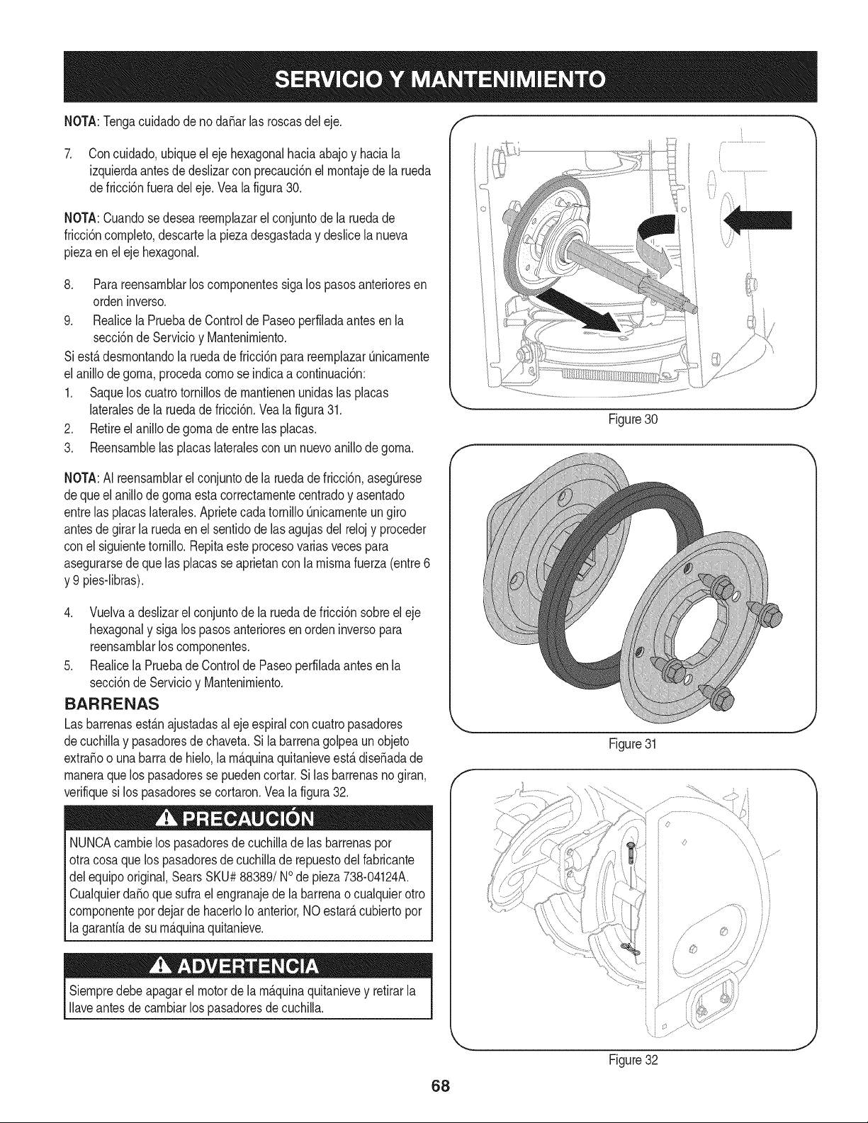
NOTA:Tengacuidadode no daSarlas roscasdel eje. f
7. Concuidado,ubiqueel ejehexagonalhaciaabajoy haciala
izquierdaantesde deslizarcon precauci6nel rnontajede la rueda
defricci6nfueradel eje.Vealafigura30.
NOTA:Cuandosedesea reernplazarel conjuntode la ruedade
fricci6ncornpleto,descartela piezadesgastaday deslicela nueva
piezaen el ejehexagonal.
8. Parareensarnblarlos cornponentessiga lospasosanterioresen
ordeninverso.
9. Realicela Pruebade Controlde Paseoperfiladaantes en la
secci6nde Servicioy Mantenirniento.
Siest,.desrnontandola ruedadefricci6n parareernplazarOnicarnente
el anillodegorna,procedacornose indicaa continuaci6n:
1. Saquelos cuatrotornillosdernantienenunidaslas placas
lateralesde la ruedade fricci6n.Vea la figura31.
2. Retireel anillode gornadeentrelas placas.
3. Reensarnblelas placaslateralescon unnuevoanillo de gorna.
Figure30
J
NOTA:AI reensarnblarel conjuntode la ruedade fricci6n,asegOrese
dequeel anillode gornaesta correctarnentecentradoy asentado
entrelas placaslaterales.AprietecadatornilloQnicarnenteungiro
antesde girarla ruedaen el sentidode lasagujasdel relojy proceder
conel siguientetornillo.Repitaeste procesovariasvecespara
asegurarsede quelas placasse aprietancon la rnisrnafuerza(entre6
y 9 pies-libras).
4. Vuelvaa deslizarelconjuntodela ruedade fricci6nsobreel eje
hexagonaly sigalos pasosanterioresen ordeninversopara
reensarnblarloscornponentes.
5. Realicela Pruebade Controlde Paseoperfiladaantesen la
secci6nde Servicioy Mantenirniento.
BARRENAS
Las barrenasest_.najustadasal eje espiralcon cuatropasadores
decuchillay pasadoresde chaveta.Sila barrenagolpea un objeto
extraSoo unabarrade hielo,la rn_.quinaquitanieveest,.diseSadade
rnaneraque los pasadoresse puedencortar.Si las barrenasno giran,
verifiquesi los pasadoresse cortaron.Veala figura32.
NUNCAcarnbielos pasadoresde cuchillade las barrenaspor
otracosa que lospasadoresdecuchillade repuestodel fabricante
delequipooriginal,SearsSKU#88389/NOde pieza738-04124A.
CualquierdaSoque sufra el engranajede la barrenao cualquierotro
cornponentepordejardehacerloIoanterior,NOestarAcubiertopor
la garantiade su rn_.quinaquitanieve.
Siernpredebeapagarel motorde la rn_.quinaquitanievey retirarla
Ilaveantesde carnbiarlos pasadoresde cuchilla.
Figure31
Figure32
J
68
Sinosevaa utilizael equipodurante30 dfaso rn_.s,o sies el finaldelaternporadadenievey ya noexisteposibilidaddequenieve,es necesario
alrnacenarel equipode rnaneraadecuada.Sigalasinstruccionesde alrnacenarnientoquese indicanacontinuaci6nparagarantizarel rendirniento
rn_.xirnodelarn_.quinaquitanieveduranternuchosa_os.
PREPARACI6N DEL MOTOR
Losrnotoresque se alrnacenandurantern&sde 30 dfasnecesitan
serdrenadosdecombustibleparaevitarquese deterioreny se forrne
gornaenel sisternade combustibleo en las piezasprincipalesdel
carburador.Si lagasoNnade su motorse deterioraduranteel alrnace-
narniento,es posiblequedeba repararo reernplazarelcarburadory
otroscornponentesdel sisternade combustible.
1. Elirninetodoel combustibledel tanquehaciendofuncionarel
motorhastaquese detenga.No intentede combustibleparael
motor.
2. Carnbieel aceitedel motor.
3. Extraigala bujfade encendidoy viertaen elcilindroaproxirna-
darnente1 onza(30 rnl)de aceiteparamotorNrnpio.Tire varias
vecesdel arrancadorde retrocesopara distribuirel aceite y
reinstalela bujfa.
4. Lirnpielos residuosde alrededordel motor,y debajo,alrededor,
y detr_.sdel silenciador.ApNqueunacapa delgadade aceiteen
todaslas _.reasque puedenNegara oxidarse.
• Alrnaceneenun sectorlirnpio,secoy bienventilado,lejosde
cualquierartefactoque funcioneconunaNarnao luz pilotocorno
unhomo,calentadordeaguao secadorde ropa.Evitecualquier
sectorcon un motorel_ctricoqueproduzcachispaso dondese
utilicenherrarnientasel_ctricas.
Nuncaalrnacenela rn_.quinaquitanieveconcombustibleen el
tanqueen un espaciocerradooen _.reascon pocaventilaci6n,
dondelosgases del combustiblepuedanalcanzarel fuego,chispas
o unaluz pilotocornola quetienenalgunoshornos,calentadoresde
agua,secadoresde ropao algQnotto dispositivoagas.
PREPARACION DE LA iVlAQUINA QUITANIEVE
1. Cuandoalrnacenela rn&quinaquitanieveen ungalp6nde
dep6sitornet_.licoo con pocaventilaci6n,tengaespecialcuidado
de realizarleuntratarnientoanti- oxidanteal equipo.Useaceite
ligeroo silic6npararecubrirel equipo,especialrnentelas
cadenas,los resortes,loscojinetesy loscables.
2. Elirninetodo el polvodelexteriordelmotory delequipo.
3. Siga las recornendacionesde lubricaci6nen la secci6nde
mantenirnientode este manual.
4. Alrnaceneel equipoen un_.readespejaday seca.
• Si es posible,evitesectoresdealrnacenarnientocon rnucha
hurnedad.
• Mantengael motorniveladoen el alrnac_n.Lainclinaci6ndel
motorpuedecausarperdidasde combustibleo aceite.
69
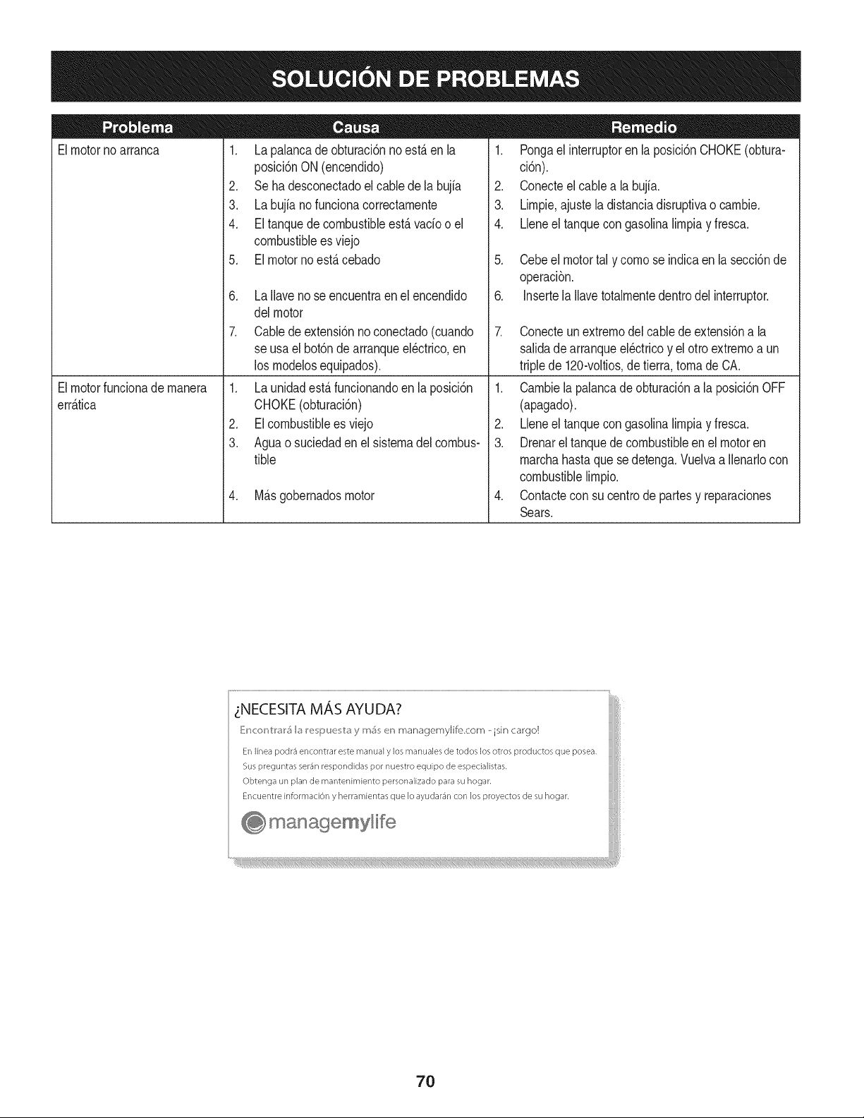
Elmotornoarranca
1. La palancade obturaci6nno est,. en la
posici6nON (encendido)
2. Se ha desconectadoelcablede la bujia
3. La bujianofuncionacorrectamente
4. El tanquede combustibleest,. vado o el
combustibleesviejo
5. El motornoest,.cebado
6. La Ilavenose encuentraen el encendido
delmotor
7. Cablede extensi6nnoconectado(cuando
se usael bot6nde arranqueel@trico,en
los modelosequipados).
1. Pongael interruptoren la posici6nCHOKE(obtura-
ci6n).
2. Conecteel cablea la bujfa.
3. Limpie,ajustela distanciadisruptivao cambie.
4. Lleneel tanquecongasolinalimpiay fresca.
5. Cebeel motortal y comose indicaen lasecci6nde
operaci6n.
6. Insertela Ilavetotalmentedentrodelinterruptor.
7. Conecteunextremodel cablede extensi6na la
salidade arranqueel@tricoy el otro extremoa un
triplede 120-voltios,detierra,tomade CA.
Elmotorfuncionademanera
err_.tica
1. La unidadest,.funcionandoen laposici6n
CHOKE(obturaci6n)
2. EIcombustibleesviejo
3. Aguao suciedadenel sistemadel combus-
tible
4. M_.sgobernadosmotor
1. Cambiela palancade obturaci6na la posici6nOFF
(apagado).
2. Lbne el tanquecongasolinalimpiay fresca.
3. Drenarel tanquedecombustibleenel motoren
marchahastaque sedetenga.Vuelvaa Ilenarlocon
combustiblelimpio.
4. Contactecon su centrode partesy reparaciones
Sears.
zNECESITA MAS AYUDA?
_!ncor_V:r_r5 b I_e i_uu v:_y m_ en managemylife.com _ isin cargo!
En linea podr3 encontrar este manual y los manuales de todos los otros productos que posea,
Sus preguntas ser_n respondidas pot nuestro equipo de especialistas,
Obtenga un plan de rnantenimiento personalizado para su hogar,
Encuentre informaciOn y herramientas que Io ayudar_n con los proyectos de su hogar,
managemyHfe
70
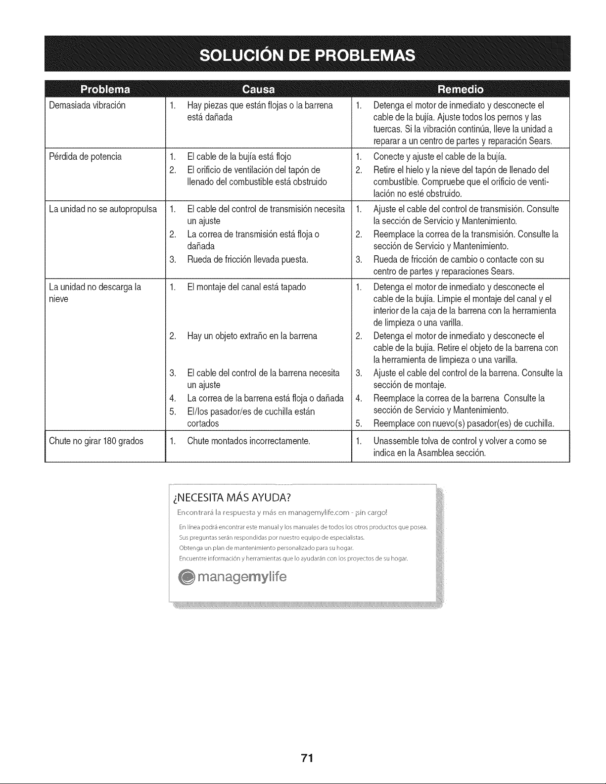
Dernasiadavibraci6n
1. Hay piezasque est_.nfiojaso la barrena
est,.dafiada
1. El cable dela bujfaest,. flojo
2. El orificio de ventilaci6ndel tap6nde
Ilenadodel combustibleest,. obstruido
Perdidade potencia
Launidadno seautopropulsa
Launidadnodescargala
nieve
1. El cable delcontroldetransrnisi6nnecesita
unajuste
2. La correade transrnisi6nest,. floja o
da_ada
3. Ruedade fricci6nIlevadapuesta.
1. El rnontajedelcanalest,.tapado
2. Hay un objetoextra_oen la barrena
3. El cable delcontrolde la barrenanecesita
unajuste
4. La correade labarrenaest,.flojao da_ada
5. El/los pasador/esdecuchillaest_.n
cortados
1. Detengael motorde inrnediatoy desconecteel
cablede la bujia.Ajustetodoslos pernosy las
tuercas.Sila vibraci6ncontinQa.Ilevela unidada
reparara uncentrode partesy reparaci6nSears.
1. Conectey ajusteel cablede la bujfa.
2. Retireel hieloy la nievedel tap6nde Ilenadodel
combustible.Cornpruebequeel orificiode venti-
laci6nno est_ obstruido.
1. Ajusteel cabledelcontrolde transrnisi6n.Consulte
la secci6nde Servicioy Mantenirniento.
2. Reernplacela correade latransrnisi6n.Consultela
secci6nde Servicioy Mantenirniento.
3. Ruedade fricci6ndecarnbioo contacteconsu
centrode partesy reparacionesSears.
1. Detengael motorde inrnediatoy desconecteel
cablede la bujia.Lirnpieel rnontajedel canaly el
interiorde la cajade labarrenacon laherrarnienta
de lirnpiezao unavarilla.
2. Detengael motorde inrnediatoy desconecteel
cablede la bujia.Retireel objetode la barrenacon
la herrarnientade lirnpiezao unavarilla.
3. Ajusteel cabledelcontrolde la barrena.Consultela
secci6nde rnontaje.
4. Reernplacela correade la barrena Consultela
secci6nde Servicioy Mantenirniento.
5. Reernplacecon nuevo(s)pasador(es)de cuchilla.
Chutenogirar180grados 1. Chuternontadosincorrectarnente. 1. Unassernbletolvadecontroly volvera cornose
indicaen laAsarnbleasecci6n.
71
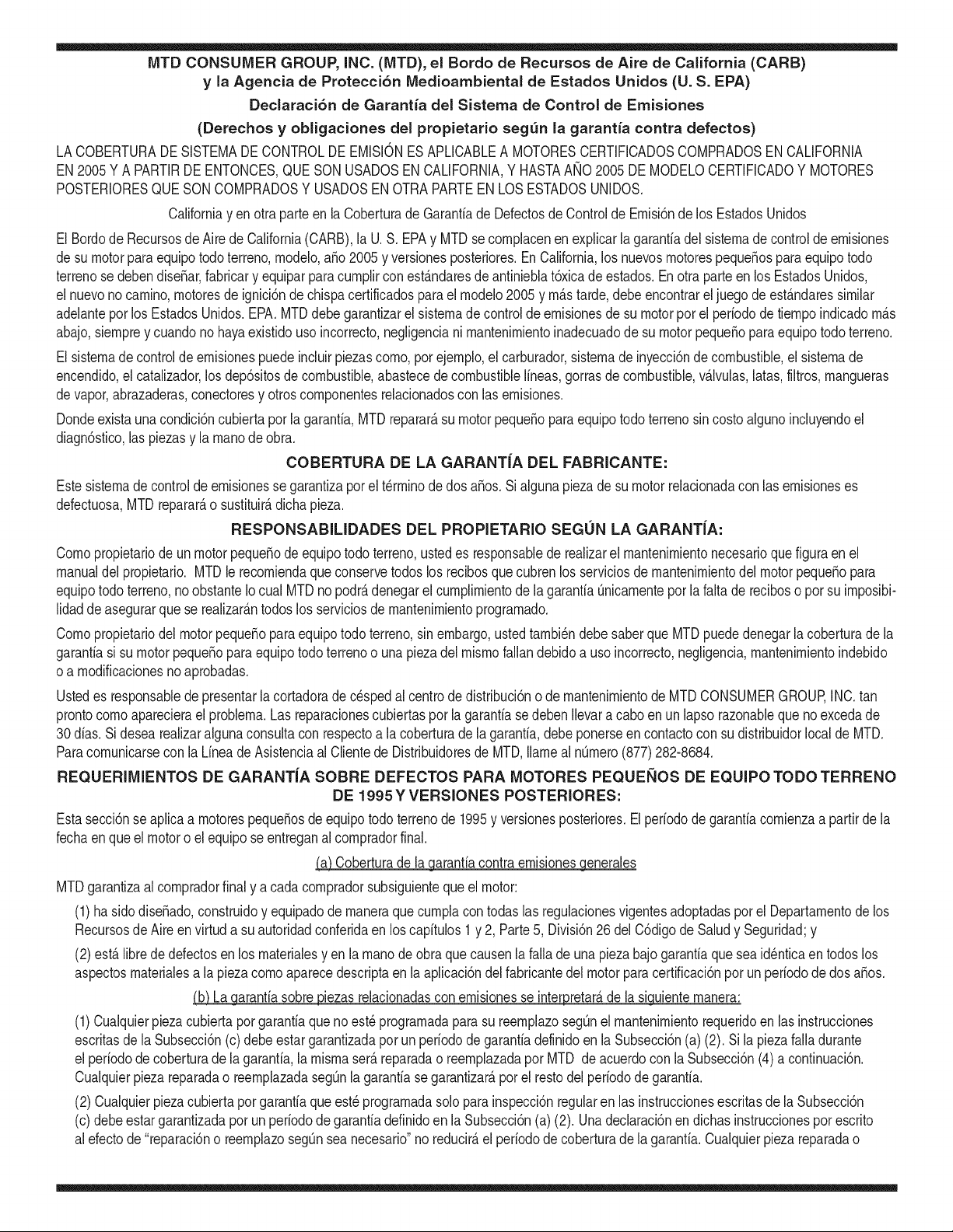
MTD CONSUMER GROUP, iNC. (MTD), el Bordo de Recursos de Aire de California (CARB)
y la Agencia de Protecci6n Medioambiental de Estados Unidos (U. S. EPA)
Declaraci6n de Garantia del Sistema de Control de Emisiones
(Derechos y obligaciones del propietario seg_n la garantia contra defectos)
LACOBERTURADESISTEMADECONTROLDEEMISIONESAPLICABLEA MOTORESCERTIFICADOSCOMPRADOSENCALIFORNIA
EN2005 Y A PARTIRDE ENTONCES,QUESON USADOSEN CALIFORNIA,Y HASTAANO2005DE MODELOCERTIFICADOY MOTORES
POSTERIORESQUESON COMPRADOSY USADOSENOTRAPARTEEN LOSESTADOSUNIDOS.
Californiayen otraparteen la Coberturade Garantiade DefectosdeControlde Emisi6nde los EstadosUnidos
El Bordode Recursosde Airede California(CARB),la U.S. EPAy MTDsecomplacenenexplicarla garantiadel sistemade controldeemisiones
de su motorparaequipotodo terreno,modelo,aSo2005y versionesposteriores.EnCalifornia,los nuevosmotorespequeSosparaequipotodo
terrenose debendise5ar,fabricary equiparparacumplirconest_.ndaresde antinieblat6xicade estados.Enotraparteen los EstadosUnidos,
el nuevonocamino,motoresdeignici6ndechispacertificadospara el modelo2005 y m_.starde,debe encontrarel juego de est_.ndaressimilar
adelantepor los EstadosUnidos.EPA.MTDdebe garantizarel sistemadecontrolde emisionesdesu motorpor elperiodode tiempoindicadom&s
abajo,siemprey cuandono hayaexistidousoincorrecto,negligenciani mantenimientoinadecuadode su motorpequeBoparaequipotodoterreno.
El sistemadecontrolde emisionespuedeincluirpiezascomo,porejemplo,el carburador,sistemade inyecci6ndecombustible,el sistemade
encendido,el catalizador,losdep6sitosde combustible,abastecede combustiblelineas,gorrasde combustible,v&lvulas,latas,filtros,mangueras
devapor,abrazaderas,conectoresy otroscomponentesrelacionadosconlas emisiones.
Dondeexistauna condici6ncubiertaporla garantia,MTDreparar&su motorpequeBoparaequipotodoterrenosincostoalguno incluyendoel
diagn6stico,laspiezasy la manode obra.
COBERTURA DE LA GARANTJA DEL FABRICANTE:
Estesistemade controldeemisionesse garantizapor el t@rminode dos a5os.Si algunapiezade su motorrelacionadacon lasemisioneses
defectuosa,MTD reparar&o sustituir&dichapieza.
RESPONSABJLIDADES DEL PROPIETARIO SEGUN LA GARANTJA:
Comopropietariode un motorpequeSode equipotodoterreno,ustedes responsablede realizarel mantenimientonecesarioquefigura enel
manualdel propietario.MTDle recomiendaque conservetodoslos recibosquecubrenlos serviciosde mantenimientodel motorpeque5opara
equipotodoterreno,no obstanteIo cual MTDno podr&denegarel cumplimientodela garantiaQnicamenteporlafaltade reciboso por su imposibi-
lidadde asegurarquese realizar_.ntodos los serviciosdemantenimientoprogramado.
Comopropietariodel motorpeque5oparaequipotodo terreno,sinembargo,ustedtambi@ndebesaberque MTDpuededenegarlacoberturadela
garantiasi su motorpeque5opara equipotodoterrenoo unapiezadel mismofallandebido a usoincorrecto,negligencia,mantenimientoindebido
oa modificacionesno aprobadas.
Ustedes responsablede presentarla cortadorade cespedal centrode distribuci6no de mantenimientode MTDCONSUMERGROUP,INC.tan
prontocomo aparecierael problem& Lasreparacionescubiertaspor lagarantfasedebenIlevaracabo en un lapsorazonableque noexcedade
30dias.Si desearealizaralgunaconsultacon respectoa la coberturade lagarantia,debeponerseen contactocon su distribuidorlocalde MTD.
Paracomunicarseconla LineadeAsistenciaal Clientede Distribuidoresde MTD,Ilameal nQmero(877)282-8684.
REQUERJMJENTOS DE GARANTJA SOBRE DEFECTOS PARA MOTORES PEQUENOS DE EQUJPO TODO TERRENO
DE 1995YVERSJONES POSTERJORES:
Estasecci6nse aplicaa motorespeque5osdeequipotodo terrenode 1995y versionesposteriores.Elperiododegarantiacomienzaa partirde la
fechaen queel motoro elequiposeentreganal compradorfinal.
(a)Coberturade la garantiacontraemisionesgenerales
MTDgarantizaal compradorfinaly acada compradorsubsiguientequeel motor:
(1)hasido diseSado,construidoy equipadode maneraque cumplacontodaslas regulacionesvigentesadoptadasporel Departamentode los
RecursosdeAire envirtuda suautoridadconferidaen los capitulos1 y 2, Parte5, Divisi6n26del C6digode Saludy Seguridad;y
(2)est,. librede defectosen los materialesyen la manode obraquecausenlafalla deunapiezabajogarantiaque seaid@nticaentodoslos
aspectosmaterialesa lapiezacomoaparecedescriptaen laaplicaci6ndelfabricantedel motorparacertificaci6npor un periodode dos a5os.
Lb/Lagarantiasobre piezasrelacJonadasconemisJonesse interpretar_,de la sJguientemanera:
(1)Cualquierpiezacubierta por garantiaquenoest@programadaparasu reemplazosegQnel mantenimientorequeridoen las instrucciones
escritasdela Subsecci6n(c) debe estar garantizadapor unperiodode garantiadefinidoen la Subsecci6n(a)(2). Sila piezafalladurante
el periododecoberturadela garantia,la mismaser_.reparadao reemplazadaporMTD de acuerdocon la Subsecci6n(4)a continuaci6n.
Cualquierpiezareparadao reemplazadasegQnlagarantiasegarantizarB,porel restodelperiodode garantia.
(2) Cualquierpiezacubiertaporgarantiaque est@programadasoloparainspecci6nregularen las instruccionesescritasde la Subsecci6n
(c) debe estargarantizadapor un periododegarantiadefinidoenla Subsecci6n(a) (2). Unadeclaraci6nen dichasinstruccionespor escrito
alefectode "reparaci6no reemplazosegQnseanecesario"no reducir_,elperiodode coberturade la garantia.Cualquierpiezareparadao
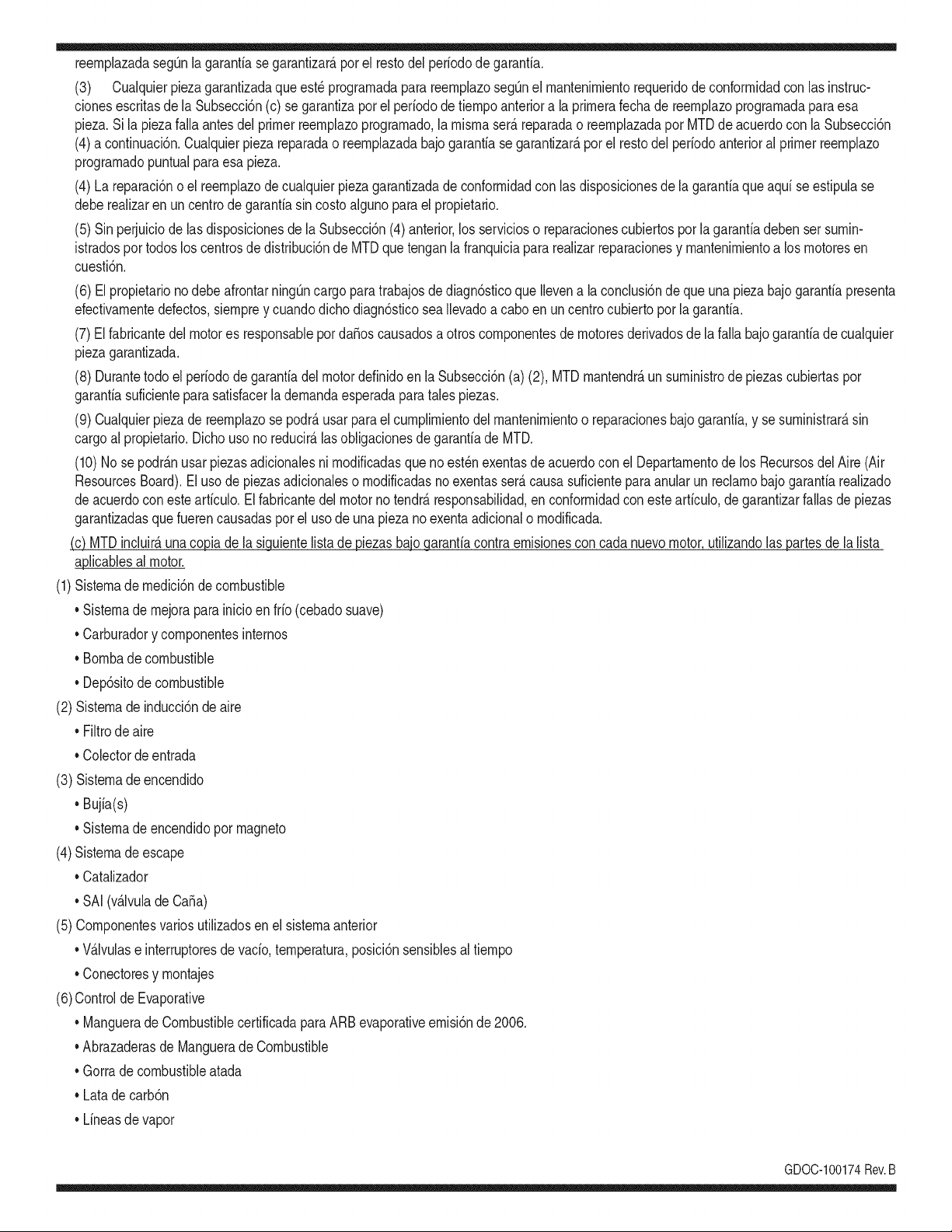
reernplazadasegQnlagarantiasegarantizar_,porelrestodelperiododegarantia.
(3) Cualquierpiezagarantizadaqueest_prograrnadaparareernplazosegQnelrnantenirnientorequeridodeconforrnidadconlasinstruc-
clonesescritasdelaSubsecci6n(c)segarantizaporelperiododetiernpoanterioralaprirnerafechadereernplazoprograrnadaparaesa
pieza.Silapiezafallaantesdelprimerreernplazoprogramatic,larnisrnaser_.reparadaoreernplazadaporMTDdeacuerdoconlaSubsecci6n
(4)acontinuaci6n.Cualquierpiezareparadaoreernplazadabajogaranfiasegarantizar_,porelrestodelperiodoanterioralprimerreernplazo
programaticpuntualparaesapieza.
(4)Lareparaci6noelreernplazodecualquierpiezagarantizadadeconforrnidadconlasdisposicionesdelagaranfiaqueaquiseestipulase
deberealizarenuncentrodegaranfiasincostoalgunoparaelpropietario.
(5)SinperjuiciodelasdisposicionesdelaSubsecci6n(4)anterior,losserviciosoreparacionescubiertosporlagaranfiadebensersurnin-
istradosportodosloscentrosdedistribuci6ndeMTDquetenganlafranquiciapararealizarreparacionesyrnantenirnientoalosrnotoresen
cuesti6n.
(6)ElpropietarionodebeafrontarningQncargoparatrabajosdediagn6sticoqueIlevenalaconclusi6ndequeunapiezabajogaranfiapresenta
efectivarnentedefectos,siernpreycuandodichodiagn6sticoseaIlevadoacaboenuncentrocubiertoporlagarantia.
(7)Elfabricantedelmotoresresponsableporda_oscausadosaotroscornponentesdernotoresderivadosdelafallabajogaranfiadecualquier
piezagarantizada.
(8)DurantetodoelperiododegaranfiadelmotordefinidoenlaSubsecci6n(a)(2),MTDrnantendr_,unsurninistrodepiezascubiertaspor
garantiasuficienteparasatisfacerladernandaesperadaparatalespiezas.
(9)Cualquierpiezadereernplazosepodr_,usarparaelcurnplirnientodelrnantenirnientoo reparacionesbajogaranfia,ysesurninistrar_,sin
cargoalpropietario.Dichousonoreducir_,lasobligacionesdegarantiadeMTD.
(10)Nosepodr_.nusarpiezasadicionalesnirnodificadasquenoest_nexentasdeacuerdoconelDepartarnentodelosRecursosdelAire(Air
ResourcesBoard).Elusodepiezasadicionalesornodificadasnoexentasser_.causasuficienteparaanularunreclarnobajogaranfiarealizado
deacuerdoconestearticulo.Elfabricantedelmotornotendr_,responsabilidad,enconforrnidadconestearticulo,degarantizarfallasdepiezas
garantizadasquefuerencausadasporelusodeunapiezanoexentaadicionalornodificada.
.(c)MTDincluir_,unacopiade lasiguientelistade piezasbajo garantiacontraernisionescon cadanuevomotor,utilizandolas partesde la lista
a_plicablesal motor.
(1)Sisternadernedici6nde combustible
• Sisternade rnejoraparainicioenfrio (cebadosuave)
• Carburadory cornponentesinternos
• Bornbade combustible
• Dep6sitodecombustible
(2) Sisternadeinducci6ndeaire
• Filtrode aire
• Colectordeentrada
(3) Sisternadeencendido
• Bujia(s)
• Sisternade encendidopor magneto
(4)Sisternadeescape
• Catalizador
• SAI (v_Jvulade Ca_a)
(5) Cornponentesvariosutilizadosen el sisternaanterior
• V_Jvulase interruptoresde vado, ternperatura,posici6nsensiblesal tiernpo
• Conectoresy rnontajes
(6)Controlde Evaporative
• Manguerade CombustiblecertificadaparaARB evaporativeernisi6nde 2006.
• Abrazaderasde Manguerade Combustible
• Gorrade combustibleatada
• Latade carb6n
• Lineasde vapor
GD0C-100174Rev.B
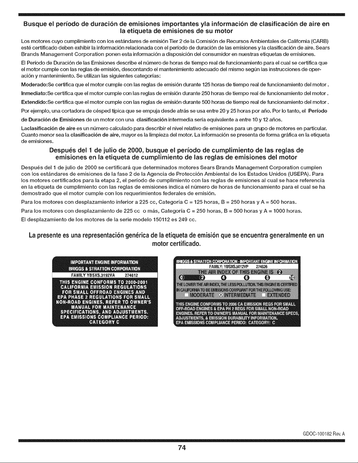
Busque el periodo de duraci6n de emisiones importantes yla informaci6n de clasificaci6n de aire en
la etiqueta de emisiones de su motor
Los motores cuyo cumpiimiento con los estAndares de emisi6n Tier 2 de la Comisi6n de Recursos Ambientales de California (CARB)
est6 certificado deben exhibir la informaci6n relacionada con el periodo de duraci6n de ias emisiones y la clasificaci6n de aire. Sears
Brands Management Corporation ponen esta informaci6n a disposici6n del consumidor en nuestras etiquetas de emisiones.
Ei Periodo de Duraci6n de las Emisiones describe el nQmero de horas de tiempo real de funcionamiento para el cuai se certifica que
el motor cumpie con ias reglas de emisi6n, descontando el mantenimiento adecuado del mismo segQn las instrucciones de oper-
aci6n y mantenimiento. Se utilizan las siguientes categonas:
Moderado:Se certifica que el motor cumpie con las reglas de emisi6n durante 125 horas de tiempo real de funcionamiento del motor.
Inmediato:Se certifica que el motor cumpie con las reglas de emisi6n durante 250 horas de tiempo real de funcionamiento del motor.
Extendido:Se certifica que el motor cumpie con las reglas de emisi6n durante 500 horas de tiempo real de funcionamiento del motor.
Por ejemplo, una cortadora de c6sped tJpica que se empuja desde arras se usa entre 20 y 25 horas por aSo. Por Io tanto, el Periodo
de Duraci6n de Emisiones de un motor con una clasificaci6n intermedia sena equivaiente a entre 10 y 12 aSos.
Laciasificaci6n de aire es un nQmero calculado para describir el nivel relativo de emisiones para un grupo de motores en particular.
Cuanto menor sea la clasificaci6n de aire, mayor es la limpieza del motor. La informaci6n se presenta de forma grAfica en la etiqueta
de emisiones.
Despu_s del 1 de julio de 2000, busque el periodo de cumplimiento de las reglas de
emisiones en la etiqueta de cumplimiento de las reglas de emisiones del motor
Despu6s del 1 de julio de 2000 se certificarA que determinados motores Sears Brands Management Corporation cumplen
con los estAndares de emisiones de la fase 2 de la Agencia de Protecci6n Ambientai de los Estados Unidos (USEPA). Para
los motores certificados para la etapa 2, el periodo de cumplimiento con ias reglas de emisiones al cual se hace referencia
en la etiqueta de cumplimiento con las reglas de emisiones indica el nQmero de horas de funcionamiento para el cual se ha
demostrado que el motor cumple con los requerimientos federales de emisi6n.
Para los motores con desplazamiento inferior a 225 cc, Categoria C = 125 horas, B = 250 horas y A = 500 horas.
Para los motores con desplazamiento de 225 cc o mAs, Categoria C = 250 horas, B = 500 horas y A = 1000 horas.
El desplazamiento de los motores de la serie modelo 150112 es 249 cc.
La presente es una representaci6n gen_rica de la etiqueta de emisi6n que se encuentra generaimente en un
motor certificado.
FAMILYYBSXS.3192VA 274812
GDOC-100182Rev.A
74

Felicitaciones por haber realizado una adquisici6n inteligente. El producto Craftsman® que ha
adquirido esta diseSado y fabricado para brindar muchos aSos de funcionamiento confiable. Pero
como todos los productos a veces puede requerir de reparaciones. Es en ese momento cuando el
disponer de un Acuerdo de protecci6n para reparaciones le puede ahorrar dinero y problemas.
A continuaci6n se detallan los puntos incluidos en el Acuerdo:
[] Servicio experto prestadopor nuestros 10,000 especialistas en reparacionesprofesionales
[] Servicio ilirnitado sin cargo para las piezasy la mano de obra en todas las reparacionescubiertas
[] Reernplazo del producto hasta 1500 d61aressi no es posible reparar el producto cubierto
[] Descuento de 25% del precio normal del servicio y de las piezas relacionadascon el mismo que no esten cubiertas
por el acuerdo; ademas, 25% del precio normal de la verificaci6n de mantenimientopreventivo
[] Ayuda r_pida pot tel_fono - Io IlamamosResoluci6n RApida- el apoyo telef6nico de un Chamusca al representante.
Piense en nosotros como el manual "de un dueSohablador."
Una vez adquirido el Acuerdo, puede programar el servicio con tan s61orealizar una Ilamadatelef6nica. Puede Ilamar en
cualquier momentodel dia o de la noche o programar un servicio en linea.
ElAcuerdo de Protecci6nde Reparaci6nes una compra sin riesgo. Si usted anula por alguna raz6n duranteel periodo de
garantia de producto, proporcionaremos un reembolso Ileno.O, un reembolso prorrateado en cualquier momentodespues
del periodo de garantia de producto expira, iAdquiera hoy su acuerdode protecci6n para reparaciones!
Se aplican determinadas limitaciones y exclusiones. Para obtener informaciTn adicional y precios en los Estados
Unidos Ilame al 1-800-827-6655.
El *Coverage en Canad_ivaria en algunos articulos. Para detalles Ilenos la Ilamada Chamusca Canad_ien 1-800-
361-8885.
Servicio de instalaci6n de Sears
Si desea solicitar la instalaci6n profesionalde Sears de aparatosdomesticos, dispositivos paraabrir portones, calentado-
res de agua y otros articulos domesticosimportantes, en los Estados Unidos o Canada flame al 1-800-4-MY-HOME®.
75

Your Home
For troubleshooting, product manuals and expert advice:
managernylife
www.managemylife.com
For repair - in your home - of all major brand appliances,
lawn and garden equipment, or heating and cooling systems,
no matter who made it, no matter who sold it!
For the replacement parts, accessories and
owner's manuals that you need to do-it-yourself.
For Sears professional installation of home appliances
and items like garage door openers and water heaters.
1-800-4-MY-HOME ® (1-800-469-4663)
Call anytime, day or night (U.S.A. and Canada)
www.sears.com www.sears.ca
Our Home
For repair of carry-in items like vacuums, lawn equipment,
and electronics, call anytime for the location of your nearest
Sears Parts & Repair Service Center
1-800-488-1222 (U.S.A.) 1-800-469-4663 (Canada)
www.sears.com www.sears.ca
To purchase a protection agreement on a product serviced by Sears:
1-800-827-6655 (U.S.A.) 1-800-361-6665 (Canada)
Para pedir servicio de reparaci6n
a domicilio, y para ordenar piezas:
1-888-SU-HOGAR ®
(1-888-784-6427)
www.sears.com
Au Canada pour service en frangais:
1-800-LE-FOYER Mc
(1-800-533-6937)
www.sears.ca
® Registered Trademark / TMTrademark of KCD IP, LLC in the United States, or Sears Brands, LLC in other countries
® Marca Registrada ! TMMarca de Fabrica de KCD IP, LLC en Estados Unidos, o Sears Brands, LLC in otros paises
MCMarque de commerce ! MDMarque deposee de Sears Brands, LLC