Loading ...
Loading ...
Loading ...
9
3.5 INSTALLING NON-INSULATED DUCTS AND DIFFUSERS (CONT’D)
3. INSTALLATION (CONT’D)
Fresh air distribution ductwork (return side connection)
Same as for Central Draw Point, described in step 3.5.2
3.5.3 SIMPLIFIED INSTALLATION (AS ILLUSTRATED IN SECTION 2.3)
Stale air exhaust ductwork (return side connection)
When performing duct connections, always use approved tools and materials. Respect all corresponding
laws and safety regulations. Please refer to your local building code.
WARNING
If using Method 2, make sure the furnace blower operation is synchronized with the HRV/ERV operation!
See Section 5.
CAUTION
!
VJ0109
3’MINIMUM
UNIT DOOR
A + B + C = NOT LESS
THAN 9’ 10”
When performing connection to the furnace supply duct, this duct must be sized to support the additional
air flow produced by the HRV/ERV. Also, use a metal duct with a backdraft damper to prevent the risk of
overheating the HRV/ERV.
CAUTION
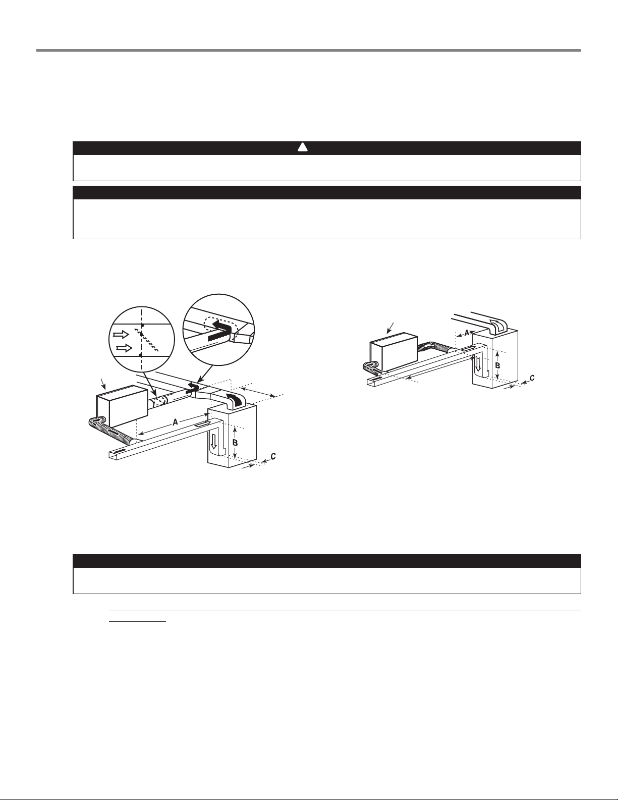
There are 2 methods for connecting the unit to the furnace:
Method 1: Return-supply connection Method 2: Return-return connection
VJ0110
MINIMUM 18”
UNIT DOOR
METAL DUCT WITH
BACKDRAFT DAMPER
A + B + C = NOT LESS
THAN 9’ 10”
Stale air intake:
• Cut an opening into the furnace return duct not less than 9’ 10” from forced air unit drop: (A+B+C).
• Connect this opening to the stale air intake port on the HRV/ERV as shown.
Fresh air distribution: (Same instruction as for Method 1 or Method 2, section 3.5.2)
For Method 2 (return-return), make sure there is a distance of at least 3 feet between both connections to the furnace.
NOTE: For Method 1, it is not essential to synchronize the furnace blower operation with the HRV/ERV operation, but we
recommend it.
Loading ...
Loading ...
Loading ...