Loading ...
Loading ...
Loading ...
19
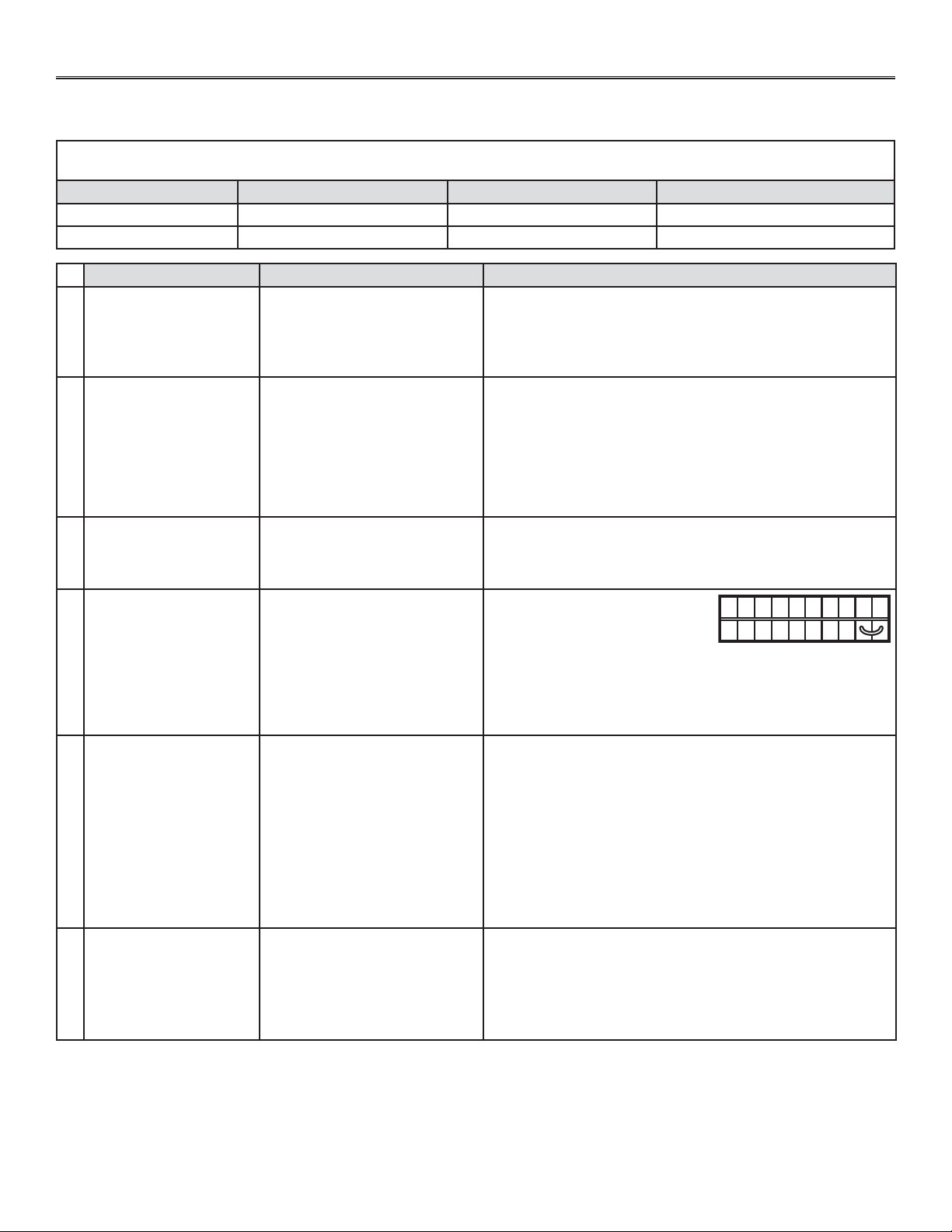
9. TROUBLESHOOTING
If the unit does not work properly, reset the unit by unplugging it for one minute and then replug it. If it is still not working
properly, refer to table below.
If the integrated control LED of the unit is flashing, this means the unit sensors detected a problem. See the table below to know where
the problem occurs on the unit.
LED COLOR ERROR TYPE ACTION UNIT STATUS
LED flashes GREEN Thermistor error Replace thermistor Unit works but will defrost frequently
LED flashes AMBER Damper error Go to point 5 Unit does not work
• Unplug the unit. Disconnect the
main control and the optional
auxiliary control(s) (if need be).
Jump G and B terminals. Plug the
unit back and wait about 10 seconds. If the motors run on high
speed and the damper opens, the circuit board is not defective.
• Check if fuse F1 is blown. In that case, replace fuse F1 as per
product nameplate.
NO C NC I OC OL Y R G B
VE0097
PROBLEMS POSSIBLE CAUSES YOU SOULD TRY THIS
1
The error code E1 is
displayed on VT8W or
VT7W wall control screen.
• The wires may be in reverse
position.
• The wires may be broken.
• The wires may have a bad
connection.
• Ensure that the color coded wires have been connected to their
appropriate places.
• Inspect every wire and replace any that is damaged.
• Ensure the wires are correctly connected.
2
There is no outdoor
temperature displayed on
VT8W wall control screen
__.
• The unit thermistor is defective
(the integrated control LED of
the unit must flash GREEN).
NOTE: At its very start-up or after a power failure, it takes some
minutes before the outdoor temperature appears on
screen. The delay duration depends on which operation
mode the wall control is set. The shortest delay is obtained
when the wall control is set on MIN or MAX in VENT Mode.
• Replace the unit thermistor.
3
VT8W or VT7W wall
control screen alternates
between normal display
and E3.
• The VT8W or VT7W wall control
may be defective.
• Replace the VT8W or VT7W wall control.
4
Unit does not work. • The circuit board
may be defective.
• The fuse may be defective.
5
The damper actuator
does not work.
• The damper actuator or the
integrated damper mechanism
may be defective.
• The circuit board or the
transformer may be defective.
• Unplug the unit. Disconnect the main control and the optional
controls(s) (if need be). Wait 10 seconds and plug the unit back.
Check if the damper opens. If not, use a multimeter and check
for 24 VAC on J12-1 and J12-2 (in electrical compartment). If
there is 24 VAC, replace the entire damper assembly.
NOTE: It is normal to experience a small delay (7-8 seconds)
before detecting the 24 VAC signal at starting-up. This
signal will stay during 17-18 seconds before disappearing.
• If there is no 24 VAC, check for 24 VAC between J8-1 and J8-2.
If there is 24 VAC, replace the circuit board, and if there is no 24
VAC, change the transformer.
6
The wall control does not
work.
• The wires may be in reverse
position.
• The wires may be broken.
• The wire in the wall OR the wall
control may be defective.
• Ensure that the color coded wires have been connected to their
appropriate places.
• Inspect every wire and replace any that are damaged.
• Remove the wall control and test it right beside the unit using
another shorter wire. If the wall control works there, change the
wire. If it does not, change the wall control.
Loading ...
Loading ...
Loading ...