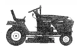

Owner's Manual
cnnFTSn#+
16.5 HP
ELECTRIC START
42" MOWER
6 SPEED TRANSAXLE
LAWN TRACTOR
Model No.
917.271110
• Safety
• Assembly
• Operation
• Maintenance
• Repair Parts
CAUTION:
Read and follow all
Safety Rules and Instructions
before operating this equip-
ment.
For answers to your questions
about this product, Call:
1-800-659-5917
Sears Craftsman Help Line
5am - 5pm, Mon - Sat
Sears, Roebuck and Co., Hoffman Estates, IL 60179
Warranty ................................................. 2
Safety Rules ........................................... 2
Assembly ................................................ 8
Operation.............................................. 12
Maintenance Schedule ......................... 19
Maintenance ......................................... 19
Product Specifications ........................... 5
Service and Adjustments ...................... 23
Storage ................................................. 29
Troubleshooting .................................... 30
Repair Parts ......................................... 34
Parts Ordering ....................... Back Cover
LIMITEDTWOYEAR WARRANTYONCRAFTSMAN RIDING EQUIPMENT
Fortwo(2) yearsfromthedateofpurchase,ifthisCraftsmanRidingEquipmentismain-
tained,lubricatedandtunedupaccordingtotheinstructionsin theowner'smanual,
Searswillrepairor replace,free ofcharge,anypartsfound tobe defectiveinmatedalor
workmanship.
ThisWarrantydoesnotcover:.
• Expendableitemswhichbecomewomduringnormaluse, suchas blades,spark
plugs,air cleaners,belts,etc.
• Tirereplacementorrepaircausedbypuncturesfrom outsideobjects,suchas nails,
thorns,stumps,orglass.
• Repairsnecessarybecauseofoperatorabuse,negligence,improperstorageor acci-
dentor thefailureto maintaintheequipmentaccordingtotheinstructionscontainedin
theowner'smanual.
• Ridingequipmentusedfor commercialorrentalpurposes.
LIMITED90 DAYWARRANTYON BATTERY
Forninety(90) daysfrom dateofpurchase,ifanybatteryincludedwiththisridingequip-
mentprovesdefectivein materialorworkmanshipand ourtestingdeterminesthe bat-
terywillnotholda charge,Searswillreplacethe batteryat nocharge. In-homewarranty
serviceonyourCraftsmanridingequipmentisavailableat no chargefor 30 daysfrom
thedateofpurchase.Pleasecontactyournearestservicecenter.After30 daysfromthe
dateofpurchase,warrantyserviceisavailablebytakingyourCraftsmanridingequip-
menttoyournearestSearsServiceCenter.(In-homewarrantyservicewillstillbe avail-
able after30 daysfrom thedateofpurchasebuta standardtripchargewillapply).This
warrantyappliesonlywhilethisproductisintheUnitedStates.ThisWarrantygivesyou
specificlegalrights, andyoumayalsohaveotherrightswhichmayvaryfrom stateto
state.
Sears, Roebuckand Co., D/817 WA,HoffmanEstates,IL 60179
GENERAL OPERATION
• Read, understand, and follow all instruc-
tions in the manual and on the machine
before starting.
• Only allow responsible adults, who are
familiar with the instructions, to operate
the machine.
• Clear the area of objects such as recks,
toys, wire, etc., which could be picked
up and thrown by the blade.
• Be sure the area is clear ofother people
befO_ mowing. Stop machine if anyone
enters the area.
• Nevercarrypassengers.
• Do notmowin reverseunlessabsolute-
lynecessary.Alwayslookdownand
behindbeforeand whilebacking.
• Beawareofthe mowerdischargedirec-
tionanddo notpointitat anyone.Do
notoperatethemowerwithouteither
theentiregrasscatcherortheguardin
place.
• Slowdownbeforetuming.
• Never leavea running machineunat-
tended.Alwaystumoffblades,set park-
ingbrake,stopengine,and remove
keysbeforedismounting.
•Tum offbladeswhennotmowing.
• Stopenginebeforeremovinggrass
catcheror uncloggingchute.
• Mowonlyindaylightor goodartificial
light.
• Do notoperatethemachinewhileunder
theinfluenceof alcoholor drugs.
• Watchfortrafficwhenoperatingnear or
crossingroadways.
• Useextracarewhenloadingorunload-
ingthe machineintoa trailerortruck.
SLOPE OPERATION
Slopesare a majorfactor relatedtoloss-
of-controland tipoveraccidents,which
canresultinsevereinjuryor death.All
slopesrequireextracaution.Ifyoucannot
backuptheslopeor ifyoufeeluneasyon
it, donot mowit.
DO:
• Mow upand downslopes,notacross.
• Removeobstaclessuchas rocks,tree
limbs,etc.
• Watchforholes,ruts,orbumps.Uneven
terraincouldovertumthemachine.Tall
grasscanhideobstacles.
• Useslowspeed.Choosea lowgearso
thatyouwillnothavetostopor shift
whileon theslope.
• Followthemanufacturer'srecommen-
dationsfor wheelweightsorcounter-
weightstoimprovestability.
• Useextracare withgrasscatchersor
otherattachments.These canchange
the stabilityofthemachine.
• Keepall movementon theslopesslow
andgradual.Donot makesudden
changesinspeedordirection.
• Avoidstartingorstoppingona slope.If
tireslosetraction,disengagetheblades
andproceedslowlystraightdownthe
slope.
DO NOT:
• Do notturnonslopesunlessnecessary,
andthen,turnslowlyandgradually
downhill,ifpossible.
• Do notmowneardrop-offs,ditches,or
embankments.The mowercouldsud-
denlytumoverifa wheel isoverthe
edge ofa clifforditch,or ifanedge
cavesin.
• Doz_ow,Qn wet grass.Reduced
tractioncouldcausesliding.
• Do nottrytostabilizethemachineby
puttingyourfootontheground.
• Donotusegrasscatcheron steep
slopes.
CHILDREN
Tragicaccidentscan occuriftheoperator
is notalerttothepresenceofchildren.
Childrenare oftenattractedtothe
machineandthemowingactivity.Never
assumethatchildrenwillremainwhere
you lastsawthem.
• Keepchildrenout ofthe mowingarea
andunderthewatchfulcare ofanother
responsibleadult.
• Bealsrtandrummachineoffifchildren
enterthe area.
• Beforeand whenbacking,lookbehind
anddownforsmallchildren.
• Nevercarrychildren.They mayfall off
andbe seriouslyinjuredorinterferewith
safe machineoperation.
• Neverallowchildrentooperatethe
machine.
• Useextracarewhenapproachingblind
corners,shrubs,trees,or otherobjects
thatmayobscurevision.
SERVICE
• Useextracareinhandlinggasolineand
otherfuels.They areflammable and
vaporsare explosive.
Use onlyanapprovedcontainer.
- Never removegascapor addfuel
withtheenginerunning.Allowen-
ginetocoolbeforerefueling.Donot
smoke.
- Never refuelthemachineindoors.
- Neverstorethe machineorfuel
containerInsidewhere thereisan
openflame, suchas a waterheater.
• Neverrun a machineinsidea closed
area.
• Keepnutsandbolts,especiallyblade
attachmentbolts,tightand keepequip-
mentingoodcondition.
• Nevertamperwithsafetydevices.
Checktheirproperoperation regularly.
• Keepmachinefree ofgrass,leaves,or
otherdebrisbuild-up.Clean oilorfuel
spillage.Allowmachinetocoolbefore
stodng.
• Stopand inspecttheequipmentifyou
strikean object.Repair,ifnecessary,
beforerestarting.
• Nevermake adjustmentsorrepairswith
theenginerunning.
• Grasscatchercomponentsare subject
towear, damage,and deterioration,
whichcouldexposemovingpartsor
allowobjectstobethrown.Frequently
checkcomponentsand replacewith
manufacturer'srecommendedparis,
when necessary.
Mowerbladesaresharpandcancut.
Wraptheblade(s)orweargloves,and
useextracautionwhenservicing them.
Checkbrakeoperationfrequently.
Adjustand serviceas required.
• Besurethearea isclearofotherpeople
beforemowing.Stopmachineifanyone
entersthearea.
• Nevercarrypassengers.
• Donot mowin reverseunlessabsolute-
lynecessary.Alwayslookdownand
behindbeforeand whilebacking.
• Nevercarrychildren.They mayfall off
and be seriouslyinjuredor interferewith
safe machineoperation.
• Keepchildrenoutofthemowingarea
and underthewatchfulcareofanother
responsibleadult.
• Bealertandturnmachineoffifchildren
enterthearea.
• Beforeandwhenbacking,lookbehind
and downfor smallchildren.
• Mow upanddownslopes(15" Max), not
across.
• Removeobstaclessuchas rooks,tree
limbs,etc.
• Watchfor holes,ruts,orbumps.Uneven
terraincouldovertumthemachine.Tall
grasscanhideobstacles.
• Useslowspeed.Choosea lowgearso
thatyou willnothavetostopor shift
whileontheslope.
• Avoidstartingor stoppingon a slope.If
tireslosetraction,disengagetheblades
and proceedslowlystraightdownthe
slope.
• Do notturnonslopesunlessnecessary,
andthen,turnslowlyand gradually
downhill,ifpossible.
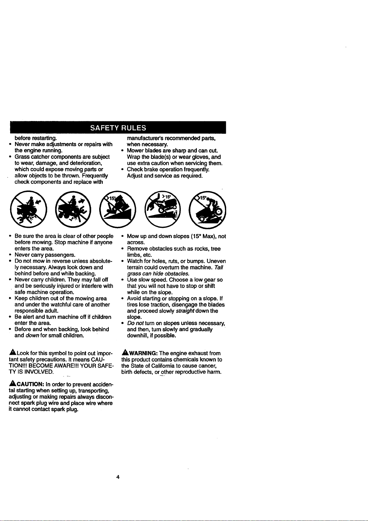
,_Look for thissymbolto pointoutimpor-
tantsafetyprecautions.ItmeansCAU-
TION!!!BECOMEAWARE!!!YOUR SAFE-
TY IS INVOLVED.
_ .,÷
,_CAUTION: In ordertopreventacciden-
talstartingwhensettingup,transporting,
adjustingormakingrepairsalwaysdiscon-
nectsparkplugwireandplacewirewhere
itcannot contactsparkplug.
_WARNING: The engineexhaustfrom
thisproductcontainschemicalsknownto
theStateofCalifomiatocausecancer,
birthdefects,or.otherreproductiveharm.
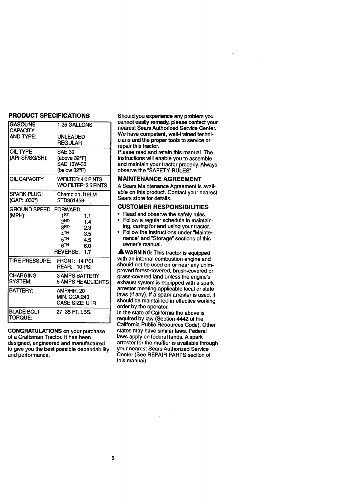
PRODUCT SPECIFICATIONS
GASOLINE 1.25 GALLONS
CAPACITY
AND TYPE: UNLEADED
REGULAR
OIL TYPE SAE 30
(API-SF/SG/SH): (above 32°F)
SAE 10W-30
(below 32°F)
OIL CAPACITY: W/RLTER: 4.0PINTS
WK_FILTER:3.5PINTS
SPARK PLUG: Champion J19LM
GAP: .030") STD361458-
GROUND SPEED FORWARD:
(MPH): 1sr 1.1
2ND 1.4
3RD 2.3
4TM 3.5
5TM 4.5
6TM 6.0
REVERSE: 1.7
TIRE PRESSURE: FRONT: 14 PSI
REAR: 10 PSI
CHARGING 3 AMPS BATTERY
SYSTEM: 5AMPS HEADLIGHTS
BATTERY: AMP/HR: 20
MIN. CCA:240
CASE SIZE: UIR
BLADE BOLT 27-35 FT. LBS.
TORQUE:
CONGRATULATIONSonyourpurchase
ofa Craftsman Tractor. Ithasbeen
designed,engineeredandmanufactured
to giveyouthebestpossibledependability
and performance.
Shouldyouexperienceanyproblemyou
cannoteasilyremedy,pleasecontactyour
nearestSearsAuthorizedServiceCenter.
We havecompetent,well-trainedtechni-
ciansand thepropertoolstoserviceor
repairthistractor.
Pleasereadand retainthismanual.The
instructionswillenableyoutoassemble
and maintainyourtractorproperly.Always
observethe "SAFETY RULES".
MAINTENANCE AGREEMENT
ASearsMaintenanceAgreementisavail-
able onthisproduct.Contactyournearest
Searsstorefor details.
CUSTOMER RESPONSIBILITIES
• Read and observe the safety rules.
• Follow a regular schedule in maintain-
ing, caring for and using your tractor.
• Follow the instructions under =Mainte-
nance" and =Storage" sections ofthis
owner's manual.
,AWARNING: This tractor is equipped
with an internal combustion engine and
should not be used on or near any unim-
proved forest-covered, brush-covered or
grass-covered land unless the engine's
exhaust system is equipped with a spark
arrester meeting applicable local or state
laws (if any). If a spark arrester is used, it
should be maintained in effective working
order by the operator.
In the state of California the above is
required by law (Section 4442 of the
California Public Resources Code). Other
states may have similar laws. Federal
laws apply on federal lands. A spark
arrester for the muffler is available through
your nearest Sears Authorized Service
Center (See REPAIR PARTS section of
this manual).
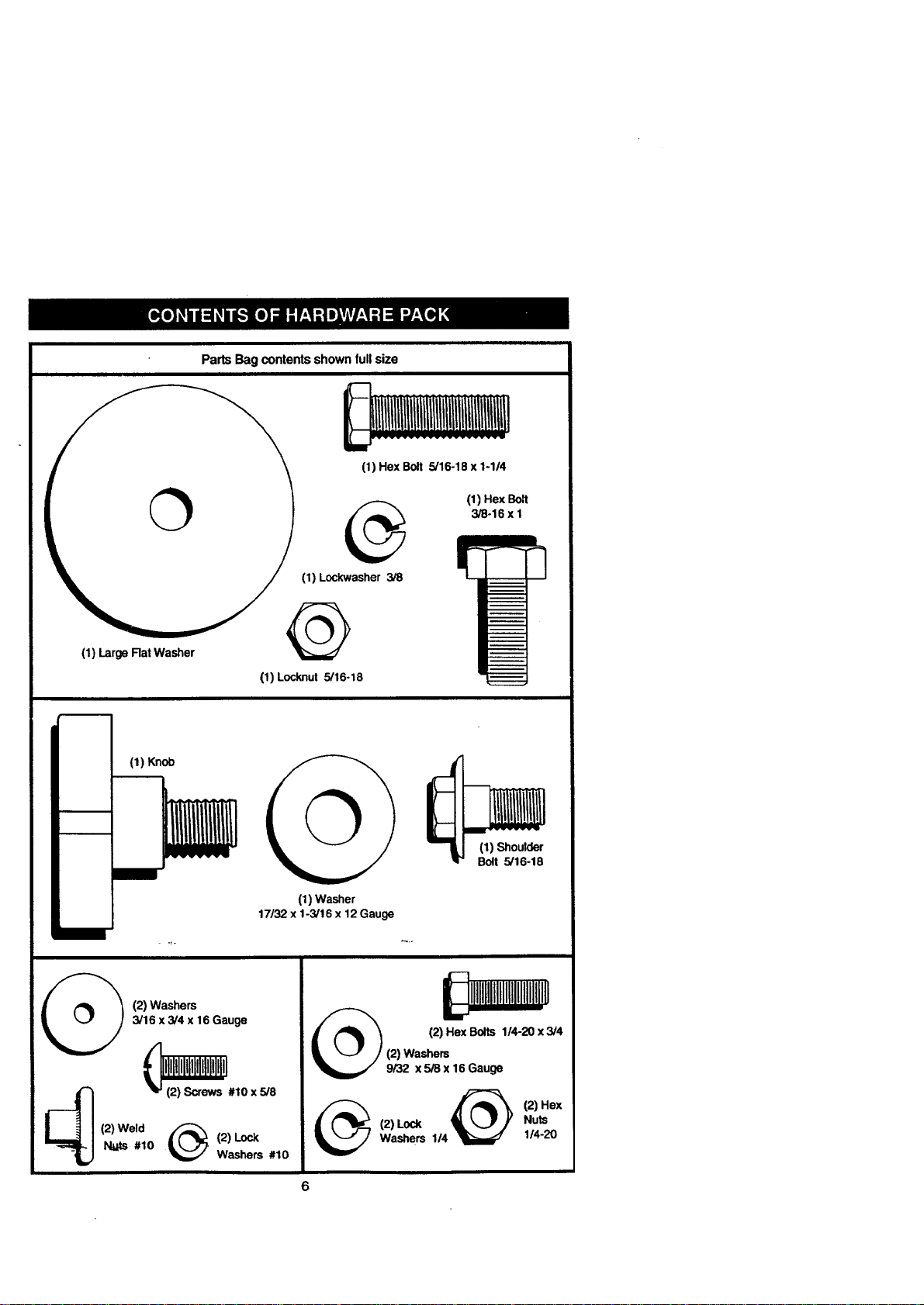
Parts Bag contentsshownfullsize
©
(1) Large Rat Washer
(1) Hex Bolt 5/16-18 x 1-1/4
(1) Hex Bolt
3/8-16 x I
(1) Lockwasher 3/8
Q
(1) Locknut 5/16-18
(1) Knol_
(1) Washer
17/32 x 1-3/16 x 12Gauge
(1) Shoulder
Bolt 5/16-18
_. (2) Weld _.
Nuts #10
(2) Washers
3/16 x3/4 x 16 Gauge
liltlliillllliillllillll
(2) Screws #10 x 5/8
(2) Lock
Washers #10
(2) Hex Bolts 114-20x3/4
@ (2) Hex
(2) Lock Nuts
Washers 1/4 1/4-20
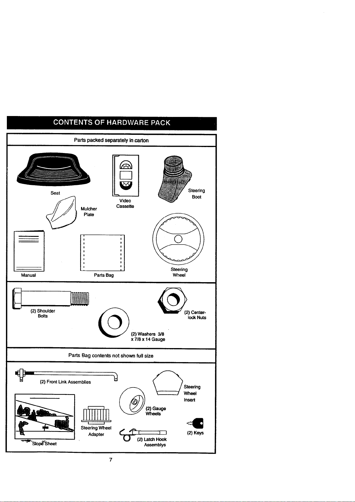
Parts packedseparately in.carton
Manual
(2) Shoulder
Seat
Plate
Video
Cassette
Steering
Boot
I
Parts Bag
Steering
Wheel
Bolts
_(2) Center-
lockNuts
(2) Washers 3/8
x 7/8 x 14 Gauge
Parts Bag contentsnotshownfull size
(2) Front LinkAssemblies
in
Steering Wheel
Adapter
/_ _St_ri_g
Insert
_).._ I 1 (2) Keys
I
(2) Latch Hook
Assemblys
Yournewtractorhasbeenassembledat thefactorywithexceptionofthosepartsleft
unassembledforshippingpurposes.Toensuresafeand properoperationofyourtractor
allpartsandhardwareyouassemblemustbe tightenedsecurely.Usethe correcttools
as necessarytoinsurepropertightness.Reviewthevideocassettebeforeyoubegin.
TOOLS REQUIRED FOR
ASSEMBLY
Asocketwrenchsetwillmakeassembly
easier.Standardwrenchsizesyouneed
arelistedbelow.
(1) 9/16"wrench (1) 3/4"Socketw/
(2) 7/16"wrenches driverachet
(2) 1/2"wrench (1) PhillipsScrew-
(1) 3/4"wrench driver
(1) Utilityknife (1) Tirepressure
(1)Pliers gauge
Whenrightorlefthandismentionedin
thismanual,itmeans,from yourpointo!
view,whenyouare intheoperatingposi-
tion(seatedbehindthesteeringwheel).
TO REMOVE TRACTOR FROM
CARTON
UNPACK CARTON
• Remove all accessible loose parts and
parts boxes from shipping carton (See
page 6).
• Cut, from top to bottom, along lines on
all four comers ofshipping carton, and
lay panels flat.
• Remove mower and package materials.
• Check for any additional loose parts or
boxes and remove.
BEFORE ROLLING TRACTOR OFF
SKID
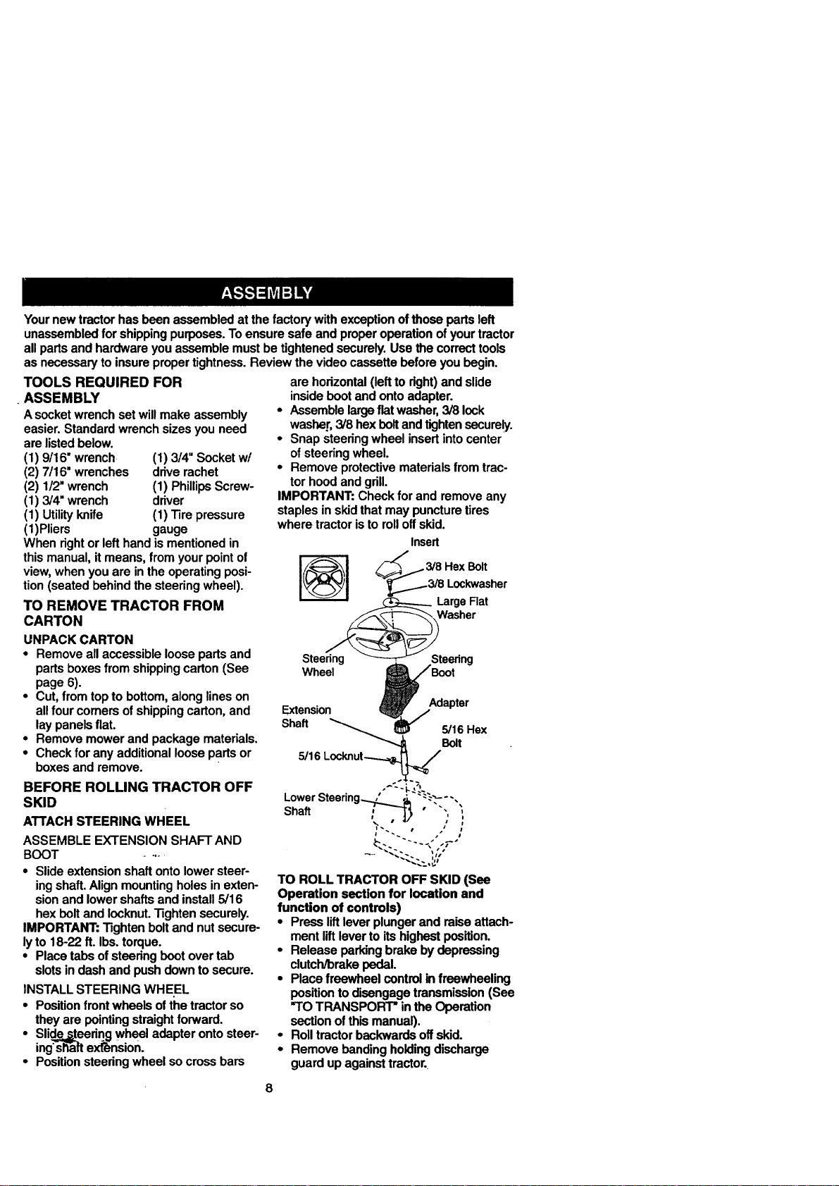
ATTACH STEERING WHEEL
ASSEMBLEEXTENSION SHAFTAND
BOOT - --
• Slideextensionshaftontolowersteer-
ingshaft.Alignmountingholesinexten-
sionand lowershaftsand install5/16
hexboltandIocknut."13ghtensecurely.
IMPORTANT:Tightenboltand nutsecure-
lyto 18-22 ft. Ibs.torque.
• Placetabsofsteeringbootovertab
slotsindashandpushdowntosecure.
INSTALLSTEERING WHEEL
• Positionfrontwheelsofthetractorso
theyare pointingstraightforward.
• Slide_eedng wheeladapterontosteer-
ing'sh_aftextension.
• Positionsteeringwheel socrossbars
are horizontal(leftto dght)and slide
insidebootand ontoadapter.
• Assemblelargeflat washer,3/8 lock
washer,3/8hexboltand tightensecurely.
• Snapsteeringwheelinsertintocenter
ofsteeringwheel.
• Removeprotectivematerialsfromtrac-
tor hoodandgrill.
IMPORTANT:Checkforand removeany
staplesinskidthatmaypuncturetires
wheretractoristo rolloffskid.
Insert
Wheel
Extension Adapter
ha.
5/16Locknut.___
LowerSteering...._ _" :_"---,
Sh . ,"--'-5" "","
\ ,_/ ,, t
"--._ .,-.
".._..:. ,,"
TO ROLLTRACTOR OFF SKID (See
Operation sectionfor location and
function of controls)
• Pressliftleverplungerand raiseattach-
mentliftleverto itshighestposition.
• Releaseparkingbrakebydepressing
clutch/brakepedal.
• Placefreewheelcontrolin freewheeling
position todisengagetransmission(See
"TOTRANSPORT"intheOperation
sectionofthismanual).
• Rolltractorbackwardsoffskid.
• Removebandingholdingdischarge
guardupagainsttractor.
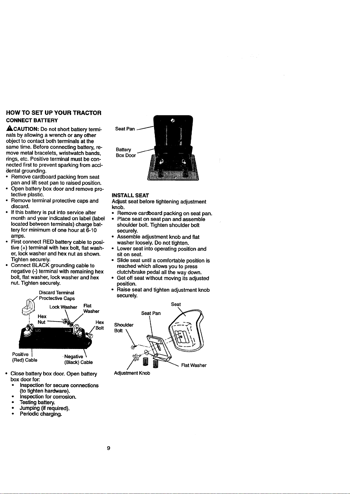
HOW TO SET UP YOUR TRACTOR
CONNECT BATTERY
ACAUTION: Do not short battery termi-
nals by allowing a wrench or any other
object to contact both terminals at the
same time. Before connecting battery, re-
move metal bracelets, wristwatch bands,
rings, etc. Positive terminal must be con-
nected first to prevent sparking from acci-
clental grounding.
• Remove cardboard packing from seat
pan and lift seat pan to raised position.
• Open battery box door and remove pro-
tective plastic.
• Remove terminal protective caps and
discard.
• If this battery is put into service after
month and year indicated on label (label
located between terminals) charge bat-
tery for minimum ofone hour at 6-10
amps.
• First connect RED battery cable to posi-
tive (+) terminal with hex bolt, flat wash-
er, lock washer and hex nut as shown.
Tighten securely.
• Connect BLACK grounding cable to
negative (-) terminal with remaining hex
bolt, flat washer, lock washer and hex
nut. Tighten securely.
Discard Terminal
.i_ Proctec_ve Caps
Lock Washer Flat
Washer
. Hex
Hex
Positive =Negative
(Red) Cable (Black)Cable
• Close batteryboxdoor.Open battery
box doorfor:.
• inspection forsecureconnections
(totightenhardware).
• Inspectionfor corrosion.
• Testingbattery.
• Jumping(ifrequired).
• Periodiccharging.
Seat Pan
Battery
Box Door
INSTALL SEAT
Adjust seat before tightening adjustment
knob.
• Remove cardboard packing on seat pan.
• Place seat on seat pan and assemble
shoulder bolt. Tighten shoulder bolt
securely.
• Assemble adjustment knob and flat
washer loosely. Do nottighten.
• Lower seat intooperating position and
sit on seat.
• Slide seat until a comfortable position is
reached which allows you to press
clutch/brake pedal all the way down.
• Get off seat without moving its adjusted
position.
• Raise seat and tighten adjustment knob
securely.
Seat
Seat Pan
Shoulder
Bolt _._..
Adjustment Knob
Flat Washer
9
CHECKTIREPRESSURE
Thetiresonyourtractorwereovednflated
atthefactoryforshippingpurposes.
Correcttirepressureisimportantforbest
cuttingperformance.
• ReducetirepressuretoPSIshownin
"PRODUCT SPECIFICATIONS" on
page 5 of this manual.
CHECK DECK LEVELNESS
For best cutting results, mower housing
should be properly leveled. See "TO
LEVEL MOWER HOUSING" in the
Service and Adjustments section of this
manual.
CHECK FOR PROPER POSITION OF
ALL BELTS
See thefiguresthatareshownfor replac-
ingmotionandmowerbladedrivebeltsin
theServiceandAdjustmentssectoinof
thismanual.Verifythatthebeltsare mut-
edcorrectly.
CHECK BRAKE SYSTEM
Afteryou learnhowto operateyourtrac-
tor,checktoseethatthebrakeisproperly
adjusted.See "TOADJUST BRAKE"in
theServiceandAdjustmentssectionof
thismanual.
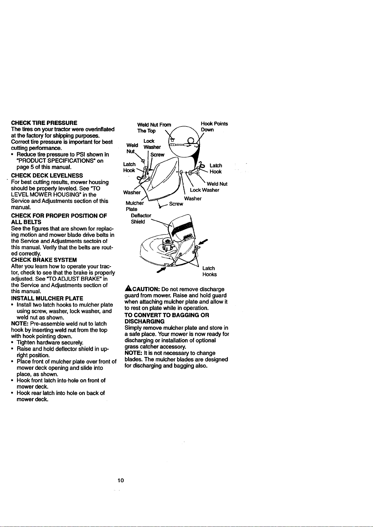
INSTALLMULCHER PLATE
• Installtwolatchhookstomulcherplate
usingscrew,washer,lockwasher,and
weldnutas shown.
NOTE: Pre-assembleweldnutto latch
hookbyinsertingweldnutfromthetop
withhookpointingdown.
• Tightenhardwaresecurely.
• Raiseandholddeflectorshieldin up-
rightposition.
• Placefront ofmulcherplateoverfrontof
mowerdeckopeningandslideinto
place,asshown.
• Hookfront latchinto-holeonfront of
mowerdeck.
• Hookrearlatchintoholeon backof
mowerdeck.
Weld NutFrom
The Top
Lock
Weld Washer
Nut
Latch
HookPoints
Down
Latch
Hook
Washer
Mulcher
Plate
Deflector
Shield
Lock Washer
Washer
Screw
Latch
Hooks
_CAUTION: Donotremovedischarge
guardfrom mower.Raiseand holdguard
whenattachingmulcherplate andallowit
to restonplatewhileinoperation.
TO CONVERT TO BAGGING OR
DISCHARGING
Simplyremovemulcherplate andstorein
a safeplace.Yourmowerisnowreadyfor
dischargingor installationofoptional
grasscatcheraccessory.
NOTE: It isnotnecessarytochange
blades.The mulcherbladesare designed
for dischargingandbaggingalso.
10
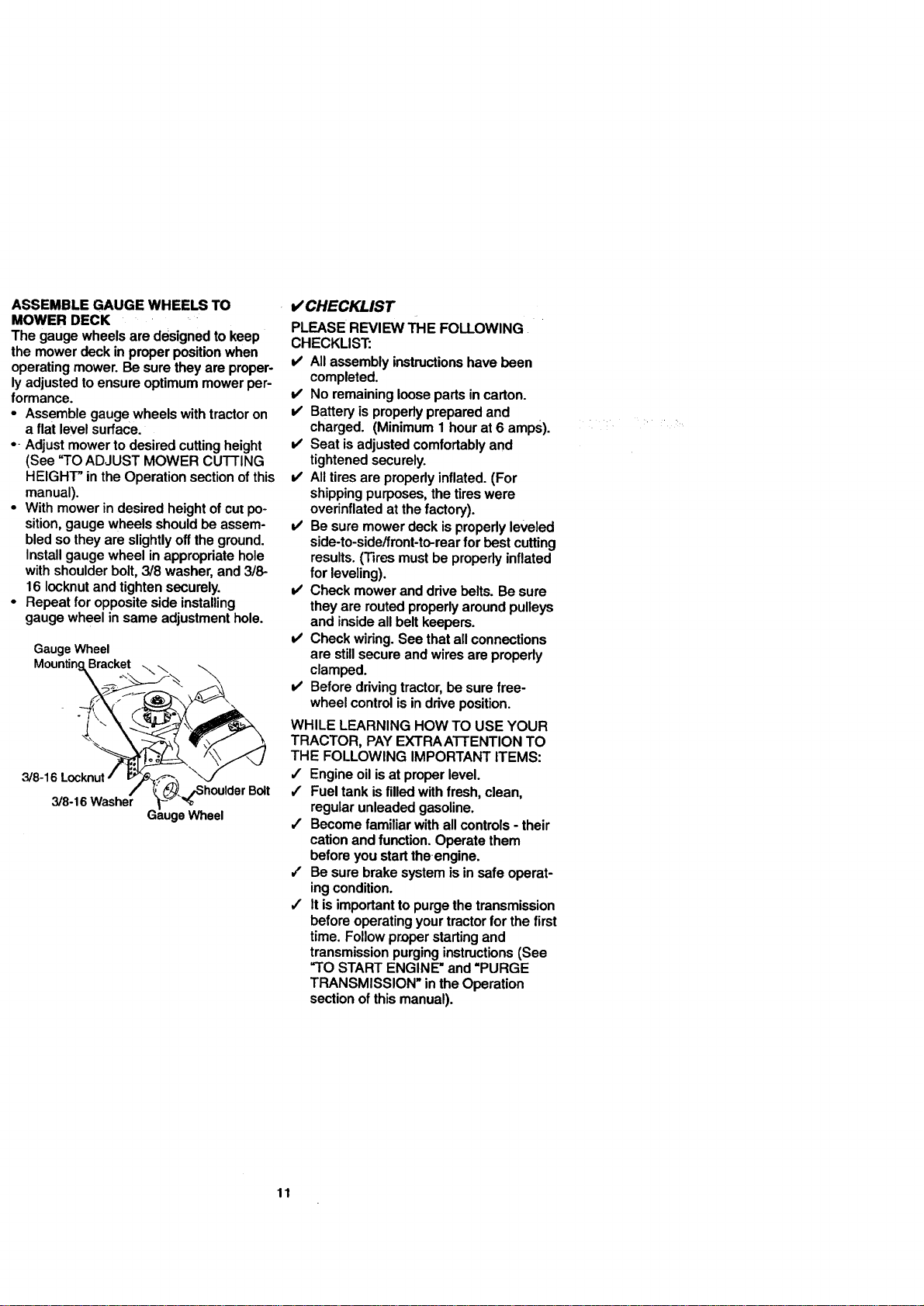
ASSEMBLE GAUGE WHEELS TO
MOWER DECK
The gauge wheels are designed to keep
the mower deck in proper position when
operating mower. Be sure they are proper-
ly adjusted to ensure optimum mower per-
formance.
• Assemble gauge wheels with tractor on
a flat level surface.
• - Adjust mower to desired cutting height
(See "TO ADJUST MOWER CUTTING
HEIGHT" in the Operation section of this
manual).
• With mower in desired height of cut po-
sition, gauge wheels should be assem-
bled so they are slightly off the ground.
Install gauge wheel in appropriate hole
with shoulder bolt, 3/8 washer, and 3/8-
16 Iocknut and tighten securely.
• Repeat for opposite side installing
gauge wheel in same adjustment hole.
Gauge Wheel
Mounting_ racke_ _
3/8-16 Washer Ga_-_ge_Wheel t
V' CHECKLIST
PLEASE REVIEW THE FOLLOWING•
CHECKLIST:
V' All assembly instructionshave been
completed.
v' No remaining loose parts in carton.
v' Battery is properly prepared and
charged. (Minimum 1 hour at 6 amps).
v' Seat isadjusted comfortably and
tightened securely.
v' All tires are properly inflated. (For
shipping purposes, the tires were
overinflated at the factory).
v' Be sure mower deck is propedy leveled
side-to-side/front-to-rear for best cutting
results. (Tires must be properly inflated
for leveling).
v' Check mower and ddve belts. Be sure
they are routed properly around pulleys
and inside all belt keepers.
v' Check widng. See that all connections
are still secure and wires are propedy
clamped.
v' Before driving tractor, be sure free-
wheel control is in ddve position.
WHILE LEARNING HOW TO USE YOUR
TRACTOR, PAY EXTRA ATTENTION TO
THE FOLLOWING IMPORTANT ITEMS:
,/ Engine oil is at proper level.
/ Fuel tank is filled with fresh, clean,
regular unleaded gasoline.
/ Become familiar with all controls - their
cation and function. Operate them
before you start the engine.
/ Be sure brake system is in safe operat-
ing condition.
/ It is important to purge the transmission
before operating your tractor for the first
time. Follow proper starting and
transmission purging instructions (See
"TO START ENGINE" and "PURGE
TRANSMISSION" in the Operation
section of this manual).
11
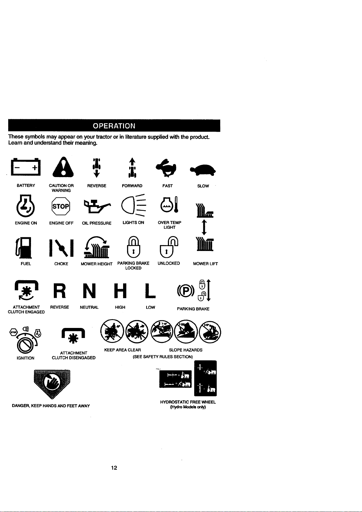
These symbolsmayappearon yourtractororin literaturesuppliedwiththeproduct.
Learnandunderstandtheirmeaning.
BATTERY CAUTION OR REVERSE FORWARD FAST SLOW
WARNING
ENGINE ON ENGINE OFF OIL PRESSURE UGHTS ON OVER TEMP
LIGHT
FUEL CHOKE MOWER HEIGHT PARKING BRAKE UNLOCKED
LOCKED
!
MOWER LIFT
_'l R N H L (®)_1
ATrACHMENT REVERSE NEUTRAL HIGH LOW PARKING BRAKE
CLUTCH ENGAGED
_(_) ATTACHMENT KEEP AREA CLEAR SLOPE HAZARDS
IGNITION CLUTCH DISENGAGED (SEE SAFETY RULES SECTION)
DANGER, KEEP HANDS AND FEET AWAY
HYDROSTATIC FREE WHEEL
(Hydro Mode_ onDy)
12
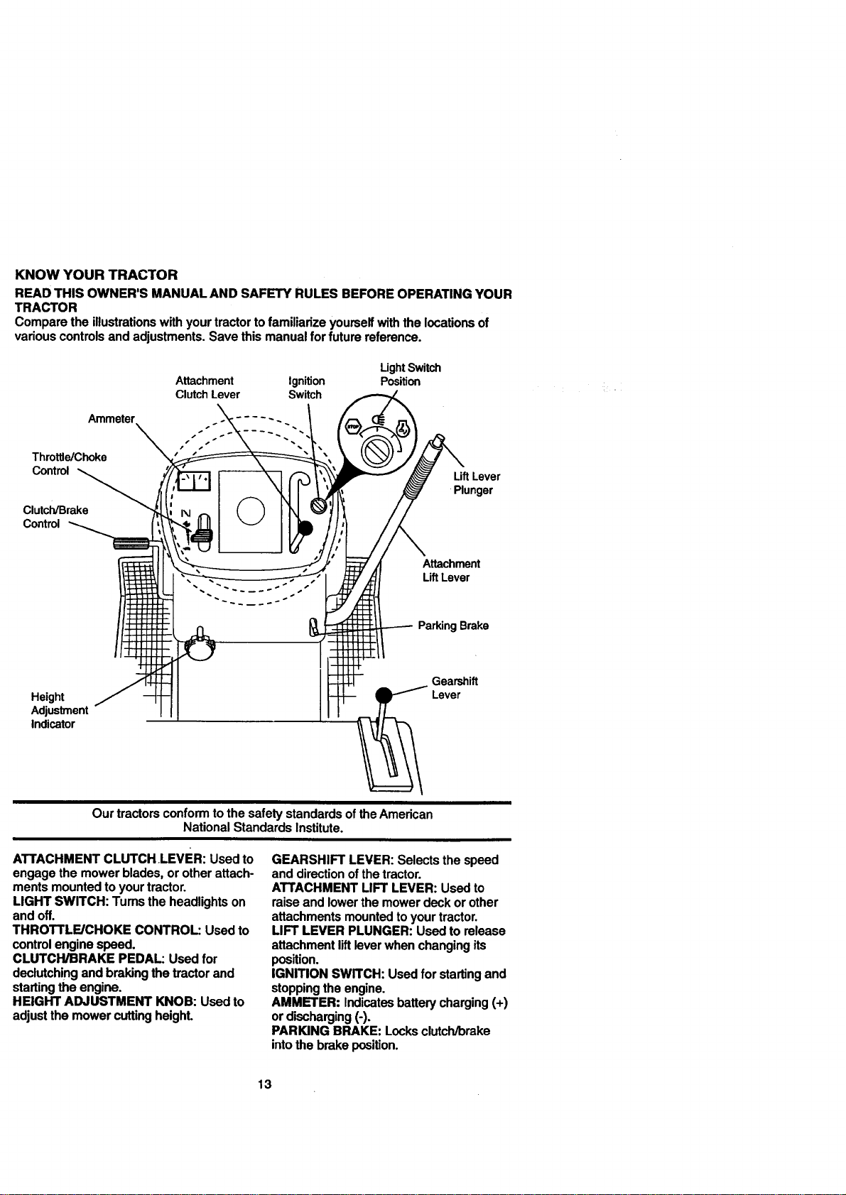
KNOWYOURTRACTOR
READTHISOWNER'SMANUALANDSAFETYRULESBEFOREOPERATINGYOUR
TRACTOR
Comparetheillustrationswithyourtractortofamiliarizeyourselfwiththelocationsof
variouscontrolsandadjustments.Savethismanualforfuturereference.
Attachment Ignition
Clutch Lever Switch
LightSwitch
Position
Throttle/Choke
Control _ LiftLever
Plunger
Clutch/Brake
Control
Height
Adjustment
Indicator
Attachment
Lift Lever
ParkingBrake
Gearshift
Lever
Our tractors conform to the safety standards ofthe American
National Standards Institute.
ATTACHMENTCLUTCH.LEVER:Usedto
engagethe mowerblades,or otherattach-
mentsmountedtoyourtractor.
LIGHT SWITCH:Tums theheadlightson
andoff.
THROTTLE/CHOKE CONTROL: Usedto
controlenginespeed.
CLUTCH/BRAKE PEDAL: Usedfor
declutchingandbrakingthetractorand
startingthe engine.
HEIGHT ADJUSTMENT KNOB: Usedto
adjustthemowercuttingheight.
GEARSHIFT LEVER:Selectsthespeed
anddirectionofthetractor.
ATTACHMENTLIFT LEVER: Usedto
raiseandlowerthe mowerdeckor other
attachmentsmountedtoyourtractor.
LIFT LEVER PLUNGER:Usedtorelease
attachmentliftleverwhenchangingits
position.
IGNITION SWITCH:Usedfor starting and
stoppingtheengine.
AMMETER: Indicatesbatterycharging(+)
ordischarging(-).
PARKINGBRAKE: Locksclutch/brake
intothe brakeposition.
13
The operationofanytractorcanresultinforeignobjectsthrownintothe I
eyes,whichcanresultin severeeye damage.Alwayswearsafetyglasses
I
oreye shieldswhileoperatingyourtractoror performinganyadjustmentsor
repairs.We recommenda widevisionsafetymaskoverthespectacles,or
standardsafetyglasses.
HOW TO USE YOUR TRACTOR
Yourtractorisequippedwithan operator
presencesensingswitch.Whenengineis
running,anyattemptbytheoperatorto
leavethe seatwithoutfirstsettingthe
parkingbrakewillshutofftheengine.
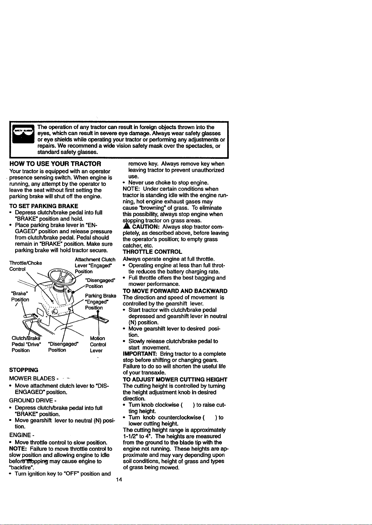
TO SET PARKINGBRAKE
• Depressclutch/brakepedal intofull
=BRAKE"positionand hold.
• Placeparkingbrakeleverin =EN-
GAGED"positionand releasepressure
from clutch/brakepedal.Pedalshould
remainin=BRAKE"position.Makesure
parkingbrakewillholdtractorsecure.
Attachment Clutch
Throttle/Choke Lever=Engaged"
Control Position
\
=Disengaged"
=Brake" ParkingBrake
Position
,,\
Position
Motion
Pedal =Drive" Control
PosilJon Position Lever
STOPPING
MOWER BLADES.....
• Moveattachmentclutchleverto=DIS-
ENGAGED"position.
GROUND DRIVE -
• Depressclutch/brakepedalintofull
=BRAKE"position.
• Movegearshiftleverto neutral(N)posi-
tion.
ENGINE-
• Movethrottle controltoslowposition.
NOTE: Failuretomovethrottle controlto
slowpositionand allowingengineto idle
befotL_oppir_j-maycause engineto
=backfire".
• Turnignition keyto =OFF"positionand
removekey. Alwaysremovekeywhen
leavingtractortopreventunauthorized
USe.
• Neverusechoketostop engine.
NOTE: Undercertainconditionswhen
tractorisstandingidlewiththeenginerun-
ning,hotengineexhaustgasesmay
cause"browning" ofgrass. To eliminate
thispossibility,alwaysstopenginewhen
ppingtractoron grassareas.
CAUTION: Alwaysstoptractorcom-
pletely,as describedabove,beforeleaving
theoperator'sposition;toemptygrass
catcher,etc.
THROTTLE CONTROL
Alwaysoperateengineat full throttle.
• Operatingengineat lessthanfull throt-
tlereducesthe batterychargingrate.
• Fullthrottle offersthebestbaggingand
mowerperformance.
TO MOVE FORWARDAND BACKWARD
The directionandspeedofmovement is
controlledbythe gearshift lever.
• Starttractorwithclutch/brakepedal
depressedandgearshiftleverin neutral
(N) position.
• Move gearshiftlevertodesired posi-
tion.
• Slowlyreleaseclutch/brakepedalto
start movement.
IMPORTANT: Bringtractorto a complete
stopbeforeshiftingorchanginggears.
Failuretodosowillshortentheusefullife
ofyourtransaxle.
TO ADJUST MOWER CUTTING HEIGHT
The cuttingheightiscontrolledbyturning
theheightadjustmentknobindesired
direction.
• Tum knobclockwise( ) toraisecut-
tingheight.
• Turn knob counterclockwise( ) to
lowercuttingheight.
The cuttingheightrangeisapproximately
1-1/2"to4". The heightsare measured
fromthegroundtothe bladetipwiththe
enginenotrunning.These heightsare ap-
proximateand mayvarydependingupon
soilconditions,heightofgrassand types
ofgrassbeing mowed.
14
• The averagelawnshouldbecutto
approximately2-1/2 inchesduringthe
coolseasonandto over3 inchesduring
hotmonths. Forhealthierandbetter
lookinglawns,mowoftenandafter
moderategrowth.
• Forbestcuttingperformance,grass
over6 inchesinheightshouldbe
mowedtwice. Make thefirstcutrela-
tivelyhigh;thesecondtodesiredheight.
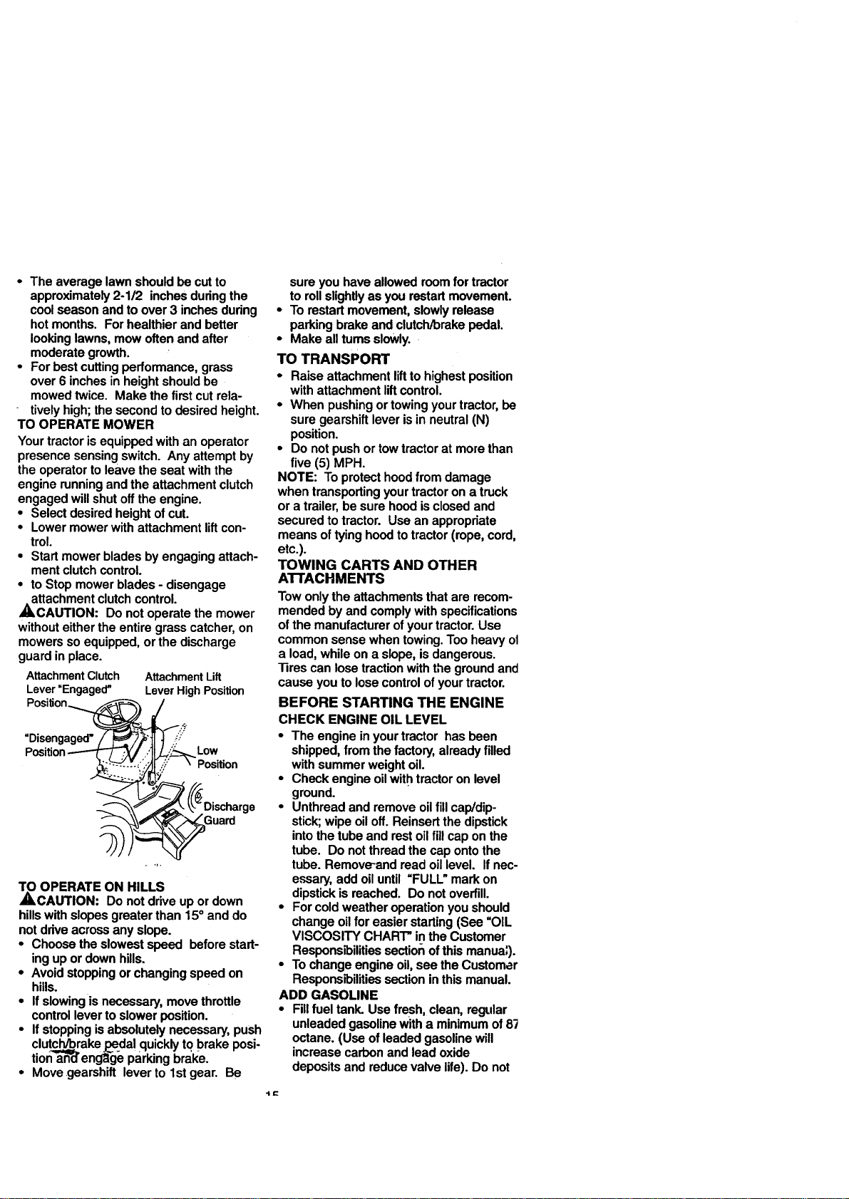
TO OPERATEMOWER
Yourtractorisequippedwithanoperator
presencesensingswitch.Anyattemptby
theoperatortoleavetheseat withthe
enginerunningand the attachmentclutch
engagedwillshutoffthe engine.
• Selectdesiredheightofcut.
• Lowermowerwithattachmentliftcon-
trol.
• Startmowerbladesbyengagingattach-
mentclutchcontrol.
• to Stopmowerblades- disengage
attachmentclutchcontrol.
,_CAUTION: Do notoperatethemower
withouteithertheentiregrasscatcher,on
mowerssoequipped,or thedischarge
guardin place.
Attachment Clutch
Lever "Engaged"
Position
Attachment Lift
Lever High Position
=Disengaged"
Low
Pos_on
Suard
_ OPERATE ON HILLS
CAUTION: Do not drive up or down
hillswith slopes greater than 15° and do
not drive across any slope.
• Choose the slowest speed before start-
ing up or down hills.
• Avoid stopping or changing speed on
hills.
• If slowingis necessary, move throttle
control lever to slower position.
• If stopping is absolutely necessary, push
clutcc,h_=l'Vbrakej3_.dalquickly to brake posio
tiona-a-R_reng_e parking bm'ke.
• Move gearshift lever to 1stgear. Be
sureyouhaveallowedroomfor tractor
torollslightlyas you restartmovement.
• Torestartmovement,slowlyrelease
parkingbrakeandclutch/brakepedal.
• Make alltumsslowly.
TO TRANSPORT
• Raiseattachmentlifttohighestposition
withattachmentliftcontrol.
• Whenpushingor towingyourtractor,be
suregearshiftleverisin neutral(N)
position.
• Do notpushor towtractorat morethan
five (5) MPH.
NOTE: Toprotecthoodfromdamage
whentransportingyourtractoron a truck
or a trailer,besurehoodisclosedand
securedtotractor. Useanappropriate
meansoftyinghoedtotractor(rope,cord,
etc.).
TOWING CARTS AND OTHER
A'I-rACHMENTS
Towonlytheattachmentsthatare recom-
mendedby andcomplywithspecifications
ofthe manufacturerofyourtractor.Use
commonsensewhentowing.Tooheavyot
a load,whileon a slope,isdangerous.
l]res canlosetractionwiththegroundand
causeyouto losecontrolofyourtractor.
BEFORE STARTING THE ENGINE
CHECK ENGINE OIL LEVEL
• The engineinyourtractor hasbeen
shipped,from thefactory,alreadyfilled
withsummerweightoil.
• Checkengineoilwithtractoron level
ground.
• Unthreadand removeoilfillcap/dip-
stick;wipeoiloff.Reinsertthedipstick
intothetubeand restoilfill capon the
tube. Do notthreadthecapontothe
tube. Remove-andreadoillevel. If nec-
essary,add oiluntil =FULL_markon
dipstickisreached. Do notoverfill.
• Forcoldweatheroperationyoushould
changeoilforeasierstarting(See "OIL
VISCOSITY CHART"intheCustomer
Responsibilitiessection ofthismanua;).
• Tochangeengineoil,see the Customar
Responsibilitiessectioninthismanual.
ADD GASOLINE
• Fillfuel tank. Usefresh,clean,regular
unleadedgasolinewitha minimumof8"_
octane.(Useofleadedgasolinewill
increasecarbonandlead oxide
depositsandreducevalvelife).Do not
mixoilwithgasoline.Purchasefuelin
quantitiesthatcanbeusedwithin30
daystoassurefuelfreshness.
IMPORTANT:Whenoperatingintempera-
turesbelow 32°F(0°C), usefresh, clean
wintergradegasolinetohelpinsuregood
,_dAweatherstarting.
RNING: Experienceindicatesthat
alcoholblendedfuels (calledgasoholor
-usingethanolor methanol)canattract
moisturewhichleadstoseparationand
formationofacidsduringstorage.Acidic
gascandamagethefuel systemofan
enginewhileinstorage.Toavoidengine
problems,thefuel systemshouldbe emp-
tied beforestorageof30 daysorlonger.
Drainthegastank, starttheengineand
letitrununtilthefuel linesandcarburetor
areempty.Usefresh fuel nextseason.
See StorageInstructionsfor additional
information.Never useengineorcarbure-
torcleanerproductsinthefuel tankor per-
nentdamagemay occur.
CAUTION: Fillto bottomofgastank
fillerneck.Do notoverfill.Wipeoffany
spilledoilorfuel. Do notstore,spilloruse
gasolinenearan openflame.
TO START ENGINE
Whenstartingthe enginefor thefirst time
or iftheenginehasrunoutoffuel,itwill
take extracrankingtimeto movefuel from
thetanktotheengine.
• Siton seat inoperatingposition,
depressclutch/brakepedaland set
parkingbrake.
• Placegear shiftleverin neutral(N)posi-
tion.
• Moveattachmentclutchto=DISEN-
GAGED"position.
• Movethrottlecontroltochokeposition.
Note: Beforestarting readthewarmand
coldstartingproceduresbelow.
• Insertkey intoignitionandtumkey
clockwiseto=START"positionand
releasekey as soonas enginestarts.
Do notrunstartercontinuouslyfor more
thanfifteen secondsper minute.Ifthe
enginedoesnotstartafterseveral
attempts,movethrottle controltofast
position,waita few minutesandtry
again.If enginestilldoesnotstart,
movethe throttlecontrol beck tothe
chokepositionand retry.
WARM WEATHERSTARTING(50° F
ANDABOVE)
• Whenenginestarts,movethe throttle
controltothefast position.
• The attachmentsand grounddrivecan
nowbe used.If theenginedoesnot
accepttheload, restarttheengineand
allowittowarmupfor one minuteusing
thechokeas describedabove.
COLD WEATHERSTARTING( 50° F
AND BELOW)
• When enginestarts,allowengineto run
withthethrottlecontrolinthechoke
positionuntiltheenginerunsroughly,
then movethrottlecontroltofast posi-
tion.Thismay requireanenginewarm-
upperiodfrom severalsecondstosev-
eralminutes,dependingonthetemper-
ature.
• The attachmentscanalsobeuseddur-
ingtheenginewarm-upperiod.
NOTE: Ifat a highaltitude(above3000
feet) or incoldtemperatures(below32 F)
the carburetorfuel mixturemayneed tobe
adjustedfor bestengineperformance.
See =TOADJUST CARBURETOR"inthe
ServiceandAdjustmentssectionofthis
manual.
MOWING TIPS
• "13rechainscannotbeusedwhenthe
mowerhousingisattachedtotractor.
• Mowershouldbeproperlyleveledfor
bestmowingperformance.See =TO
LEVELMOWER HOUSING"inthe
ServiceandAdjustmentssectionofthis
manual.
• The lefthandsideof mowershouldbe
usedfor trimming.
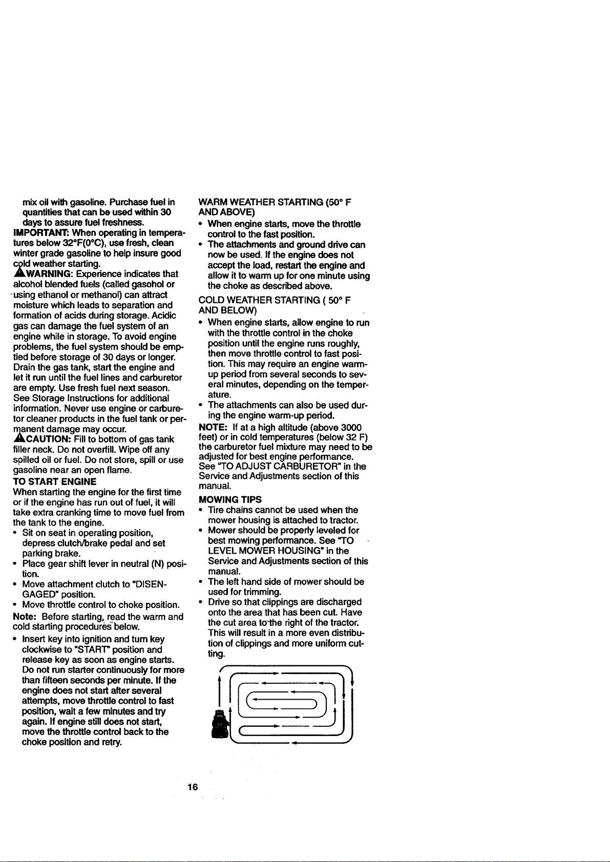
• Drivesothatclippingsaredischarged
ontothe areathathasbeen cut.Have
thecutareato-therightofthetractor.
Thiswillresultina moreevendistribu-
tionofclippingsandmoreuniformcut-
ting.
16
• When mowing large areas, start by turn-
ing to the right so that clippings will dis-
charge away from shrubs, fences, drive-
ways, etc. After one or two rounds, mow
in the opposite direction making left
hand tums until finished.
• Ifgrass is extremely tall, it should be
mowed twice to reduce load and possi-
ble fire hazard trom dried clippings.
Make first cut relatively high;the second
to the desired height.
• Do not mow grass when it is wet. Wet
grass will plug mower and leave unde-
sirable clumps. Allow grass to dry
before mowing.
• Always operate engine at full throttle
when mowing to assure better mowing
performance and proper discharge of
material. Regulate ground speed by se-
lecting a low enough gear to give the
mower the best cutting performance as
well as the quality of cut desired.
• When operating attachments, select a
ground speed that willsuit the terrain
and give best performance of the at-
tachment being used.
MULCHING MOWING TIPS
IMPORTANT: For best performance, keep
mower housing free of built-up grass and
trash. Clean after each use.
• The special mulching blade will recut
the grass clippings many times and
reduce them in size so that as they fall
onto the lawn they will disperse into the
grass and not be noticed. Also, the
mulched grass will biodegrade quickly
to provide nutrients for the lawn. Always
mulchwithyourhighestengine(blade)
speedas thiswill providethebestrecut-
tingactionoftheblades.
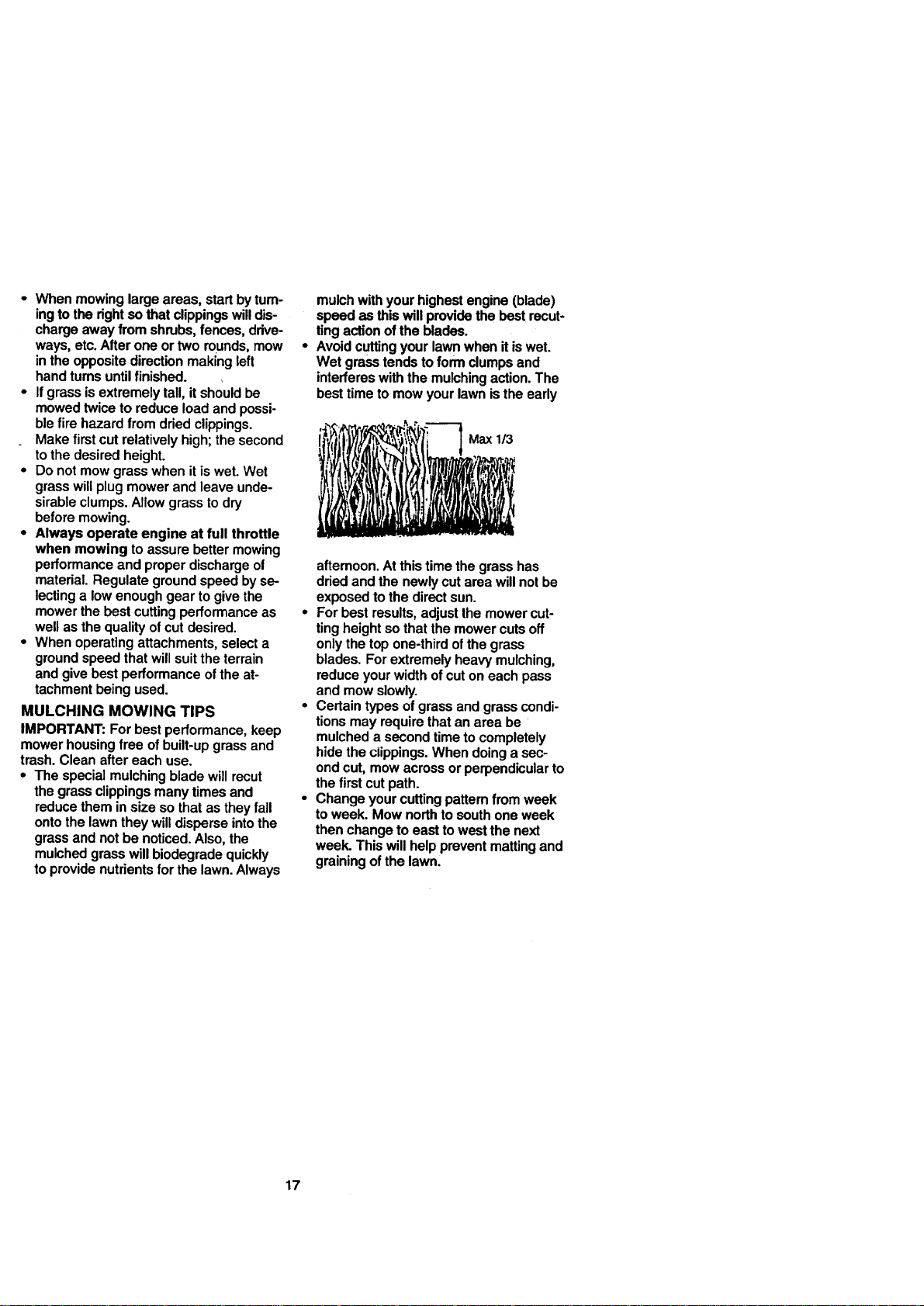
Avoidcuttingyourlawnwhenit iswet.
Wetgrasstendstoform clumpsand
interfereswiththemulchingaction.The
besttimetomowyourlawnisthe early
! ,' I I,
aftemoon.Atthis timethegrasshas
driedandthe newlycutareawillnotbe
exposedtothedirectsun.
• Forbestresults,adjustthemowercut-
tingheightsothatthemowercutsoff
onlythetopone-thirdofthe grass
blades.Forextremelyheavymulching,
reduceyourwidthofcutoneachpass
andmowslowly.
• Certaintypesofgrassand grasscondi-
tionsmayrequirethatanarea be
mulcheda secondtimetocompletely
hidetheclippings.Whendoinga sec-
ondcut,mowacrossorperpendicularto
thefirst cutpath.
• Changeyourcuttingpatternfrom week
toweek. Mownorthtosouthoneweek
thenchangeto easttowestthenext
week.Thiswillhelppreventmattingand
grainingofthelawn.
17
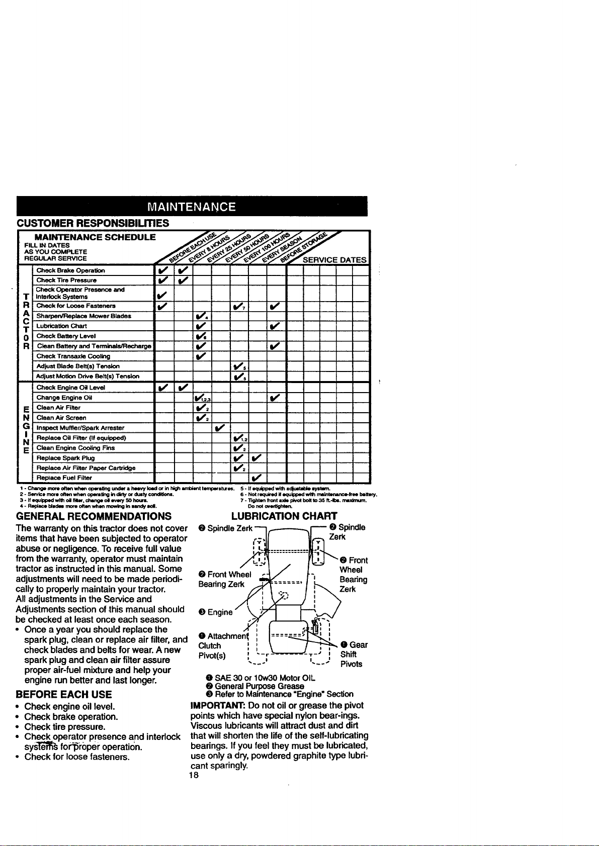
CUSTOMER RESPONSIBILITIES
MAINTENANCE SCHEDULE _./_ __..,,,__.,,_€.J
AS YOU COMPLETE
DATES
lie
Check Brake Operation t_ V p
Check Tire Pressure I_
i Check Operator Presence and
T : Intedock Systems V °
R CheckforLooseFa_enera V* I,/, l/
SharperdIReplace Mower Blades V_4
T LuStre.onChart V' I/
Check Battery Level
Clean Battery and Terminals/Recharge V r V _
Check Transaxla Cooling
Ad}ust Blade Belt(s) Tension Ks
Adjust Motion Drive Ball(s) Tension I_s
Check Engine Oil Level V ° V °
Change Engine Oil IV_1_.3 V*
E Clean Air Filter i V'2
N Clean Air Screen ! V_2
G Inspect Muffler/Spark Arraster I_
Replace Oil Filter (If equipped) V_1.2
N Clean Engine Co_ing Fins VP2
Replace Spark Plug If ll_
Replace Air Filter Paper Cartridge V_2
Replace Fuel Filter V'
1 - Change more often when operstlng undM a heavy load or in high ambient tempeqat_r_. 5 * If equipped with adjustable systern.
2 - Service more o/len when opeflmting ;n dirty cx dusty €ondltlons.
3 - If equipped v*l_ o;I rdtwo Ohange oil evely 50 hourL
4 - Replace blmdN moreoqtenwhon _ insandy soil.
GENERAL RECOMMENDATIONS
The warrantyonthistractordoesnotcover
itemsthathavebeen subjectedtooperator
abuseor negligence.To receivefullvalue
from thewarranty,operatormustmaintain
tractoras instructedin thismanual.Some
adjustmentswillneedtobe madeperiodi-
callyto properlymaintainyourtractor.
All adjustmentsin theServiceand
Adjustmentssectionofthis manualshould
be checkedat leastonceeachseason.
• Oncea yearyoushouldreplacethe
sparkplug,cleanor replaceairfilter,and
checkbladesandbeltsfor wear.A new
sparkplugandcleanair filter assure
properair-fuelmixtureand helpyour
enginerunbetterand lastlonger.
BEFORE EACH USE
• Checkengineoillevel.
• Checkbrakeoperation.
• Checktirepressure.
• Ch_k operatorpresenceand interlock
sys_'d_ fo_lSroperoperation.
• Checkfor loosefasteners.
6 - Not required if equipped with rnalntenance-_ee better,/.
7 - Tighten front rode plvol bon to 35 ft.-Ibs, _.
Do no__.
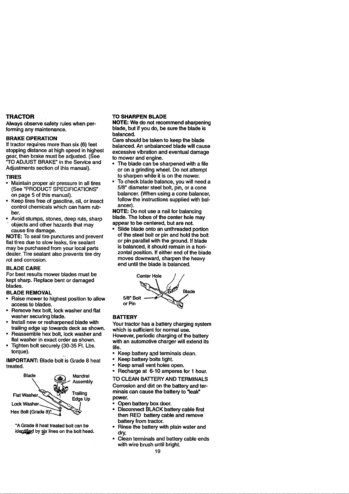
LUBRICATION CHART
O Spindle
Zerk
O FrontWheel Wheel
BearingZerk Bearing
Zerk
0 Enc
0 Attachment_ :
Clutch • Gear
Pivot(s) _ "-_" T-_ _ Shift
...... Pivots
O SAE 30 or 10w30MotorOIL
e GeneralPurposeGrease
@ RefertoMaintenance"Engine"Section
IMPORTANT: Do not oil or grease the pivot
points which have special nylon bear-ings.
Viscous lubricants will attract dust and dirt
that will shorten the life ofthe self-lubricating
bearings. If you feel they must be lubricated,
use only a dry,powdered graphite type lubri-
cant sparingly.
18
TRACTOR
Alwaysobservesafetyruleswhenper-
forminganymaintenance.
BRAKE OPERATION
If tractor requires more than six (6) feet
stopping distance at high speed in highest
gear, then brake must be adjusted. (See
"TO ADJUST BRAKE" in the Service and
Adjustments sectionof this manual).
TIRES
• Maintain proper air pressure in all tires
(See "PRODUCT SPECIFICATIONS"
on page 5 of this manual).
• Keep tires free of gasoline, oil, or insect
control chemicals which can harm rub-
ber.
• Avoid stumps, stones, deep ruts, sharp
" objects and other hazards that may
cause tire damage.
NOTE: To seal tire punctures and prevent
flat tires due to slow leaks, tire sealant
may be purchased from your local parts
dealer. Tire sealant also prevents tire dry
rot and corrosion.
BLADE CARE
For best results mower blades must be
kept sharp. Replace bent or damaged
blades.
BLADE REMOVAL
• Raise mower to highest position to allow
access to blades.
• Remove hex bolt, lock washer and flat
washer securing blade.
• Install new or resharpened blade with
trailing edge up towards deck as shown.
• Reassemble hex bolt, lock washer and
fiat washer in exact order as shown.
• "13ghtenbolt securely (30-35 Ft. Lbs.
torque).
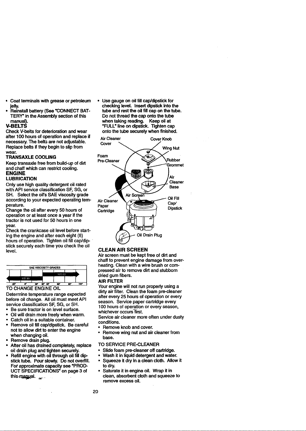
IMPORTANT: Blade b01t'is--Grade 8 heat
treated.
Bladher___ Mandrel
Assembly
FlatWas Trailing
EdgeUp
•oc.
Hex Bolt(Grade8)_.._
*A Grade 8 heat treated bolt can be
ide!;l_, by,_x lines on the bolt head.
TO SHARPEN BLADE
NOTE: We do not recommend sharpening
blade, butif you do, be sure the blade is
balanced.
Care should be taken to keep the blade
balanced. An unbalanced blade will cause
excessive vibration and eventual damage
to mower and engine.
• The blade can be sharpened with a file
or on a grinding wheel. Do not attempt
to sharpen while it ison the mower.
• To check blade balance, you will need a
5/8" diameter steel bolt, pin, or a cone
balancer. (When using a cone balancer,
follow the instructions supplied with bal-
ancer).
NOTE: Do not use a nail for balancing
blade. The lobes ofthe center hole may
appear to be centered, but are not.
• Slide blade onto an unthreaded portion
of the steel bolt or pin and hold the bolt
or pin parallel with the ground. If blade
is balanced, it should remain in a hori-
zontal position. If either end of the blade
moves downward, sharpen the heavy
end until the blade is balanced.
CenterHole
5/8"Bolt
orPin
Blade
BATTERY
Yourtractorhasa batterychargingsystem
whichissufficientfornormaluse.
However,periodicchargingofthebattery
withan automotivechargerwillextendits
life.
• Keepbatteryandterminalsclean.
• Keepbatteryboltstight.
• Keepsmallventholesopen.
• Rechargeat 6-10 amperesfor 1 hour.
TO CLEAN BATTERYANDTERMINALS
Corrosionand dirtonthebatteryandter-
minalscancausethebatteryto"leak"
power.
• Openbatteryboxdoor.
• DisconnectBLACKbatterycablefirst
thenRED batterycableand remove
batteryfrom tractor.
• Rinsethebatterywithplainwaterand
dry.
• Cleanterminalsandbatterycableends
withwirebrushuntilbright.
19
• Coat terminals with grease or petroleum
jelly.
• Reinstall battery (See =CONNECT BAT-
TERY" in the Assembly section of this
manual).
V-BELTS
Check V-belts for deterioration and wear
after 100 hours of operation and replace if
necessary. The belt3 are not adjustable.
Replace belts if they begin to slip from
wear.
TRANSAXLE COOLING
Keep transaxle free from build-up of dirt
and chaff which can restrict cooling.
ENGINE
LUBRICATION
Only use high quality detergent oil rated
with API service classification SF, SG, or
SH. Select the oil's SAE viscosity grade
according to your expected operating tem-
perature.
Change the oil alter every 50 hours of
operation or at least once a year ifthe
tractor is not used for 50 hours in one
year.
Check the crankcase oil level before start-
ing the engine and after each eight (8)
hours of operation. Tighten oil fill cap/dip-
stick securely each time you check the oil
level.
SAE VISCOSITY GRADES
T()_HANGE _N_'E O_
Determinetemperaturerangeexpected
beforeoilchange. AlloilmustmeetAPI
serviceclassificationSF,SG, orSH.
• Besuretractorisonlevelsurface.
• Oilwilldrainmorefreely whenwarm.
• Catchoilin a suitablecontainer.
• Removeoilfillcap/dipstick.Becareful
nottoallowdirttoentertheengine
when changingoil
• Removedrainplug.
• Afteroilhasdrainedcompletely,replace
oildrainplugandtightensecurely.
• Refillenginewitho=3throughoilfill dip-
sticktube. Pourslowly. Donotoverfill.
Forapproximatecapacitysee=PROD-
UCT SPECIFICATIONS"onpage3 of
this.ro,_, al..;... _
• Use gauge on oiltill cap/dipstick for
checking level. Insert dipstick intothe
tube and restthe oUfill cap on the tube.
Do not thread the cap onto the tube
when taking reading. Keep oil at
=FULL=line on dipstick. Tighten cap
onto the tube securely when finished.
AirCleaner CoverKnob
Cover
Foam
Pre-Cleaner
Wing Nut
Air
Cleaner
Base
Oil Fill
Air Cleaner Cap/
Paper Dipstick
Cartridge
OilDrain Plug
CLEAN AIR SCREEN
Air screen must be kept free of dirt and
chaff to prevent engine damage from over-
heating. Clean with a wire brush or com-
pressed air to remove dirt and stubborn
dried gum fibers.
AIR FILTER
Your engine will not run properly using a
dirty air filter. Clean the foam pre-cleaner
after every 25 hours of operation or every
season. Service paper cartridge every
100 hours of operation or every season,
whichever occurs-flrst.
Service air cleaner more often under dusty
conditions.
• Remove knob and cover.
• Remove wing nut and air cleaner from
base.
TO SERVICEPRE-CLEANER
• Slidefoampre_leaner offcartridge.
• Wash it inliquiddetergentand water.
• Squeezeitdryina cleancloth. Allowit
todry.
• Saturateitinengineoil. Wrap itin
clean,absorbentclothand squeezeto
removeexcessoil.
2O
TOSERVICECARTRIDGE
• Replace a dirty, bent, or damaged car-
tridge.
NOTE: Do not wash the paper cartridge
or use pressurized air, as this will damage
the cartddge.
• Reinstall the pre-cleaner (cleaned and
oiled) over the paper cartridge.
• Reassemble air cleaner, wing nut, cover
and tighten knob securely.
CLEAN AIR INTAKFJCOOLING AREAS
To insure proper cooling, make sure the
grass screen, cooling fins, and other
external surfaces of the engine are kept
clean at all times.
Every 100 hours of operation (more often
under extremely dusty, dirty conditions),
remove the blower housing and other
cooling shrouds. Clean the cooling fins
and external surfaces as necessary. Make
sure the cooling shrouds are reinstalled.
NOTE: Operating the engine with a
blocked grass screen, dirty or plugged
cooling fins, and/or cooling shrouds re-
moved will cause engine damage due to
overheating.
MUFFLER
Inspectand replacecorrodedmufflerand
sparkarrester(ifequipped)as itcouldcre-
atea fire hazardand/ordamage.
SPARK PLUGS
Replacesparkplugsat thebeginningof
eachmowingseasonorafterevery100
hoursofoperation,whicheveroccursfirst.
Sparkplugtypeandgap settingare
shownin=PRODUCTSPECIFICATIONS"
on page5 ofthismanual.
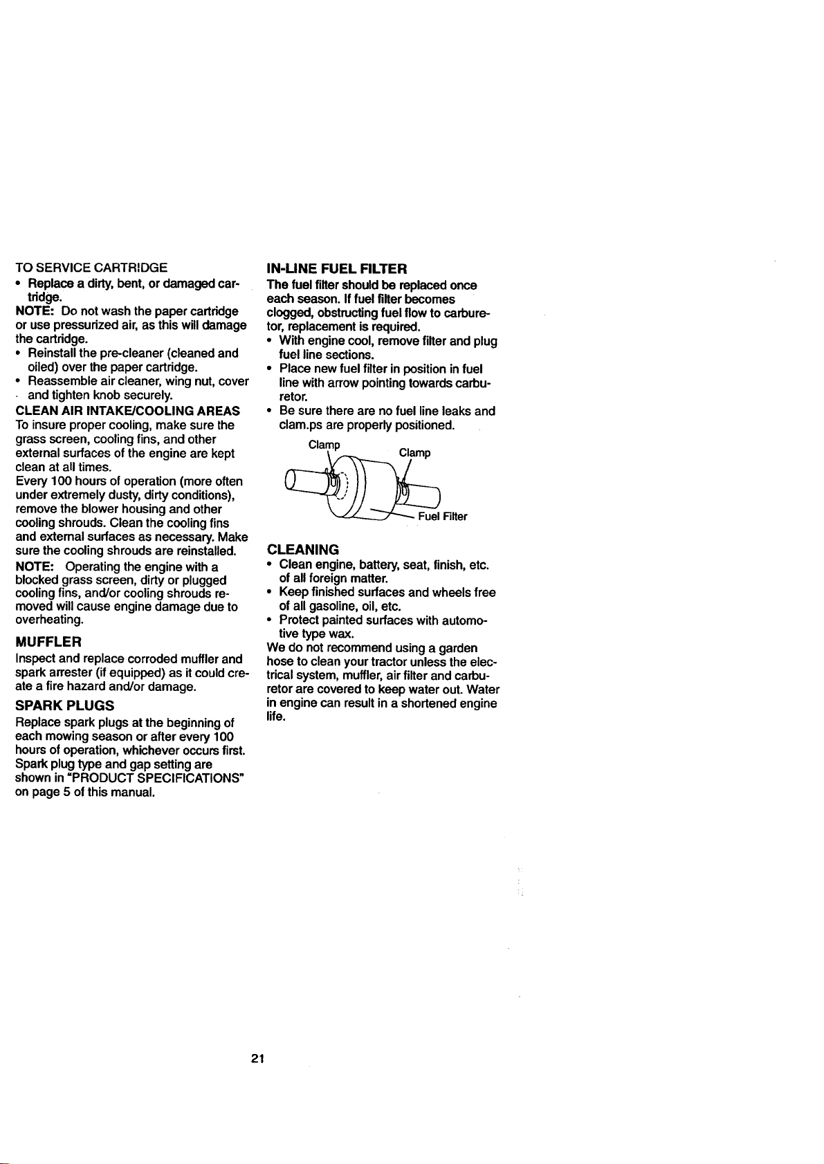
IN-LINE FUEL FILTER
The fuel filtershould be replaced once
each season. If fuel filter becomes
clogged, obstructing fuel flow to carbure-
tor, replacement is required.
• With engine cool, remove filter and plug
fuel line sections.
• Place new fuel filter in position in fuel
line with arrow pointing towards carbu-
retor.
• Be sure there are no fuel line leaks and
clam.ps are properly positioned.
_ Filter
CLEANING
• Clean engine, battery, seat, finish, etc.
of all foreign matter.
• Keep finished surfaces and wheels free
of all gasoline, oil, etc.
• Protect painted surfaces with automo-
tive type wax.
We do not recommend using a garden
hose to clean your tractor unless the elec-
trical system, muffler, air filter and carbu-
retor are covered to keep water out. Water
in engine can result in a shortened engine
life.
21
,_CAUTION: Before pedorming any service or adjustments:
• Depress clutch/brake pedal fullyand set parking brake.
• Place motion control lever in neutral (N) position.
• Place attachment clutch in "DISENGAGED" position.
• Turn ignitionkey "OFF" and remove key.
* Make sure the blades and all moving pads have completely stopped.
• Disconnect spark plug wire from spark plug and place wire where it cannot come
in contact with plug.
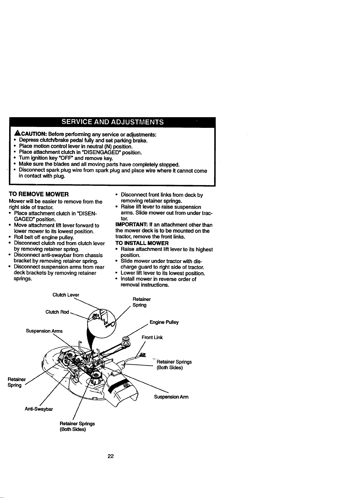
TO REMOVE MOWER
Mowerwillbeeasierto removefromthe
rightsideoftractor.
• Placeattachmentclutchin=DISEN-
GAGED"position.
• Moveattachmentliftleverforwardto
lowermowerto itslowestposition.
• Rollbelt offenginepulley.
• Disconnectclutchrodfrom clutchlever
byremovingretainerspring.
• Disconnectanti-swaybarfrom chassis
bracketbyremovingretainerspring.
• Disconnectsuspensionarmsfrom rear
deckbracketsbyremovingretainer
spdngs.
Clutch Lever
Clutch
Suspension Arms
• Disconnectfrontlinksfromdeckby
removingretainersprings.
• Raiseliftleverto raisesuspension
arms.Slidemoweroutfrom undertrac-
tor.
IMPORTANT:Ifan attachmentotherthan
the mowerdeckistobe mountedonthe
tractor,removethefrontlinks.
TO INSTALLMOWER
• Raiseattachmentliftlevertoitshighest
position.
• Slidemowerundertractorwithdis-
chargeguardtorightsideoftractor.
• Lowerliftlevertoitslowestposition.
• Installmowerin reverseorderof
removalinstructions.
Retainer
Spring
EnginePulley
Front Link
Retainer
Spring
Anti-Swaybar
RetainerSpdngs
(BothSides)
Retainer Springs
(Both Sides)
SuspensionArm
22
TO LEVEL MOWER HOUSING
Adjustthemowerwhiletractorisparked
on levelgroundor driveway. Makesure
tiresare properlyinflated(See =PROD-
UCT SPECIFICATIONS'). Iftiresare
overorunderinflated,youwillnotpropedy
adjustyourmower.
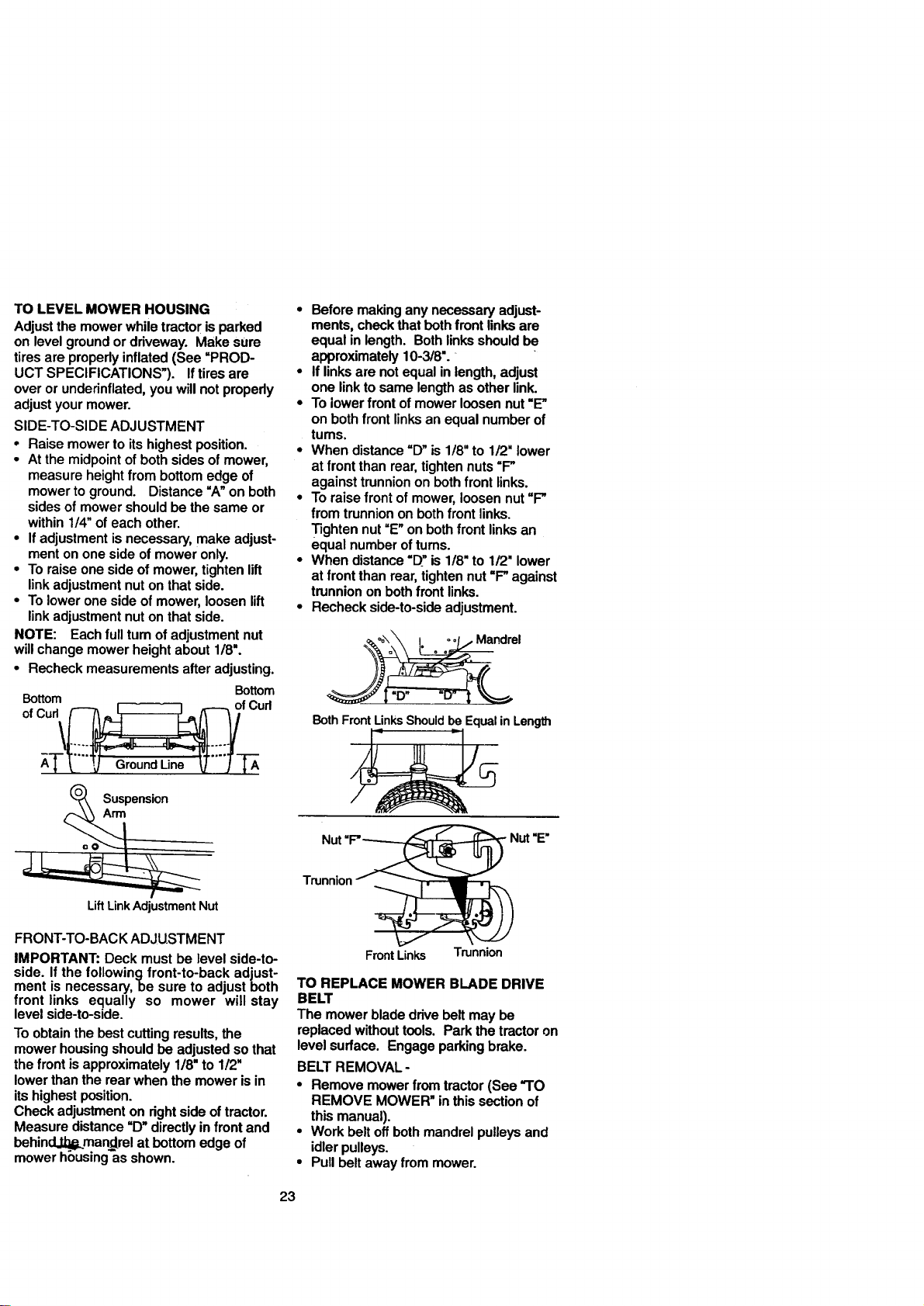
SIDE-TO-SiDEADJUSTMENT
• Raisemowerto itshighestposition.
° Atthemidpointofbothsidesofmower,
measureheightfrom bottomedgeof
mowertoground. Distance=A"on both
sidesofmowershouldbethesame or
within1/4"ofeachother.
• Ifadjustmentisnecessary,makeadjust-
menton onesideofmoweronly.
° Toraiseonesideofmower,tightenlift
linkadjustmentnuton thatside.
° Toloweronesideofmower,loosenlift
linkadjustmentnutonthatside.
NOTE: Eachfull tum ofadjustmentnut
willchangemowerheightabout1/8".
• Recheckmeasurementsafteradjusting.
Bottom
Bottom
ofCud_ f Curt
t- 7GroundLine _--j-r _
(_ Suspension
Lift Link Adjustment Nut
• Beforemakinganynecessaryadjust-
ments,checkthatbothfront linksare
equalin length.Bothlinksshouldbe
approximately10-3/8".
• Iflinksare notequalin length,adjust
one linktosame lengthas otherlink.
• Tolowerfront ofmowerloosennut=E"
on bothfront linksanequalnumberof
tums.
• When distance=D"is 1/8"to 1/2"lower
at front thanrear,tightennuts=P
againsttrunniononbothfront links.
• To raisefront ofmower,loosennut=P
from trunniononbothfront links.
Tightennut=E"onbothfront linksan
equalnumberoftums.
• When distance=D"is 1/8"to 1/2"lower
at front thanrear,tightennut=P against
trunnionon bothfront links.
• Recheckside-to-sideadjustment.
ndrel
BothFrontLinksShouldbe EqualinLength
Trunnion
FRONT-TO-BACKADJUSTMENT
IMPORTANT:Deck mustbe level side-to-
side. Ifthe followingfront-to-back adjust-
mentis necessary,be sureto adjustboth
front links equally so mower will stay
levelside-to-side.
To obtainthe bestcuttingresults,the
mowerhousingshouldbe adjustedsothat
thefront isapproximately1/8"to1/2"
lowerthanthe rearwhenthemowerisin
itshighestposition.
Checkadjustmenton rightside oftractor.
Measuredistance=D"directlyinfront and
behind.,tti_mandrelat bottomedgeof
mowerh_usingasshown.
Front Links Trunnion
TO REPLACE MOWER BLADE DRIVE
BELT
The mower blade drive belt may be
replaced without tools. Park the tractor on
level surface. Engage parking brake.
BELT REMOVAL -
• Remove mower from tractor (See "TO
REMOVE MOWER" in this section of
this manual).
• Work belt off both mandrel pulleys and
idler pulleys.
• Pull belt away from mower.
23
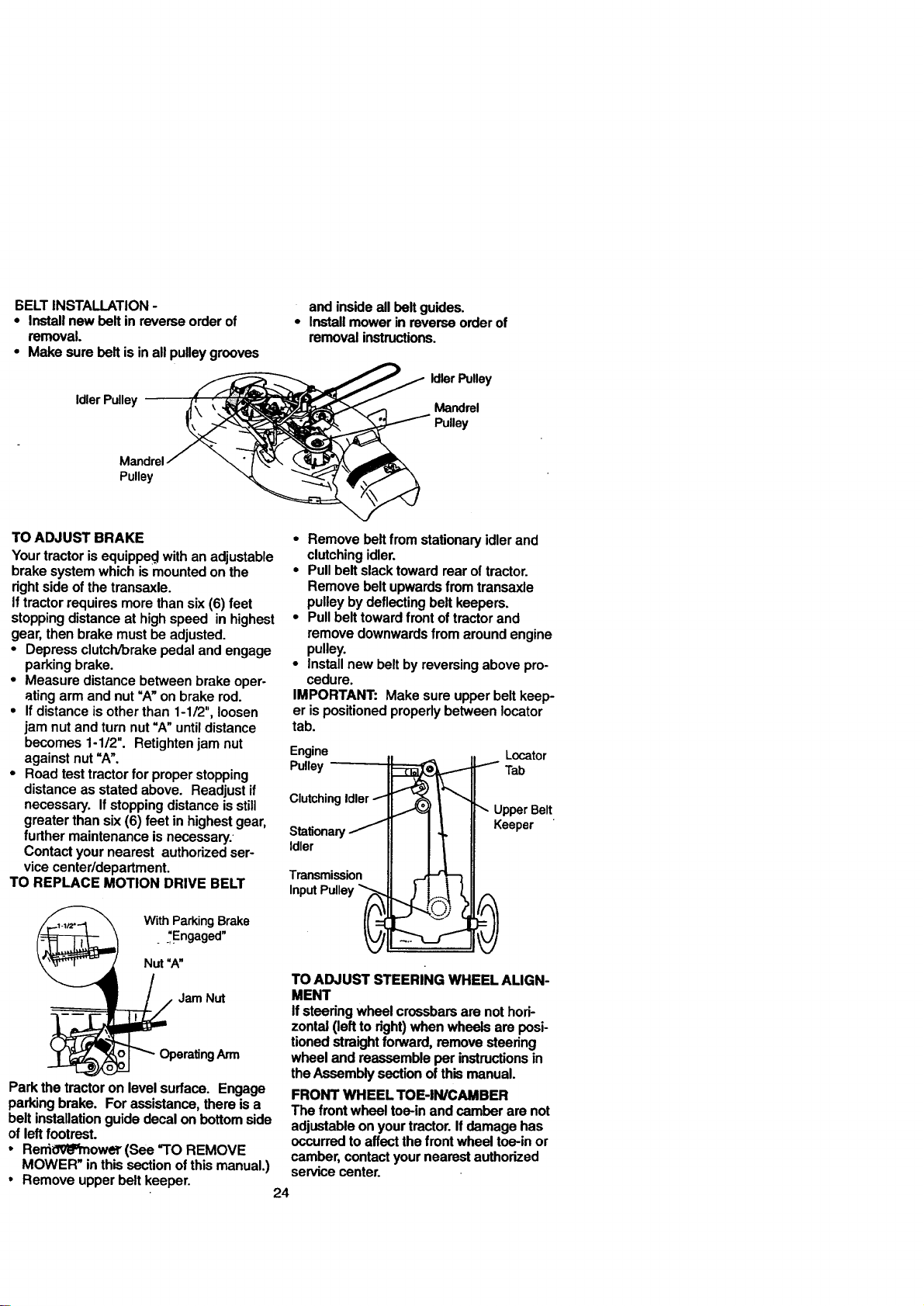
BELTINSTALLATION-
• Install new belt in reverse order of
removal.
• Make sure belt is in all pulley grooves
IdlerPulley
Mandrel
Pulley
and inside all belt guides.
• Install mower in reverse order of
removal instructions.
IdlerPulley
Mandrel
TO ADJUST BRAKE
Your tractor is equippe_ with an adjustable
brake system which is mounted on the
right side of the transaxle.
If tractor requires more than six (6) feet
stopping distance at high speed in highest
gear, then brake must be adjusted.
• Depress clutch/brake pedal and engage
parking brake.
• Measure distance between brake oper-
ating arm and nut =A" on brake rod.
• If distance is other than 1-1/2", loosen
jam nut and turn nut "A" until distance
becomes 1-1/2". Retighten jam nut
against nut =A".
• Road test tractor for proper stopping
distance as stated above. Readjust if
necessary. If stopping distance is still
greater than six (6) feet in highest gear,
further maintenance is necessary.
Contact your nearest authorized ser-
vice center/department.
TO REPLACE MOTION DRIVE BELT
With ParkingBrake
__Engaged"
Nut "A"
• // Jam Nut
Park the tractor on level surface. Engage
parking brake. For assistance, there is a
belt installation guide decal on bottom side
of left footrest.
• RemOV'_rnower (See =TO REMOVE
MOWER" in this section of this manual.)
• Remove upper belt keeper.
• Removebeltfromstationaryidlerand
clutchingidler.
• Pullbeltslacktowardrear oftractor.
Removebeltupwardsfrom transaxle
pulleybydeflectingbelt keepers.
• Pullbelttowardfront oftractorand
removedownwardsfrom aroundengine
pulley.
• Installnewbeltbyreversingabovepro-
cedure.
IMPORTANT: Makesureupperbeltkeep-
er ispositionedproperlybetweenlocator
tab.
Engine
Pulley
Clutching Idler /
Stationary /
Idler
Transmission
Input Pulley _=
Locator
i Tab
UpperBelt
Keeper
)
TO ADJUST STEERING WHEEL ALIGN-
MENT
Ifsteeringwheelcrossbarsare nothori-
zontal(lefttoright)whenwheelsare posi-
tionedstraightforward, removesteering
wheeland reassembleper instructionsin
theAssemblysectionofthismanual.
FRONT WHEEL TOE-IN/CAMBER
The front wheeltoe-inand camberarenot
adjustableon yourtractor.Ifdamagehas
occurredtoaffectthefrontwheeltoe-inor
camber,contactyournearestauthorized
servicecenter.
24
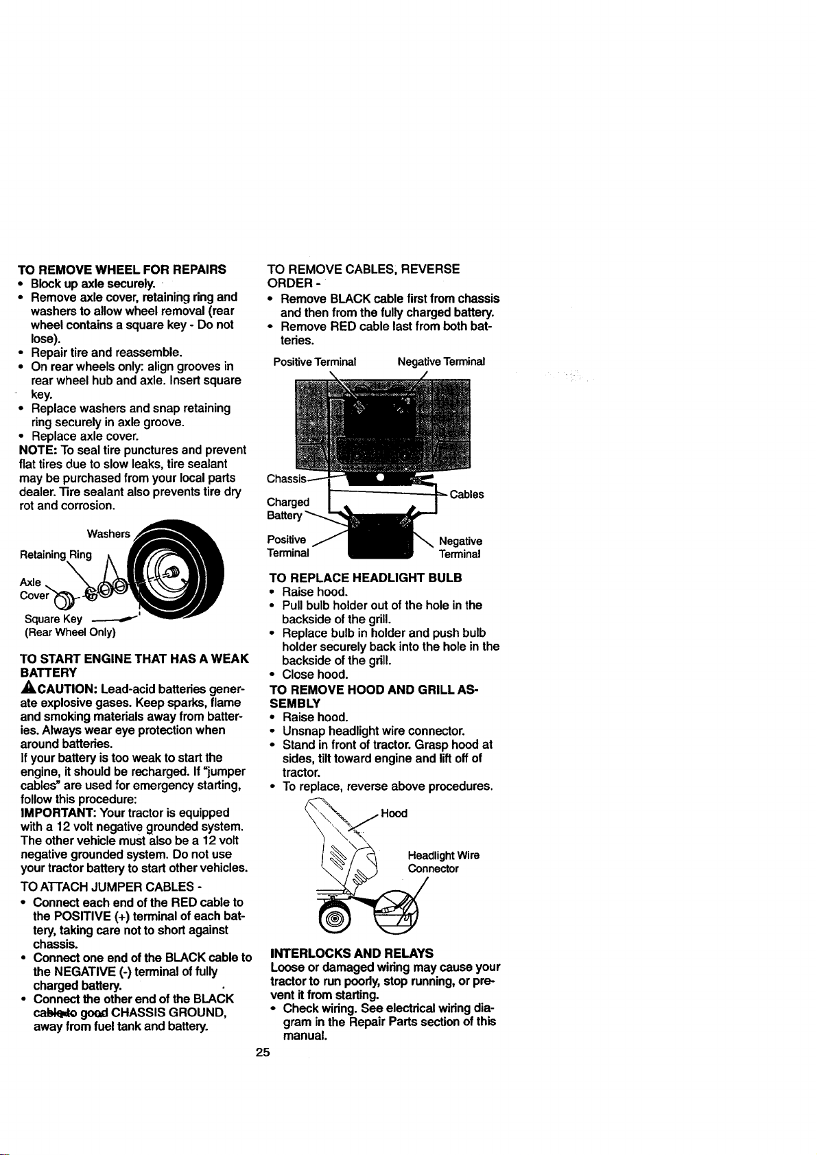
TOREMOVEWHEELFORREPAIRS
• Block up axle securely.
• Remove axle cover, retaining ring and
washers to allow wheel removal (rear
wheel contains a square key - Do not
lose).
• Repair tire and reassemble.
• On rear wheels only: align grooves in
rear wheel hub and axle. Insert square
key.
• Replace washers and snap retaining
ring securely in axle groove.
• Replace axle cover.
NOTE: To seal tire punctures and prevent
flat tires due to slow leaks, tire sealant
may be purchased from your local parts
dealer. 13re sealant also prevents tire dry
rot and corrosion.
WashersA
RetainingRing _ ff/'__
SquareKey _' "_'_"
(Rear Wheel Only)
TO START ENGINE THAT HAS A WEAK
BATTERY
_CAUTION: Lead-acid batteries gener-
ate explosive gases. Keep sparks, flame
and smoking materials away from batter-
ies. Always wear eye protection when
around batteries.
If your battery is too weak to start the
engine, it should be recharged. If "jumper
cables" are used for emergency starting,
follow this procedure:
IMPORTANT: Your tractor is equipped
with a 12 volt negativ e grounded system.
The other vehicle must also be a 12 volt
negative grounded system. Do not use
your tractor battery to start other vehicles.
TO ATTACH JUMPER CABLES -
• Connect each end of the RED cable to
the POSITIVE (+) terminal of each bat-
tery, taking care not to short against
chassis.
• Connect one end of the BLACK cable to
the NEGATIVE (-) terminal of fully
charged battery.
• Connect the other end of the BLACK
cabk_to goed CHASSIS GROUND,
away from fuel tank and battery.
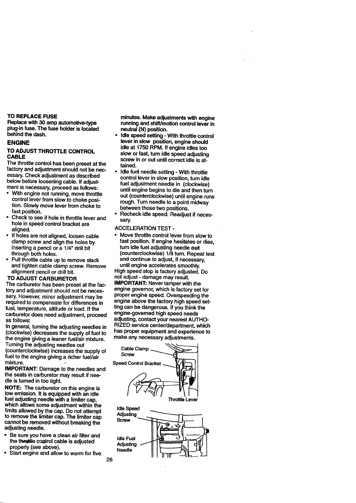
TO REMOVE CABLES, REVERSE
ORDER -
• Remove BLACK cable first from chassis
and then from the fully charged battery.
- Remove RED cable last from both bat-
tedes.
Positive Terminal
NegativeTerminal
Charged
Ballet
Positive Negative
Terminal Terminal
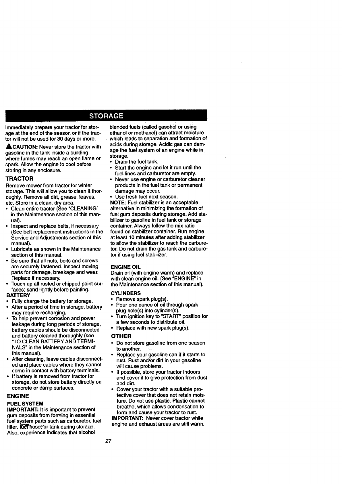
TO REPLACE HEADLIGHT BULB
• Raise hood.
• Pull bulb holder out of the hole in the
backside of the grill.
• Replace bulb in holder and push bulb
holder securely back into the hole in the
backside of the gdll.
• Close hood.
TO REMOVE HOOD AND GRILL AS-
SEMBLY
• Raise hood.
• Unsnap headlight wire connector.
• Stand in front oftractor. Grasp hood at
sides, tilt toward engine and liftoff of
tractor.
• To replace, reverse above procedures.
\
Headlight Wire
Connector
INTERLOCKS AND RELAYS
Loose or damaged wiring may cause your
tractor to run poody, stop running, or pre-
vent itfrom starting.
• Check wiring. See electrical widng dia-
gram in the Repair Parts section of this
manual.
25
TOREPLACEFUSE
Replacewith30ampautomotive-type
plug-infuse.Thefuseholderislocated
behindthedash.
ENGINE
TO ADJUST THROI"FLE CONTROL
CABLE
The throttlecontrol has been preset at the
factory and adjustment should notbe nec-
essary. Check adjustment as described
below before loosening cable. If adjust-
ment is necessary, proceed as follows:
• With engine not running, move throttle
control lever from slow to choke posi-
tion. Slowly move lever from choke to
fast position.
• Check to see if hole in throttle lever and
hole in speed control bracket are
aligned.
• If holes are not aligned, loosen cable
clamp screw and align the holes by
inserting a pencil or a 1/4" ddll bit
through both holes.
• Pull throttle cable up to remove slack
and tighten cable clamp screw. Remove
alignment pencil or drill bit.
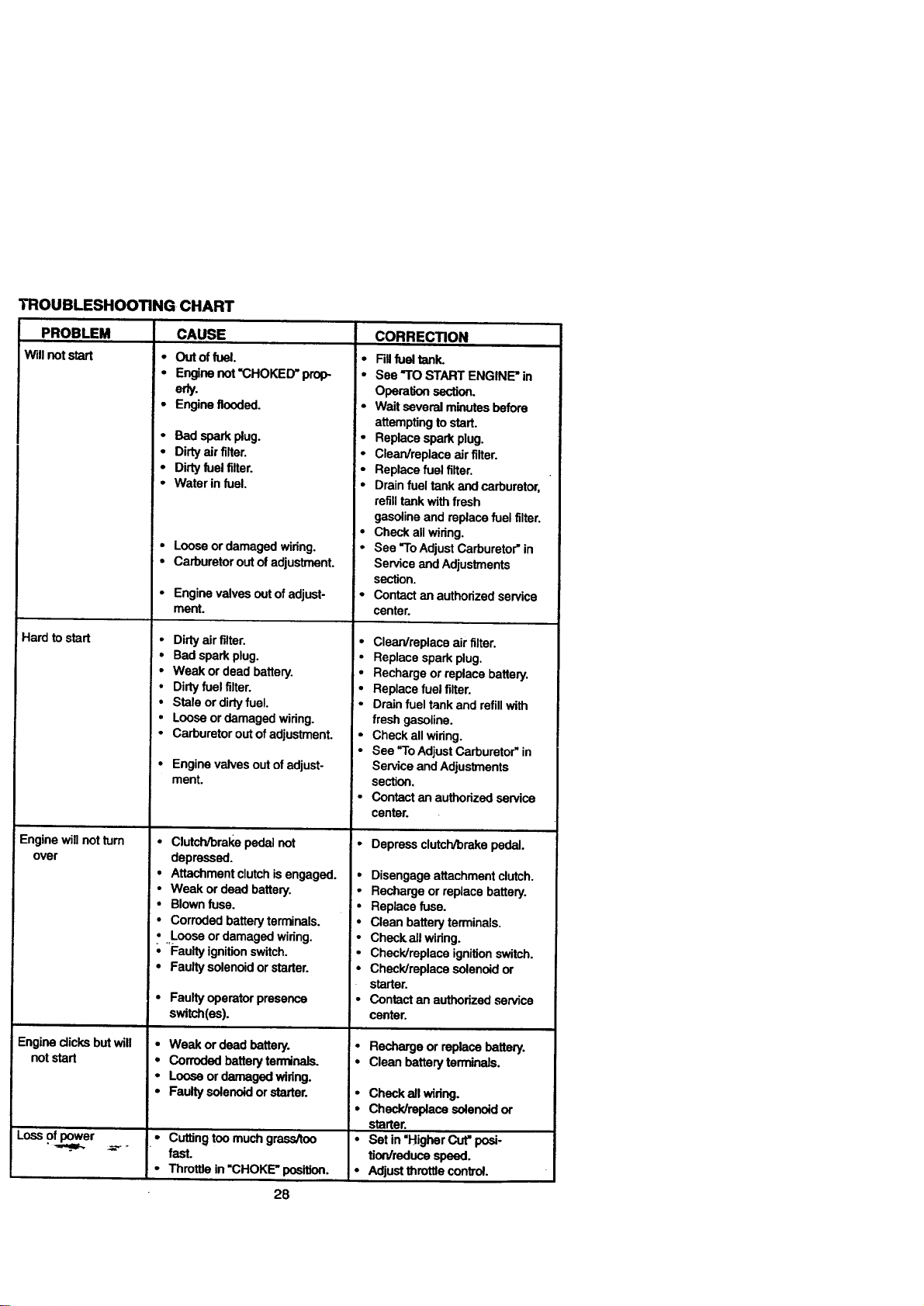
TO ADJUST CARBURETOR
The carburetor has been preset at the fac-
tory and adjustment should not be neces-
sary. However, minor adjustment may be
required to compensate for differences in
fuel, temperature, altitude or load. If the
carburetor does need adjustment, proceed
as follows:
In general, turning the adjusting needles in
(clockwise) decreases the supply of fuel to
the engine giving a leaner fueVair mixture.
Turning the adjusting needles out
(counterclockwise) increases the supply of
fuel to the engine giving a richer fueVair
mixture. -,
IMPORTANT: Damage tothe needlesand
the seatsincarburetormay resultifnee-
dleisturnedintootight.
NOTE: The carburetoron thisengineis
low emission.Itisequippedwithan idle
fueladjustingneedlewitha limitercap,
which allowssome adjustmentwithinthe
limitsallowedby thecap.Do notattempt
toremove the limitercap.The limitercap
cannotbe removed withoutbreakingthe
adjustingneedle.
• Be sure you have a clean air filter and
the tl=vr_ttecontrol cable is adjusted
properly (see above).
• Start engine and allow to warm for five
minutes. Make adjustments with engine
running and shift/motion control lever in
neutral (N) position.
• Idle speed setting - With throttle control
lever in slow position, engine should
idle at 1750 RPM. If engine idles too
slow or fast, turn idle speed adjusting
screw in or out until correct idle is at-
tained.
• Idle fuel needle setting - With throttle
control lever in slow position, turn idle
fuel adjustment needle in (clockwise)
until engine begins to die and then turn
out (counterclockwise) until engine runs
rough. Tum needle to a pointmidway
between those two positions.
• Recheck idle speed. Readjust if neces-
sary.
ACCELERATION TEST -
• Move throttle control lever from slow to
fast position. If engine hesitates or dies,
turn idle fuel adjusting needle out
(counterclockwise) 1/8 rum. Repeat test
and continue to adjust, if necessary,
until engine accelerates smoothly.
High speed stop is factory adjusted. Do
not adjust - damage may result.
IMPORTANT: Never tamper with the
engine governor, which is factory set for
proper engine speed. Overspeeding the
engine above the factory high speed set-
ting can be dangerous. If you think the
engine-governed high speed needs
adjusting, contact your nearest AUTHO-
RIZED service center/department, which
has proper equipment and experience to
make any necessary adjustments.
CableClamp
Screw
SpeedControlBracket
Idle Speed
Adjusting
Screw
ThrottleLever
Idle Fuel
AdjuslJng
Needle
26
Immediatelyprepareyourtractorforstor-
ageat theend ofthe seasonor ifthetrac-
torwillnotbeusedfor 30 daysor more.
_CAUTION: Neverstorethetractorwith
gasolineinthetankinsidea building
wherefumesmay reachanopenflameor
spark. Allowthe enginetocoolbefore
storinginanyenclosure.
TRACTOR
Removemowerfrom tractorfor winter
storage.Thiswillallowyoutoclean itthor-
oughly.Removeall dirt,grease,leaves,
etc.Storeina clean,dryarea.
• Cleanentiretractor(See "CLEANING"
intheMaintenancesectionofthisman-
ual).
• Inspectand replacebelts,ifnecessary
(See beltreplacementinstructionsinthe
ServiceandAdjustmentssectionofthis
manual).
• Lubricateas showninthe Maintenance
sectionofthismanual.
• Be surethatall nuts,boltsandscrews
are securelyfastened.Inspectmoving
partsfordamage,breakageandwear.
Replaceifnecessary.
• Touchup allrustedor chippedpaintsur-
faces; sandlightlybeforepainting.
BATTERY
• Fullychargethebatteryforstorage.
• After a periodoftimeinstorage,battery
may requirerecharging.
• To helppreventcorrosionand power
leakageduringlongperiodsofstorage,
batterycablesshouldbedisconnected
and batterycleanedthoroughly(see
=-I0 CLEAN BATTERYANDTERMI-
NALS"intheMaintenancesectionof
thismanual).
• Aftercleaning,leavecablesdisconnect-
ed and placecableswheretheycannot
comeincontactwithbatteryterminals.
• Ifbatteryisremovedfrom tractorfor
storage,donotstorebatterydirectlyon
concreteordampsurfaces.
ENGINE
FUEL SYSTEM
IMPORTANT: It is important to prevent
gum deposits from forming in essential
fuel system parts such as carburetor, fuel
filter, _ose,_or tank duringstorage.
Also, experience indicates that alcohol
blendedfuels(calledgasohoior using
ethanolor methanol)canattractmoisture
whichleadstoseparationand formationof
acidsduringstorage.Acidicgascan dam-
agethefuel systemofan enginewhilein
storage.
• Drainthefuel tank.
• Startthe engineandletitrununtilthe
fuellinesand carburetorareempty.
• Never useengineorcarburetorcleaner
productsin thefueltankorpermanent
damagemay occur.
• Usefresh fuel nextseason.
NOTE: Fuelstabilizerisan acceptable
alternativeinminimizingthe formation of
fuel gumdepositsduringstorage.Addsta-
bilizerto gasolineinfuel tankorstorage
container.Alwaysfollow themixratio
found onstabilizercontainer.Runengine
at least10 minutesafteraddingstabilizer
toallowthestabilizertoreachthe carbure-
tor.Do notdrainthe gastankandcarbure-
torifusingfuel stabilizer.
ENGINE OIL
Drainoil(withenginewarm)and replace
withcleanengineoil. (See "ENGINE"in
the Maintenancesectionofthismanual).
CYLINDERS
• Removesparkplug(s).
• Pour one ounceofoilthroughspark
plughole(s)intocylinder(s).
• Turnignitionkeyto=START"positionfor
a few secondstodistributeoil.
• Replacewithnewsparkplug(s).
OTHER
• Do notstoregasolinefrom one season
toanother. ....
• Replaceyourgasolinecanifitstartsto
rust.Rustand/ordirtinyourgasoline
willcauseproblems.
• Ifpossible,storeyourtractorindoors
and coverittogiveprotectionfrom dust
anddirt.
• Coveryourtractorwitha suitablepro-
tectivecoverthatdoesnotretainmois-
ture. Do notuseplastic.Plasticcannot
breathe,whichallowscondensationto
formand causeyourtractortorust.
IMPORTANT: Nevercovertractorwhile
engineandexhaustareasarestillwarm.
27
TROUBLESHOOTING CHART
PROBLEM CAUSE CORRECTION
Will not start
Hard to start
Engine wi, not turn
over
Engine dicks but will
not start
Loss Of power
• Out of fuel.
• Engine not'CHOKED" prop
e_.
• Engine flooded.
• Bad spark plug.
• Dirty air filter.
• Dirty fuel filter.
• Water in fuel.
• Loose or damaged wiring.
• Carburetor out of adjustment.
• Engine valves out of adjust-
ment.
• Dirty air filter.
• Bad spark plug.
• Weak or dead battery.
• Dirty fuelfilter.
• Stale or dirty fuel.
• Loose or damaged wiring.
• Carburetor out of adjustment.
• Engine valves out of adjust-
ment.
• Clutch/brake pedal not
depressed.
• Attachment clutch is engaged.
• Weak or dead battery.
• Blown fuse.
• Corroded battery terminals.
• _,.Looseor damaged wiring.
• Faulty ignition switch.
• Faulty solenoid or starter.
• Faulty operator presence
switch(es).
• Weak or dead battery.
• Corroded battery terminals.
• Loose or damaged wiring.
• Faulty solenoid or starter.
• Cuffing too much grass/too
fast.
• Throttle in "CHOKE" position.
• Figfuel tank.
• See "TOSTARTENGINE"in
Operationsection.
• Waitseveral minutesbefore
attemptingtostart.
• Replacesparkplug.
• Clean/replaceair filter.
• Replacefuelfilter.
• Drainfueltank andcarburetor,
refilltankwithfresh
gasolineand replacefuel filter.
• Checkallwiring.
• See "ToAdjustCarburetor"in
ServiceandAdjustments
section.
• Contact an authorizedservice
center.
• Clean/replace air filter.
• Replace spark plug.
• Recharge or replace battery.
• Replace fuel filter.
• Drain fuel tank and refill with
fresh gasoline.
• Check all wiring.
• See "ToAdjust Carburetor" in
Service and Adjustments
section.
• Contact an authorized service
center.
Depressclutch/brakepedal.
• Disengageattachmentclutch.
• Rechargeor replacebattery.
• Replacefuse.
• Cleanbatteryterminals.
• Checkail widng.
• Check/replaceignitionswitch.
• Check/replacesolenoid or
starter.
• Contact an authorizedservice
center.
• Rechargeor replacebattery.
• Cleanbatteryterminals.
• Check all wiring.
• Check/replace solenoid or
starter.
• Set in "Higher Cut" posi-
tion/reduce speed.
• Adjust throttle control.
28
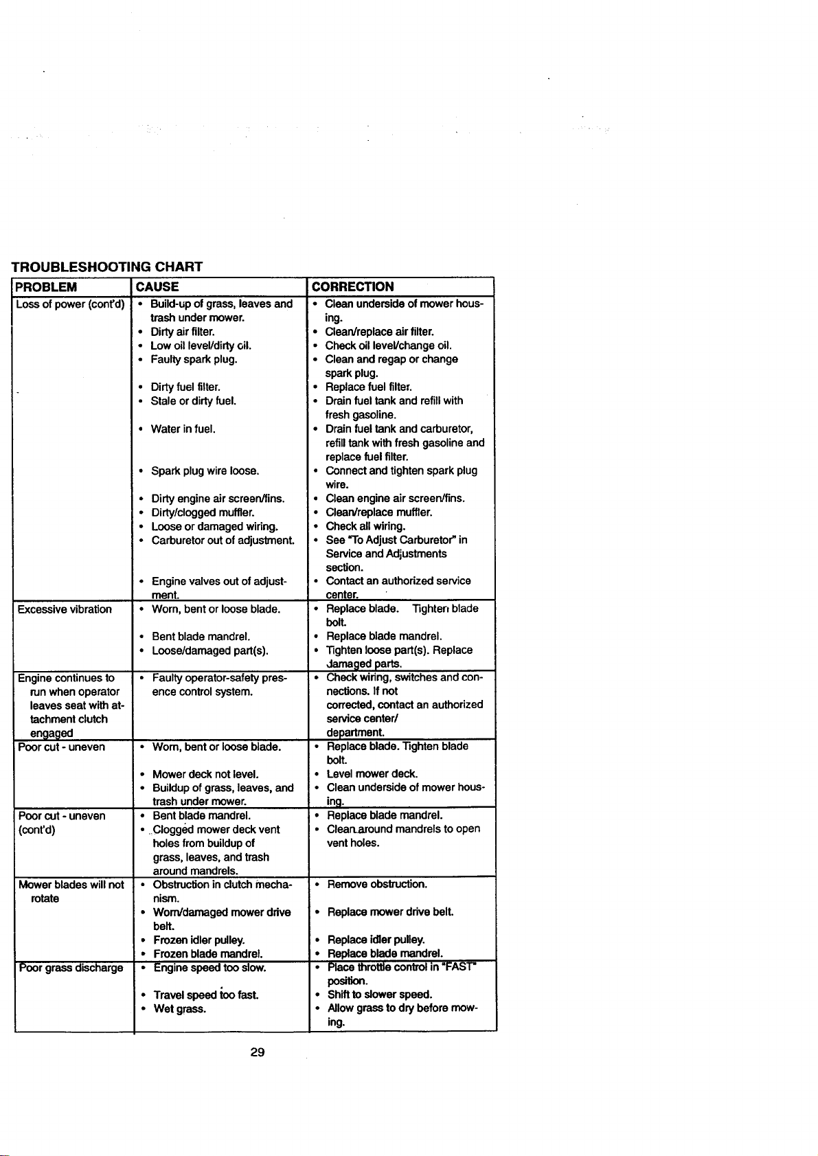
PROBLEM
Loseofpower(cont'd)
TROUBLESHOOTING CHART
CAUSE
• Build-up of grass, leaves and
trash under mower.
• Dirty air filter.
• Low oil level/dirty oil.
• Faulty spark plug.
• Dirty fuel filter.
• Stale or dirty fuel.
• Water in fuel.
• Spark plug wire loose.
Excessivevibration
Engine continues to
run when operator
leaves seat with at-
tachment clutch
engaged
Poor cut - uneven
Poorcut- uneven
(conrd)
Mower blades will not
rotate
Poor grass discharge
• Dirty engine air screen/fins.
• Dirty/clogged muffler.
• Loose or damaged wiring.
• Carburetor out of adjustment.
• Engine valves out of adjust-
ment.
• Worn, bent or loose blade.
• Bentblademandrel.
• Loose/damagedpart(s).
• Faultyoperator-safetypres-
ence controlsystem.
• Worn, bent or loose blade.
Mower deck not level.
Buildup of grass, leaves, and
trash under mower.
Bent blade mandrel.
Clogged mower deck vent
holes from buildup of
grass, leaves, and trash
around mandrels.
Obstruction in clutch mecha-
nism.
Worn/damaged mower drive
belt.
Frozen idler pulley.
Frozen blade mandrel.
Engine speed too slow.
Travelspeedtoo fast.
Wet grass.
CORRECTION
• Clean underside of mower hous-
ing.
• Clean/replace air filter.
• Check oil level/change oil.
• Clean and regap or change
spark plug.
• Replace fuel filter.
• Drain fuel tank and refillwith
fresh gasoline.
• Drain fuel tank and carburetor,
refilltank with fresh gasoline and
replace fuel filter.
• Connect and tighten spark plug
wire.
• Clean engine air screen/fins.
• Clean/replace muffler.
• Check all wiring.
• See =ToAdjust Carburetor" in
Service and Adjustments
section.
• Contact an authorized service
center.
• Replace blade. Tighten blade
bolt.
• Replace blade mandrel.
• Tighten loose part(s). Replace
Jama_led parts.
• Check wiring, switches and con-
nections. If not
corrected, contact an authorized
service center/
department.
• Replace blade. Tighten blade
bolt.
• Level mower deck.
• Clean underside of mower hous-
ing.
• Replace blade mandrel.
• Clean.mound mandrels toopen
vent holes.
• Remove obstruction.
• Replace mower drive belt.
• Replace idler pulley.
• Replace blade mandrel.
• Place throttle control in "FAST"
positS.
• Shift to dower speed.
• Allow grass to dry before mow-
ing.
29
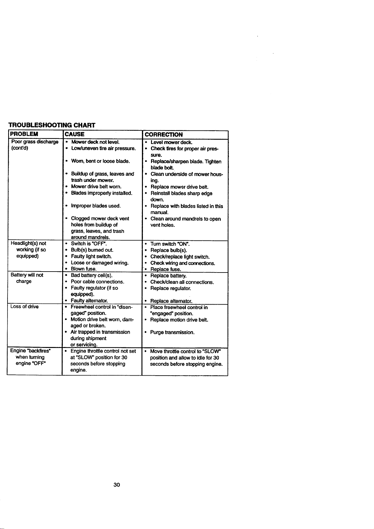
TROUBLESHOOTING CHART
PROBLEM CAUSE
Poor grass discharge • Mower deck not level.
(cont'd) • Low/uneven tire air pressure.
Headlight(s)not
working(ifso
equipped)
Batterywillnot
charge
Lossofdrive
Engine=backfires"
whenfuming
engine"OFF"
• Worn, bent or loose blade.
• Buildup of grass, leaves and
trash under mower.
• Mower drive belt worn.
• Blades impropedy installed.
• Improper blades used.
• Clogged mower deck vent
holes from buildup of
grass, leaves, and trash
around mandrels.
• Switch is "OFF".
• Bulb(s) burned ouL
• Faulty lightswitch.
• Loose or damaged wiring.
• Blown fuse.
• Bad battery cell(s).
• Poor cable connections.
• Faulty regulator (if so
I" equipped).
Faulty alternator.
• Freewheel control in =disen-
gaged" position.
• Motion drive belt worn, dam-
aged or broken.
• Air trapped in transmission
during shipment
or servicing.
• Engine throttle control not set
at "SLOW" position for 30
seconds before stopping
engine.
CORRECTION
• Level mower deck,
• Check tires for proper air pres-
sure.
• Replace/sharpen blade. "i3ghten
blade boll
• Clean underside of mower hous-
ing.
• Replace mower drive bait.
• Reinstall blades sharp edge
down.
• Replace with blades listed in this
manual.
• Clean around mandrels to open
vent holes.
• Tum switch "ON'.
• Replace bulb(s).
• Check/replace lightswitch.
• Check widng and connections.
• Replace fuse.
• Replace battery.
• Check/clean all connections.
• Replace regulator.
i • Replace aitemator.
• Place freewheel control in
=engaged" position.
• Replace motion drive belt.
• Purge transmission.
• Movethrottlecontrol to=SLOW"
positionand allowtoidlefor 30
secondsbeforestoppingengine.
3O
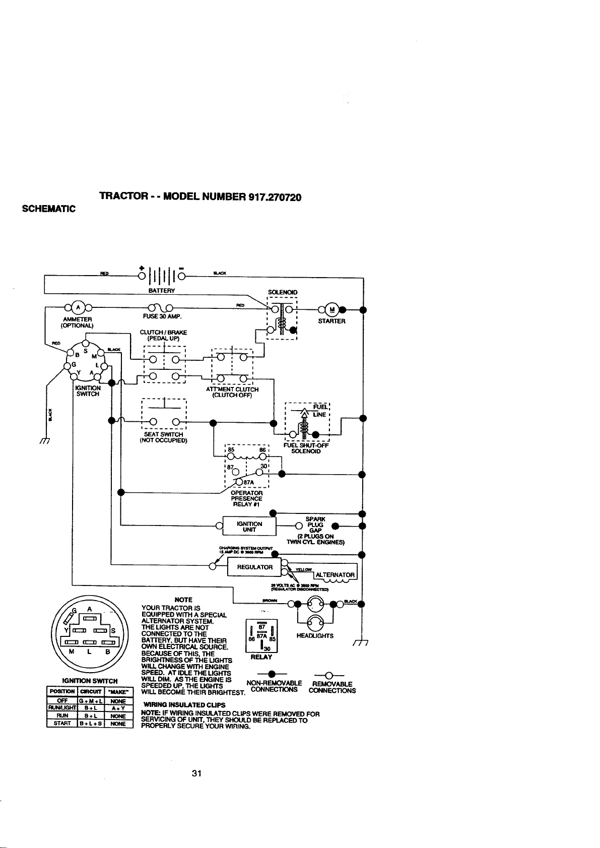
SCHEMATIC
TRACTOR - - MODEL NUMBER 917.270720
[
m_p
AMMETER
(OPTIONAL)
IGNITION
SWITCH
BAI-rERY SOLENOID
FUSE30 AMP. _ _ ' =TAD'n_"_ a
I ,,PED_.UP) • ......
I :---_---_ _-_:-_-,-]
! I i P
ATT'MENTCLUTCH I
• (CLUTCHOFF) I
:l-: f :-,,,___'.
D t I J ",_' LINE D
i ! A I i
o: r, €,_ , I---_
(NOTOCCUPIED) / ,- ....... , F'U_:L-_J¥-_-F
SOLENOID
• .>'_,_;;;o_-'
• PRESENCE
RELAY#1
A
T-o
IGNITION
u.rr _
IGNITION SWITCH
NO,E I
YOUR TRACTOR IS
EQUIPPED WITH A SPECIAL
ALTERNATOR SYSTEM.
THE LIGHTS ARE NOT
CONNECTED 3"0THE
BATI'ERY, BUT HAVE THEIR
OWN ELECTRICAL SOURCE.
BECAUSE OF THIS, THE
BRIGHTNESS OF THE UGHTS
WILL CHANGE WITH ENGINE
SPEED. AT IDLE THE MGHTS
W1LLDIM. ASTHE ENGINE IS
SPEEDED UP, THE LIGHTS
RELAY
NON-REMOVABLE REMOVABLE
CONNECTIONS CONNECTIONS
WILL BECOME THEIR BRIGHTEST.
WIRING INSULATED CUPS
NOTE: IF WIRING INSULATED CLIPS WERE REMOVED FOR
SERVICING OF UNIT, THEY SHOULD BE REPLACED TO
PROPERLY SECURE YOUR WIRING.
31
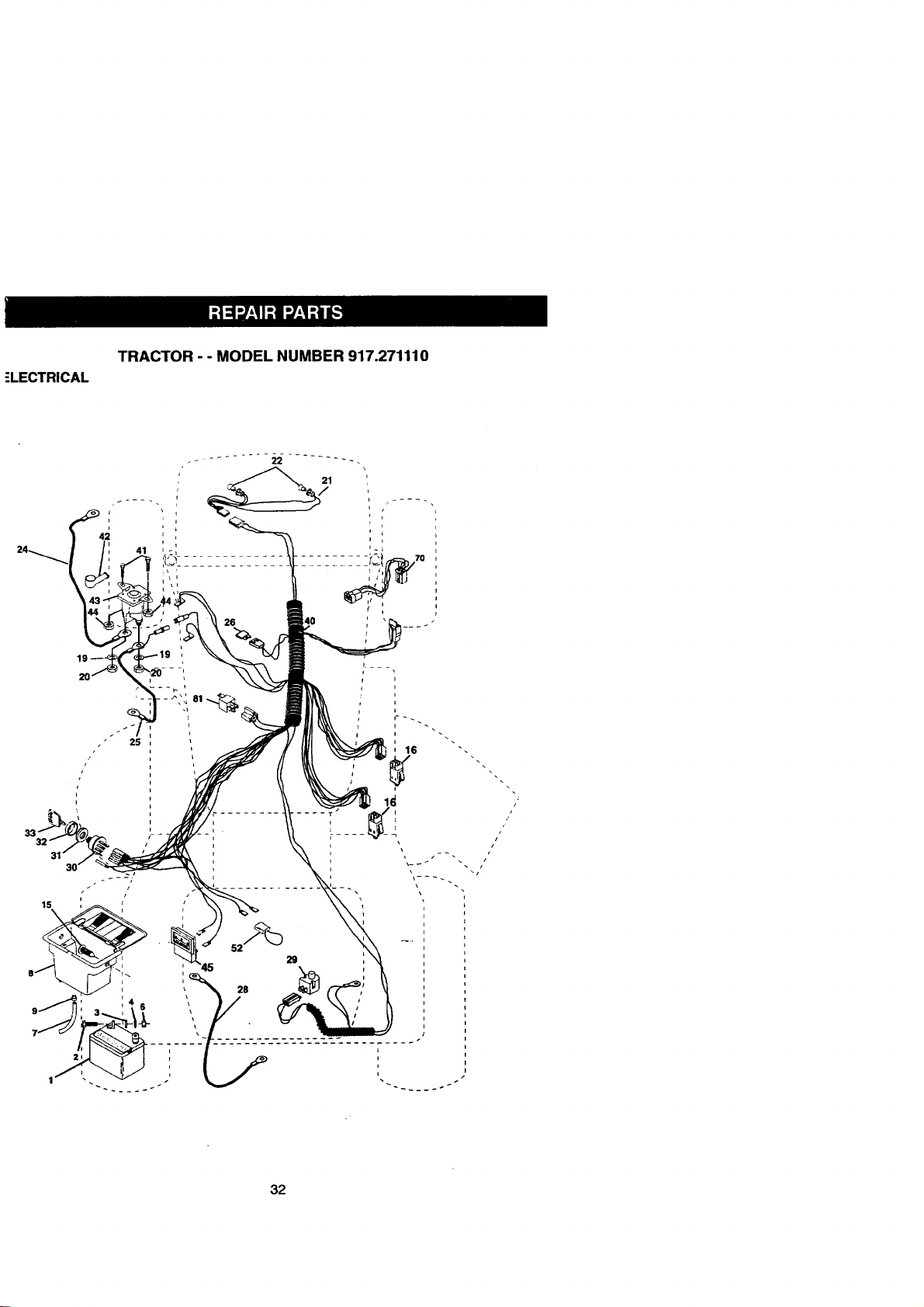
ELECTRICAL
TRACTOR - - MODEL NUMBER 917.271110
i
\
i
i
/
i
s
i
i
/
32
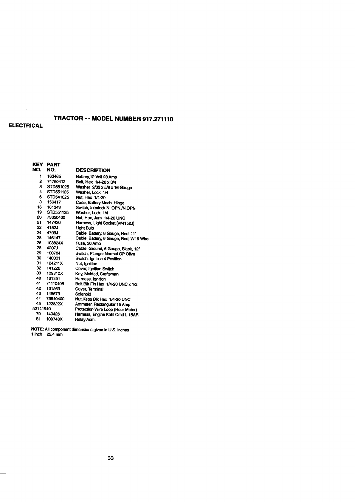
ELECTRICAL
TRACTOR - - MODEL NUMBER 917.271110
KEY PART
NO. NO. DESCRIPTION
1 163465 Battery,12 Volt 28 Amp
2 74760412 Bolt, Hex 114-20 x 3/4
3 STD551025 Washer 9/32 x 5/8 x 16 Gauge
4 STD551125 Washer, Lock 1/4
6 STD541025 Nut, Hex 114-20
8 156417 Case, Battery Mech Hinge
16 161343 Switch, Interlock N. OPNJN.OPN
19 STD551125 Washer, Lock 1/4
20 733504(X) Nut, He,x, Jam 114-20 UNC
21 147430 Harness, Light Socket (w/4152J)
22 4152J Light Bulb
24 4799J Cable, Battery, 6 Gauge, Red, 11'
25 146147 Cable, Battery, 6 Gauge, Red, W16 Wire
26 108824X Fuse, 30 Amp
28 4207J Cable, Ground, 6 Gauge, Black, 12"
29 160784 Switch, Plunger Normal OP Olive
30 140301 Switch, Ignition 4 Position
31 124211X Nut, Ignition
32 141226 Cover, Ignition Switch
33 109310X Key, Molded, Craftsman
40 161351 Harness, IgnllJon
41 71110408 BoltBIkFinHex l/4-20UNCx1/2
42 131563 Cover, Terminal
43 145673 Solenoid
44 73640400 Nut,Keps BIk Hex 1/4-20 UNC
45 122822X Ammeter, Rectangular15 Amp
52141940 Protection Wire Loop (Hour Meter)
70 140426 Harness, Engine Kohl Cmd-L 15AR
81 109748X Relay Asm.
NOTE: All component dimensions given _nU.S. inches
1 inch = 25.4 mm
33
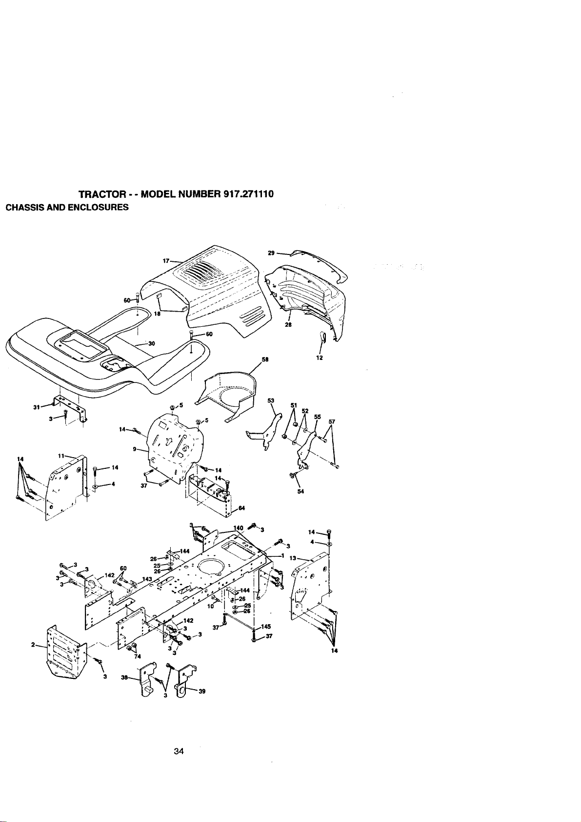
TRACTOR - - MODEL NUMBER 917.271110
CHASSIS AND ENCLOSURES
I
28
58 12
53
\ _1 52 55
54
_13 3 60 25
34
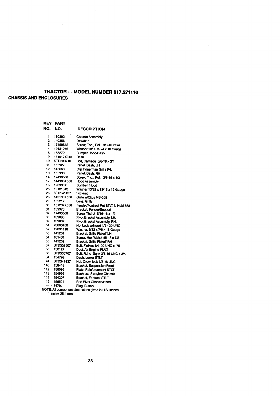
TRACTOR -- MODEL NUMBER 917.271110
CHASSIS AND ENCLOSURES
KEY PART
NO. NO. DESCRIPTION
1 160392 ChassisAssemUy
2 140356 Drawbar
3 17490612 Screw, Thd.,Roll. 3/8-16x3/4
4 19131216 Washer 13/32 x 3/4 x 16 Gauge
5 155272 Bumper Hood/Dash
9 161917X013 Dash
10 STD533710 Bolt, Carriage 3/8-16x3/4
11 155927 Panel, Dash, LH
12 145660 Clip]',merman Gd]le P4.
13 155936 Panel, Dash, RH
14 17490608 Screw, Thd.,Roll. 3/8-16xl/2
17 144983X558 Hood Assembly
18 126938X Bumber Hood
25 19131312 Washer 13/32 x 13/16 x 12 Gauge
26 STD541437 Locknut
26 145198X558 Grille w/Clips MS-558
29 155217 Lens, Gdlle
30 151287X558 Fender/FootrestPntSTLTNHold558
31 139976 Bracket, FendedSupport
37 17490508 ScrewThdrol 5/16-18x 1/2
38 139886 Pivot Bracket Assembly, LH,
39 139887 Pivot Bracket Assembly, PJ-I,
51 73800400 Nut Lock w/Insert 1/4 - 20 UNC
52 19091416 Washer, 9/32 x 7/8 x 16 Gauge
53 145201 Bracket, Gdlle Pickoff LH
54 161464 Screw, HexWshd #8-18x7/8
55 145202 Bracket, Grille Pickoff RH
57 STD552507 Bolt, FinHex 1/4 -_'20UNC x .75
53 150127 Duct, Air Engine PL/LT
60 STD533707 Bolt, Fldhd Sqnk 3/8-16 UNC x 3/4
64 154798 Dash, Lower STLT
74 STD541437 Nut, Crownlock 3/8-16 UNC
140 158418 Bracket, Suspension Front
142 156095 Plate, Reinforcement STLT
143 154966 Backrest, Swaybar Chassis
144 154207 Bracket, Footrest STLT
145 156524 Rod Pivot Chassis/Hood
.... 5479,.I Plug, Button
NOTE: All component dimensions given in U.S, inches
1 inch = 25.4 mm
35
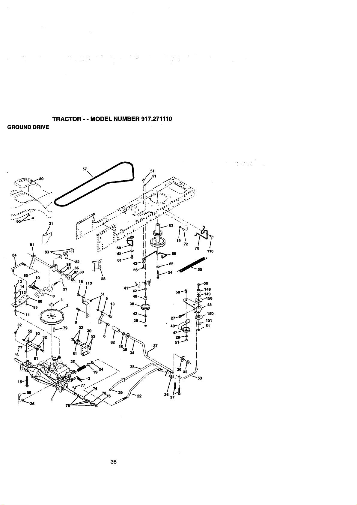
TRACTOR - - MODEL NUMBER 917.271110
GROUND DRIVE
36
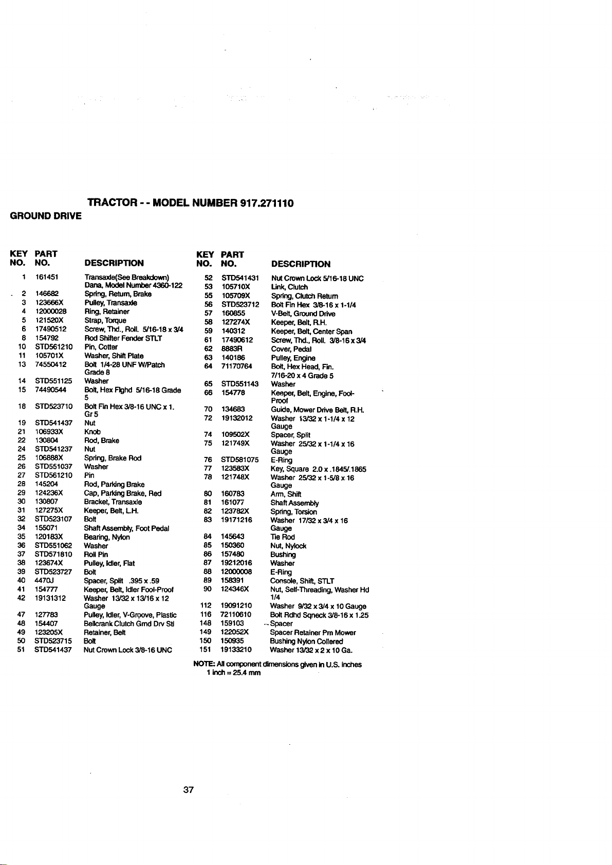
TRACTOR -- MODEL NUMBER 917.271110
GROUND DRIVE
KEY PART KEY PART
NO. NO. DESCRIPTION NO. NO.
1 161451 Transaxle(See Breakdown) 52 STD541431
Dana, Model Number4360-122 53 105710X
2 146682 Spdng, Return, Brake 55 105709X
3 123666X Pulley, Transaxle 56 STD523712
4 12000028 Ring, Retainer 57 160855
5 121520X Strap, Torque 58 127274X
6 17490512 Screw, Thd.,Rolt. 5/16-18x3/4 59 140312
8 154792 Rod Shifter Fender STLT 61 17490612
10 STD561210 Pin, Cotter 62 8883R
11 105701X Washer, Shift Plate 63 140186
13 74550412 Bolt 1/4-28 UNF W/Patch 64 71170764
Grade 8
14 STD551125 Washer 65 STD551143
15 74490544 Bolt, Hex Flghd 5/16-18 Grade 66 154778
5
18 STD523710 Bolt Fin Hex3/8-16 UNC x 1. 70 134683
Gr5 72 19132012
19 STD541437 Nut
21 106933X Knob 74 109502X
22 130804 Rod, Brake 75 121749X
24 STD541237 Nut
25 106888X Spdng, Brake Rod 76 STD581075
26 STD551037 Washer 77 123583X
27 STD561210 Pin 78 121748X
28 145204 Rod, Parking Brake
29 124236X Cap, Paddng Brake, Red 80 160763
30 130807 Bracket, Transaxle 81 161077
31 127275X Keeper, Belt, LH. 82 123782X
32 STD523107 Bolt 83 19171216
34 155071 Shaft Assembly, Font Pedal
35 120183X Bearing, Nylon 64 145643
35 STD551062 Washer 85 150360
37 STD571810 Roll Pin 86 157480
38 123574X Pulley, Idler, Flat 87 19212016
39 STD523727 Bolt 88 12000008
40 4470J Spacer, Split .395 x .59 89 158391
41 154777 Keeper, Belt, Idler Fool-Proof 90 124346X
42 19131312 Washer 13/32x 13/16x 12
Gauge 112 19091210
47 127783 Pulley, Idler, V-G .roove, Plastic 116 72110610
48 154407 BeltcrankClutch Gmd Dry Sit 148 159103
49 123205X Retainer, Belt 149 122052X
50 STD523715 Bolt 150 150935
51 STD541437 Nut Crown Lock 3/8-16 UNC 151 19133210
DESCRIPTION
Nut Crown Lock 5/16-18 UNC
Link, Clutch
Spring, Clutch Return
Bolt Fin Hex 3/8-16 x 1-1/4
V-Belt, Ground Drive
Keeper, Belt, R.H.
Keeper, Be_t,Center Span
Screw, Thd., Roll. 3/8-16 x 3/4
Cover, Pedal
Pulley, Engine
Bolt, Hex Head, Fin.
7/16-20 x 4 Grade 5
Washer
Keeper, Belt, Engine, Fool-
Proof
Guide, Mower Drive Belt, R.H.
Washer 13/32 x 1-1/4 x 12
Gauge
Spacer, Split
Washer 25/32 x 1-1/4 x 16
Gauge
E-Ring
Key, Square 2.0 x .1845/.1865
Washer 25/32 x 1-5/8 x.16
Gauge
Arm, Shift
sheft_se._y
Spring, Torsion
Washer 17/32 x 3/4 x 16
Gauge
"lie ROd
Nut, Nylock
Bushing
Washer
E-Ring
Console, Shift, STLT
NUt, Self-Threading, Washer Hd
1/4
Washer 9/32 x 3/4 x 10 Gauge
Bolt Rdhd Sqneck 3/8-16 x 1.25
-- Spacer
Spacer Retainer Pm Mower
Bushing Nylon Collered
Washer 13/32 x2 x 10 Ga.
NOTE: All component dimensions given in U.S. inches
1 inch = 25.4 mm
37
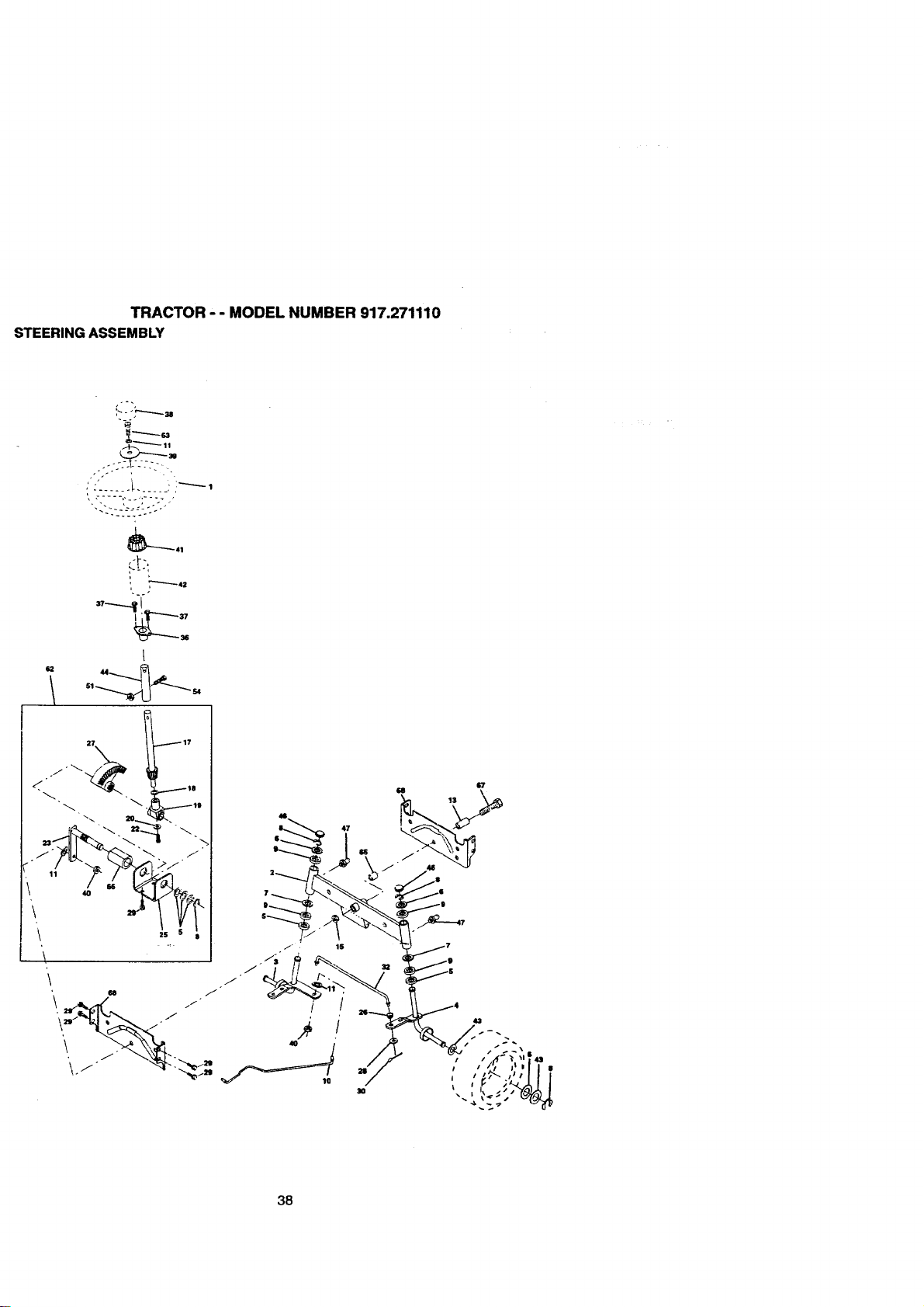
TRACTOR " " MODEL NUMBER 917.271110
STEERING ASSEMBLY
,'L':..... _...... i i¸-----,
I
_.
$2 44...__
27 17
X
/
88
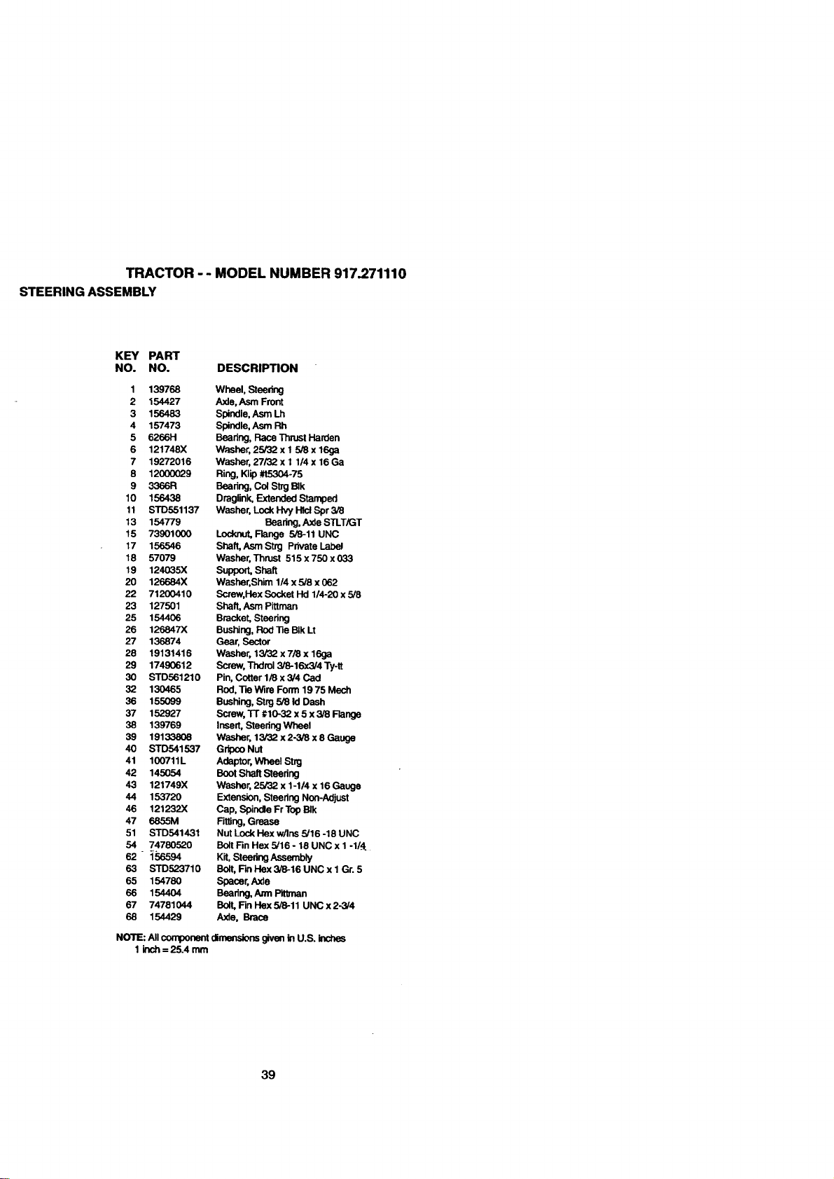
TRACTOR - - MODEL NUMBER 917.271110
STEERING ASSEMBLY
KEY PART
NO. NO. DESCRIPTION
1 139768 Wheel, Steering
2 154427 Axle, Asm Front
3 156483 Spindle, Asm Lh
4 157473 Spindle, Asm Rh
5 6266H Bearing, Race Thrust Harden
6 121748X Washer,25/32x1 5/8x16ga
7 19272016 Washer, 27/32x1 1/4x16Ga
8 12000029 Ring, Klip #t5304-75
9 3366R Bearing, Col Strg BIk
10 156438 Draglink, Extended Stamped
11 STD551137 Washer, Lock Hvy I-IlclSpr 3/8
13 154779 Bearing, Axle STLT/GT
15 73901000 Locknut, Flange 5/8-11 UNC
17 156546 Shaft, AsmStrg Private Label
18 57079 Washer, Thrust 515 x 750 x 033
19 124035X Support, Shaft
20 126884X Washer, Shim 1/4 x 5/8 x 062
22 71200410 Screw,Hex Socket Hd 1/4-20 x 5/8
23 127501 Shaft, Asm Pittman
25 154406 Bracket, Steering
26 126847X Bushing, Rod _e BIk Lt
27 136874 Gear, Sector
28 19131416 Washer, 13/32 x 7/8 x 16ga
29 17490612 Screw, Tndrol 3/8-16x3/4 Ty-tt
30 STD561210 Pin, Cotter 1/8 x 3/4 Cad
32 130465 Rod, Tte Wire Form 19 75 Mech
36 155099 Bushing, Strg 5/8 Id Dash
37 152927 Screw, "Fr #1o-32 x 5 x 3/8 Flange
38 139769 Insert, Steedng Wheel
39 19133808 Washer, 13/32 x 2-3/8 x 8 Gauge
40 STD541537 Gripco Nut
41 100711L Adaptor, Wheel Stng
42 145054 Boot Shaft Steadng
43 121749X Washer, 25/32 x 1-1/4 x 16 Gauge
44 153720 Extension, Steering Non-Adjust
46 121232X Cap, Spindle Fr Top BIk
47 6855M Fitting,Grease
51 STD541431 Nut Lock Hex w/Ins 5/16 -18 UNC
54 74780520 Bolt Fin Hex 5/16 - 18 UNC x I -1/i
62 - :1'56594 Kit, Steering Assembly
63 STD523710 Bolt, Ftn Hex 3/8-16 UNC x I Gr. 5
65 154780 Spacer, Axle
66 154404 Beadng, Ann Pit,nan
67 74781044 Bolt, FinHaxS/8-11 UNCx2-3/4
68 154429 Axle, Brace
NOTE: All component dimensions given in U.S. inches
1 inch = 25.4 mm
39
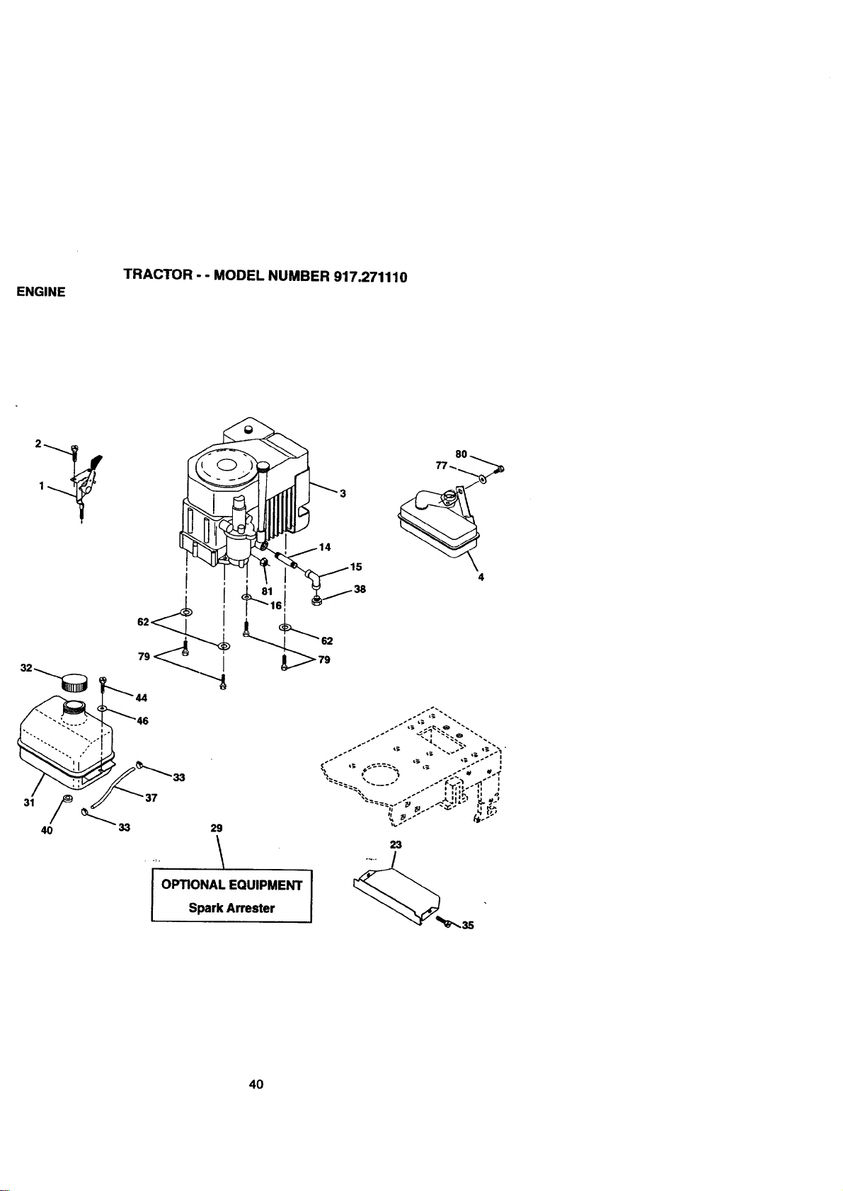
ENGINE
TRACTOR - - MODEL NUMBER 917.271110
i
3 37
40 _ 33 29
I OPTIONAL EQUIPMENT
Spark Arrester
6
8O
4
23
4O
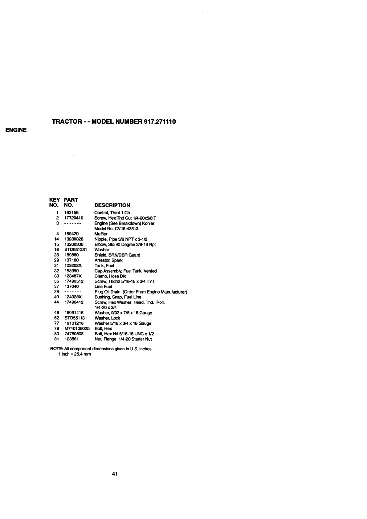
ENGINE
TRACTOR -- MODEL NUMBER 917.271110
KEY PART
NO. NO. DESCRIPTION
1 162156 Control, Throt I Ch
2 17720410 Screw, Hex Thd Cut 1/4-20x5/8 T
3 Engine (See Breakdown) Kohler
Model No. CV16-43513
4 159420 Muffler
14 13280328 Nipple, Pipe 3/8 NPT x 3-1/2
15 13200300 Elbow, Std 90 Degree 3/8-18 Npt
16 STD551231 Washer
23 159880 Shield, BRN/DBR Guard
29 137180 Arrestor, Spark
31 109202X Tank, Fuel
32 158990 Cap Assembly, Fuel Tank, Vented
33 123487X Clamp, Hose BIk
35 17490512 Screw, Thdrol 5/16-18 x 3/4 TYT
37 137040 Line Fuel
38 ....... Plug Oil Drain (Order From Engine Manufacturer)
40 124028X Bushing, Snap, Fuel Line
44 17490412 Screw, HexWasher Head, I"hd. Roll.
1/4-20 x 3/4
46 19091416 Washer, 9/32 x 7/8 x 16 Gauge
62 STD551131 Washer, Lock
77 19101216 Washer 5/16 x 3/4 x 16 Gauge
79 M740108025 Bolt, Hex
80 74760508 Bolt, Hex Hd 5/16-18 UNC x 1/2
81 128861 Nut, Flange 1/4-20 Starter Nut
NOTE: All component
1 inch = 25.4 mm
dimensions given in U.S. inches
41
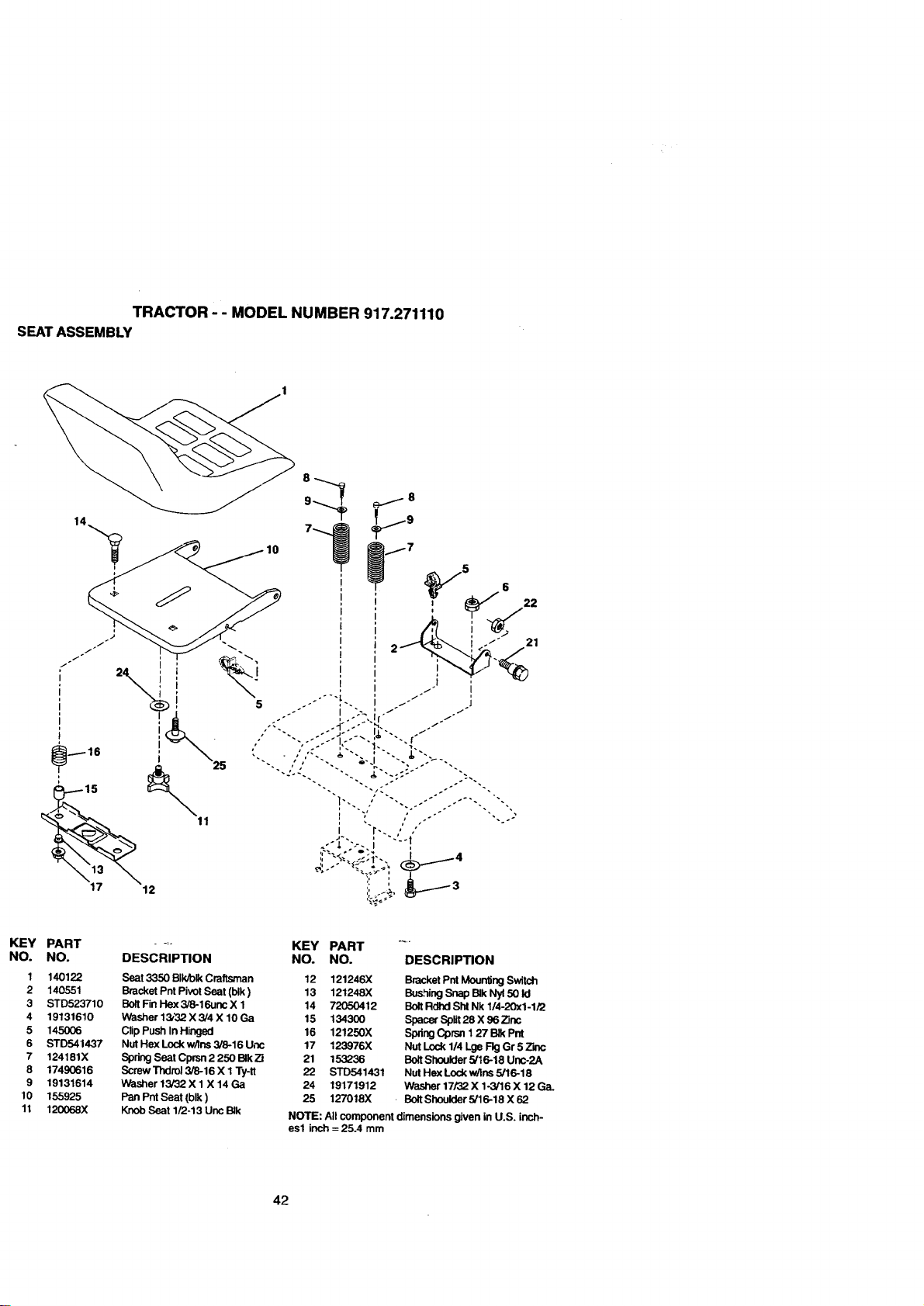
TRACTOR -- MODEL NUMBER 917.271110
SEATASSEMBLY
5
21
1
2
3
4
5
6
7
8
9
10
11
PART .... KEY PART ....
NO. DESCRIPTION NO. NO. DESCRIPTION
140122 Seat 3350 BIk/blk Craftsman 12 121246X Bracket Pnt Mounting Switch
140551 Bracket Pnt Pivot Seat (blk) 13 121248X BushingSnap BIk Ny150 Id
STD523710 Bolt Fin Hex 3/8-16unc X 1 14 72050412 Bolt Rdhd Sht Nk 1/4-20x1-1/2
19131610 Wast_er 13/32 X 3/4 X 10 Ga 15 134300 Spacer Split 28 X 96 Zinc
145006 Clip Push In Hinged 16 121250X Spring Cprsn 1 27 BIk Pnt
STD541437 Nut Hex Lock w/Ins 3/8-16 Unc 17 123976X Nut Lock 1/4 Lge Fig Gr 5 Zinc
124181X Spdng Seat Cpmn 2 250 BIkZi 21 153236 Bolt Shoulder 5/16-18 Unc-2A
17490616 Screw Thdml 3/8-16 X 1Ty-lt 22 STD541431 Nut Hex Lock w/Ins 5/16-18
19131614 Washer 13/32 X 1X 14 Ga 24 19171912 Washer 17/32 X 1-3/16 X 12 Ga.
155925 PanPntSeat(blk) 25 127018X - BoltShoulder5/16-18X62
120068X Knob Seat 1/2-13 Unc BIk NOTE: All component dimensions given in U.S. inch-
esl inch = 25.4 mm
42
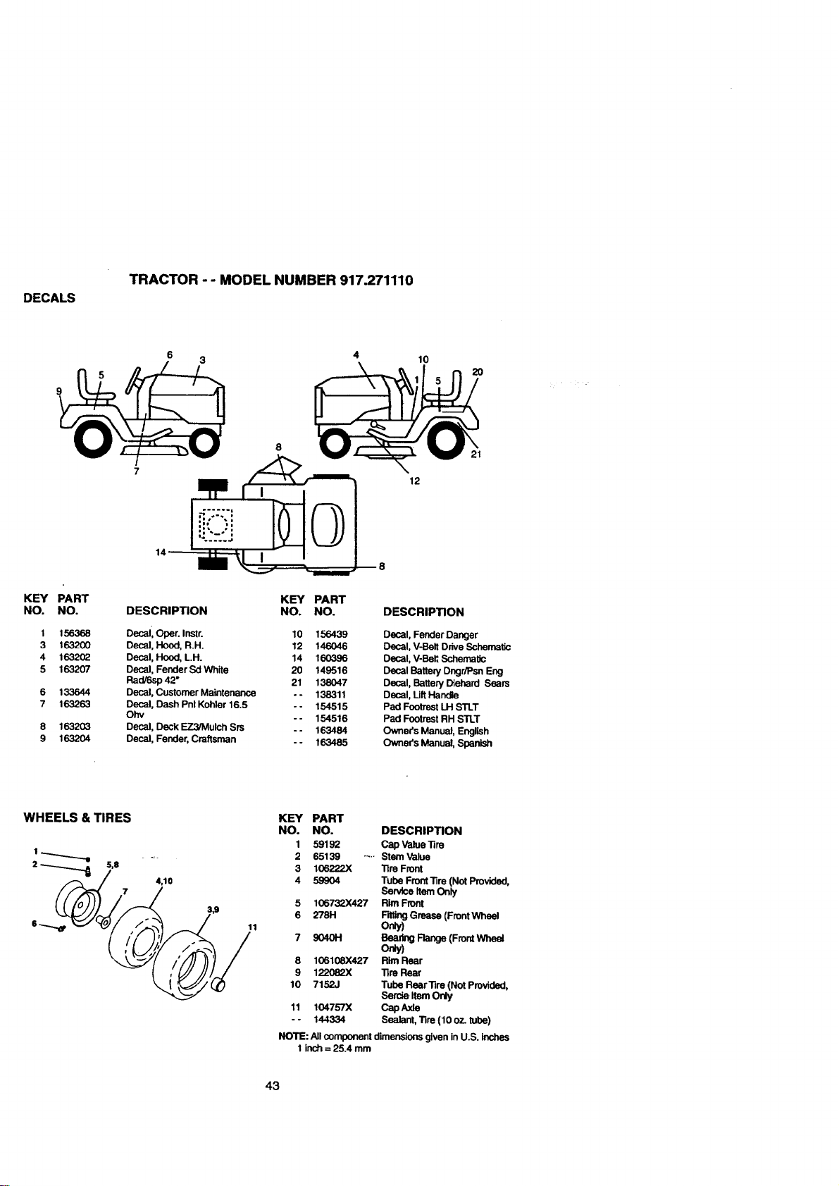
DECALS
TRACTOR - - MODEL NUMBER 917.271110
KEY
NO.
1
3
4
5
6
3
/
4 10
PART
NO. DESCRIPTION
KEY PART
NO. NO. DESCRIPTION
156368 Decal, Oper. Instr. 10 156439
163200 Decal, Hood, R.H. 12 146046
163202 Decal, Hood, L.H. 14 160396
163207 Decal, Fender Sd White 20 149516
Rad/6sp 42" 21 138047
133644 Decal, Customer Maintenance - - 138311
163263 Decal, Dash Pnl Kohler 16.5 -- 154515
Ohv
- - 154516
163203 Decal, Deck EZ3/Mulch Srs - - 163484
163204 Decal, Fender, Craftsman - - 163485
Decal, Fender Danger
Decal, V-Bell Drive Schematic
Decal, V-Beff,Schematic
Decal Battery DngdPsn Eng
Decal, Battery Diehard Sears
Decal, Lift Handle
Pad Footrest LH STLT
Pad Footrest RH STLT
Owner's Manual, English
Owner's Manual, Spanish
WHEELS & TIRES KEY PART
NO. NO.
1 59192
1"""-"_"-I .... 2 65139 ....
2 _ S,8 3 106_?.2X
4,10 4 59904
106732X427
278H
9040H
8 106108X427
9 122082X
10 7152J
11 104757X
- - 144334
DESCRIPTION
Cap Value "1ire
Stem Value
Tire Front
Tube Front Tire (Not Provided,
Service Item Only
Rim Front
F'_ng Grease (Front Wheel
o_)
Bea_.gRange(FrontWhe_
On_
Rim Rear
Tire Rear
Tube Rear Tire (Not Provided,
Sercle Item Only
Cap Axle
Sealant, Tire (10 oz. tube)
NOTE: All component dimensions given in U.S. inches
1 inch = 25.4 mm
43
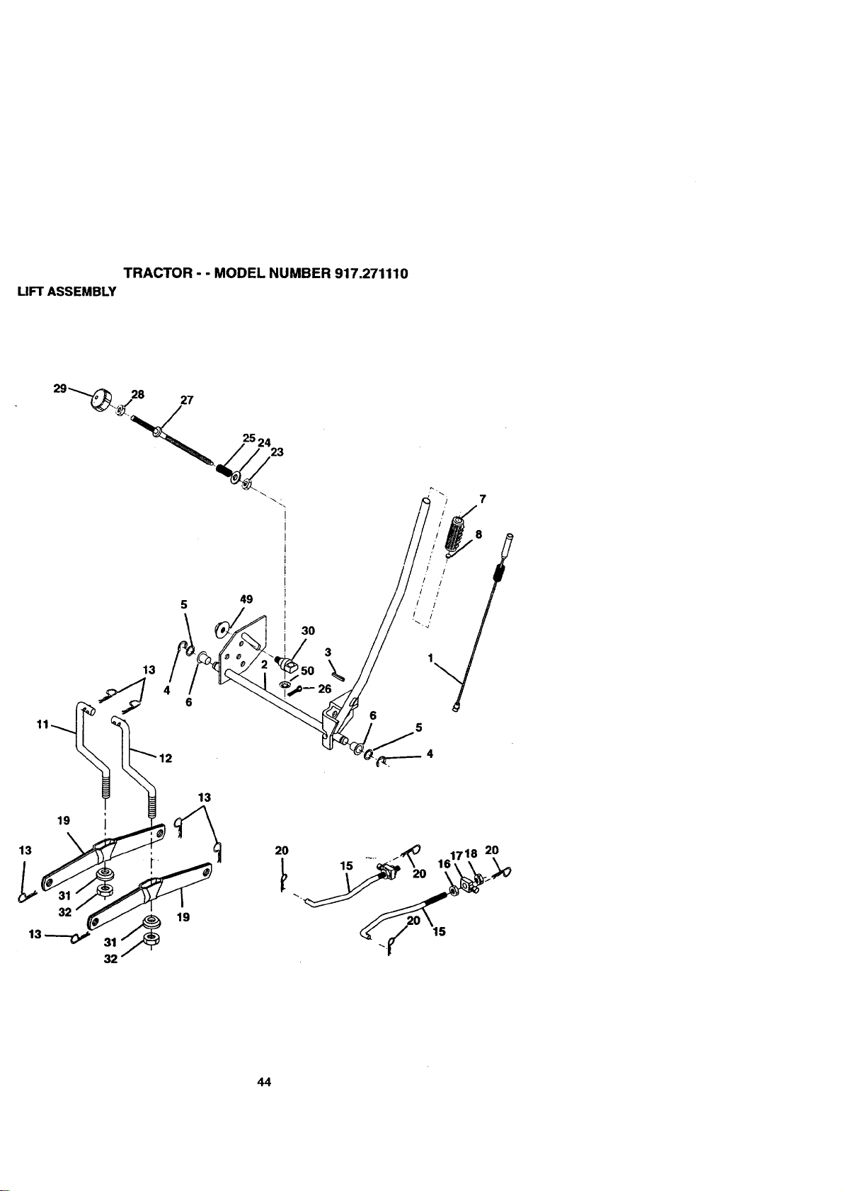
TRACTOR - - MODEL NUMBER 917.271110
LIFT ASSEMBLY
28 27
25 24
23
13
13
19
13
f
32
13
49
30
3
\
26
.I /
,/ /'
,/ 1'
/ /
5
4
20
15
44
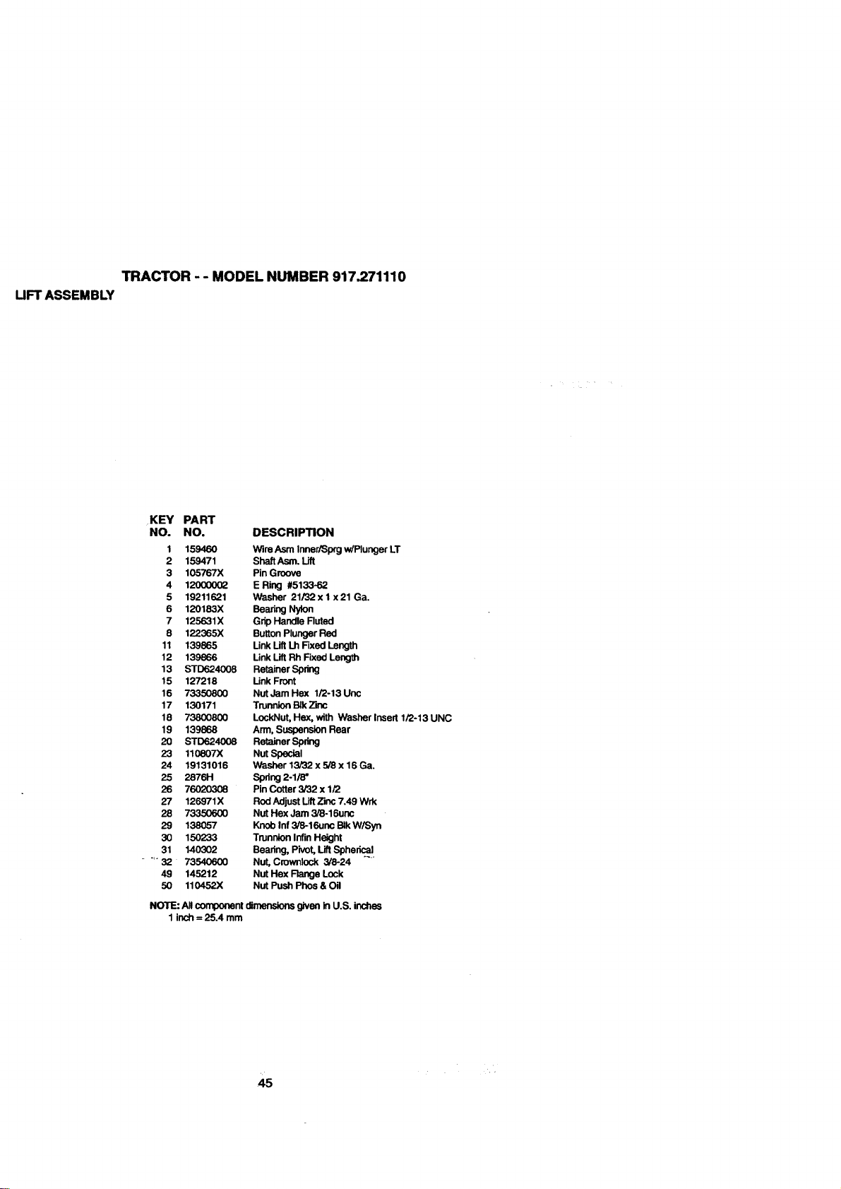
TRACTOR - - MODEL NUMBER 917.271110
UFT ASSEMBLY
KEY PART
NO. NO. DESCRIPTION
1 159460 Wire Asm Inner/Sprg w/Plunger LT
2 159471 Shaft Asm. Lift
3 105767X Pin Groove
4 120(X)062 E Ring #5133-62
5 19211621 Washer 21/32xl x21Ga.
6 120183X Bearing Nylon
7 125631X Grip Handle Ruted
8 122365X Button Plunger Red
11 139865 Unk Lift Lh Fixed Length
12 139866 Link Lift Rh Fixed Length
13 STD624008 Retainer Spdng
15 127218 Unk Front
16 73350800 Nut Jam Hex 1/2-13 Uric
17 130171 Trunnion BIk _mc
18 73800800 LockNut, Hex, with Washer Insert 1/2o13 UNC
19 139868 Arm, Suspension Rear
20 STD624008 Retainer Spring
23 110807X Nut Special
24 19131016 Washer 13/32 x 5/8 x 16 Ga.
25 2876H Spring 2-1/8"
25 76020308 Pin Cotter 3/32 x 1/2
27 126971X Rod Adjust LiftZinc 7.49 Wrk
28 73350600 Nut Hex Jam 3/8-16unc
29 138057 Knob Inf 3/8-16unc BIk W/Syn
30 150233 Trunnion Infin Height
31 140302 Bearing, Pivot, LiftSpheric.!!.
.... 32 73540600 Nut, Cmwnlock 3/8-24
49 145212 Nut Hex Range Lock
50 110452X Nut Push Phos & O=1
NOTE: A!l component dimensions given in U.S. inches
1 inch = 25.4 mm
4s
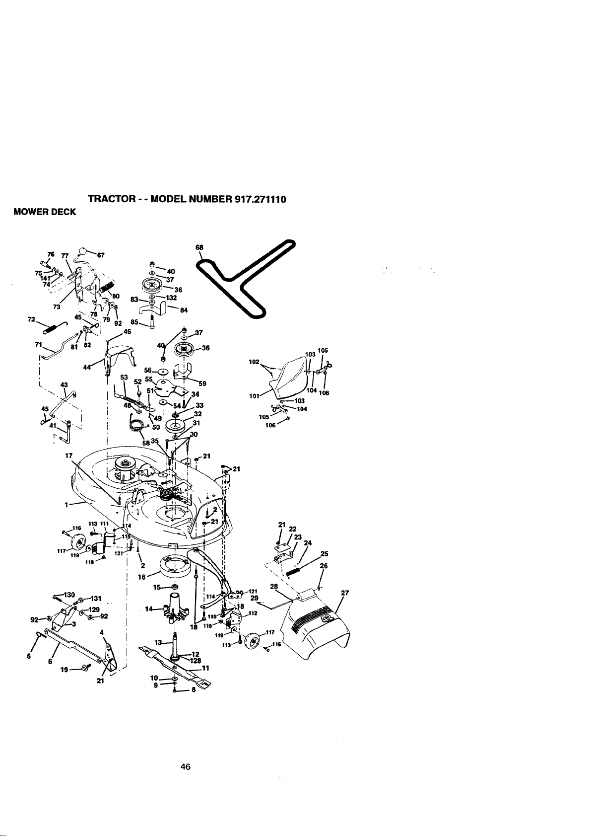
TRACTOR - - MODEL NUMBER 917.271110
MOWER DECK
58
17 ,_-21
21
22
'23
24
_2 26
16
13_ 18
_11
\
28 \
27
46
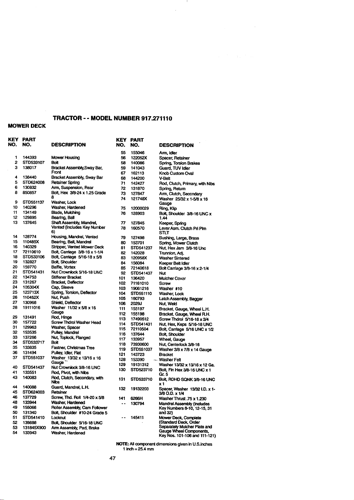
TRACTOR - - MODEL NUMBER 917.271110
MOWER DECK
KEY PART KEY PART
NO. NO. DESCRIPTION NO. NO. DESCRIPTION
1
2
3
4
5
6
8
9
10
11
12
13
14
15
16
17
18
19
2O
21
22
23
24
25
26
27
28
29
3O
31
32
33
34
35
36
37
40
41
43
44
45
46
48
49
5O
51
52
53
54
55 155046 Arm, Idler
144393 Mower Housing 56 122052X Spacer, Retainer
STD533107 Bolt 56 140086 Spring, Torsion Brakes
138017 Bracket Assembly, Sway Bar, 59 141043 Guard, TUV Idler
Front 67 162113 Knob Custom Oval
138440 Bracket Assembly, Sway Bar 68 144200 V-Belt
STD624008 Retainer Spdng 71 142427 Rod, Clutch, Pdmary, with Nibs
130832 Arm, Suspension, Rear 72 131870 Spdng, Return
850857 Bolt, Hex 3/8-24 x 1.25 Grade 73 127847 Arm, Clutch, Secondary
8 74 121748X Washer 25/32 x 1-5/8 x 16
STD551137 Washer, Lock Gauge
140296 Washer, Hardened 75 12000029 Ring, Klip
134149 Blade, Mulching 76 128903 Bolt, Shoulder 3/8-16 UNC x
129895 Bearing, Ball 1.44
137645 Shaft Assembly, Mandrel, 77 127845 Keeper, Spdng
Vented (Includes Key Number 78 160570 LeverAsm. Clutch Pd PIm
6) STLT
128774 Housing, Mandrel, Vented 79 127498 Bushing, Large, Brass
110485X Beadng, Ball, Mandrel 80 153"101 Spdng, Mower Clutch
140329 Stripper, Vented Mower Deck 81 STD541237 Nut, Hex Jam 3/8-16 Une
72110610 Bolt, Cardage 3/8-16 x 1-1/4 82 142028 Trunnion, Adj.
STD533106 Bolt, Carriage 5/16-18 x 5/8 83 12O958X Washer Sintered
132827 Bolt, Shoulder 84 156084 Keeper Belt Idler
159770 Baffle, Vortex 85 72140618 Bolt Carriage 3/8-16 x 2-1/4
STD541431 Nut Crownlock 5/16-18 UNC 92 STD541437 Nut
134753 Stiffener Bracket 101 136420 Mulcher Cover
131267 Bracket, Deflector 102 71161010 Screw
105304X Cap, Sleeve 103 19061216 Washer #10
123713X Spring, Torsion, Deflector 104 STD551110 Washer, Lock
110452X Nut, Push 105 160793 Latch Assembly, Bagger
130968 Shield, Deflector 106 2029J Nut, Weld
19111016 Washer 11/32 x 5/8 x 16 111 155197 Bracket, Gauge, Whee_ LH.
Gauge 112 155198 Bracket, Gauge, Wheel R.H.
131491 Rod, Hinge 113 17490512 ScrewThdro_ 5/16-18x3/4
157722 Screw Thdrol Washer Head 114 STD541431 Nut, Hax, Keps 5/16-18UNC
129963 Washer, Spacer 115 72110504 Bolt, Carriage 5/16UNCx1/2
153535 Pulley, Mandrel 116 137644 Bolt, Shoulder
137266 Nut, Toplock, Ranged 117 133957 Wheel, Gauge
STD533717 Bolt 118 73930600 Nut, Centedock 3/8-16
133835 Fastner, Christmas Tree 119 STD551037 Washer 3/8 x 7/8 x 14 Gauge
131494 Pulley, Idler, Flat 121 143723 Bracket
STD551037 Washer 13/32 x 13/16 x 16 128 153390 ---Washer Felt
Gauge 4. 129 19131312 Washer 13/32 x 13/16 x 12 Ga.
STD541437 Nut Crownlock 3/8-16 UNC 130 STD523710 Bolt, Fin Hex 3/8-16 UNC x 1
133551 Rod, Pivot, with Nibs Gr. 5
140083 Rod, Clutch, Secondary, with 131 STD533710 Bo_t,RDHD SQNK 3/8-16 UNC
Nibs x 1
140088 Guard, Mandrel, LH. 132 19132203 Spacer, Washer 13/321.D. x1-
STD624003 Retainer 3/80.D. x 114
137729 Screw, Thd. Roll 1/4-20x5/8 141 3255H WasherThrust.75x1.233
133944 Washer, Hardened - - 130794 MandrelAssembly (Includes
155066 Roller Assembly, Cam Follower Key Numbers 8-10,12-15, 31
131340 Bolt, Shoulder #10-24 Grade 5 and 32)
STD541410 Locknut - - 145411 Mower Deck, Complete
139888 Bolt, Shoulder 5/16-18 UNC (Standard Deck, Order
131845X900 Arm Assembly, Pad, Brake Separately Mulcher Plate and
133943 Washer, Hardened Gauge Wheel Components,
Key Nos. 101-106 and 111-121)
NOTE: All component dimensions given in U.S.inchas
1 inch = 25.4 mm
47
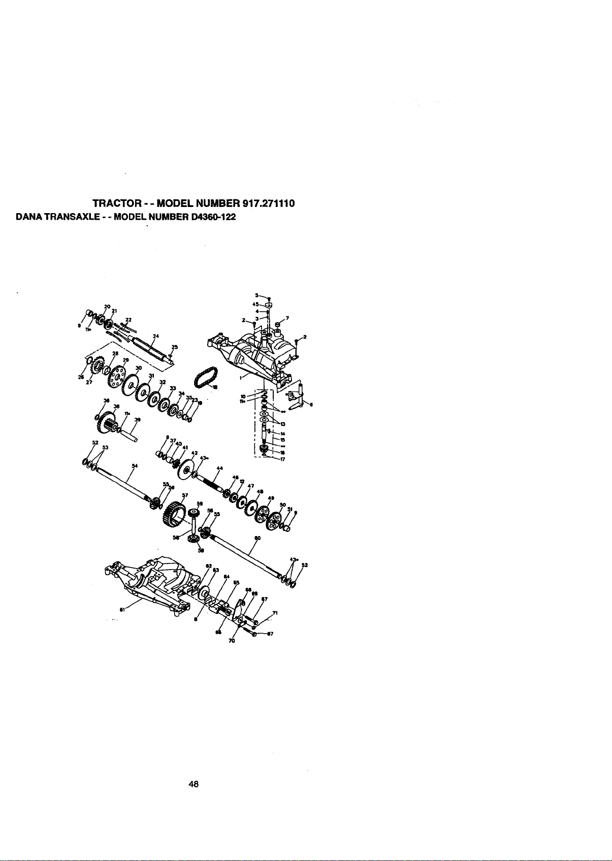
TRACTOR - - MODEL NUMBER 917.271110
DANA TRANSAXLE - - MODELNUMBER D4360-122
2O
21
22
24
47
48
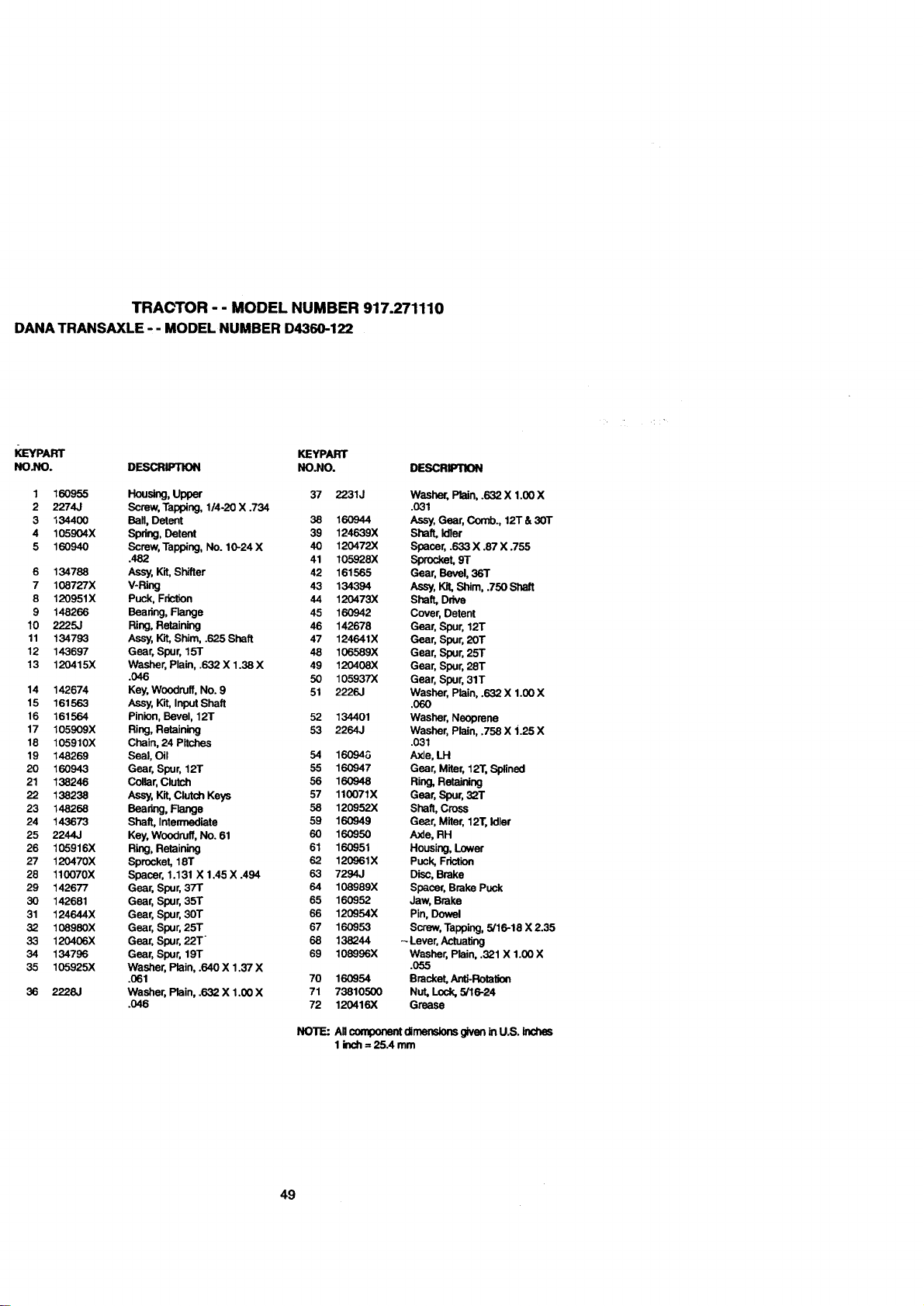
TRACTOR - - MODEL NUMBER 917.271110
DANA TRANSAXLE-- MODEL NUMBER D4360-122
KEYPART KEYPART
NO.NO. DESCRIPTION NO.NO.
1 160955 Housing, Upper 37 2231J
2 2274J Screw, Tapping, 1/4-20 X .734
3 134400 Ball, Detent 38 160944
4 105904X Spdr_, Detent 39 124639X
5 160940 Screw, Tapping, No. 10-24 X 40 120472X
.482 41 105928X
6 134788 Assy, Kit, Shifter 42 161565
7 108727X V-Ring 43 134394
8 120951X Puck, Friction 44 120473X
9 148266 Bearing, Flange 45 160942
10 2225J Ring, Retaining 46 142678
11 134793 Assy, Kit, Shim, .625 Shaft 47 124641X
12 143697 Gear, Spur, 15T 48 106589X
13 120415X Washer, Plain, .632 X 1.38 X 49 120408X
.046 50 105937X
14 142674 Key, Woodruff, No. 9 51 2226J
15 161563 Assy, Kit, Input Shaft
16 161564 Pinion, Bevel, 12T 52 134401
17 105909X Ring, Retaining 53 2264J
18 105910X Chain, 24 Pitches
19 148269 Seal, Oil 54 16G94G
20 160943 Gear, Spur, 12T 55 160947
21 138248 Collar, Clutch 56 160948
22 138238 Assy, Kit, Clutch Keys 57 110071X
23 148255 Bearing, Flange 58 120952X
24 143673 Shaft, Intermediate 59 160949
25 2244J Key, Woodruff, No. 61 60 160950
26 105916X Ring, Retaining 61 160951
27 120470X Sprocket, 18T 62 120961X
28 110070X Spacer, 1.131 X 1.45 X .494 63 7294J
29 142677 Gear, Spur, 37T 64 108989X
30 142681 Gear, Spur, 35T 65 160952
31 124644X Gear, Spur, 30T 66 120954X
32 108980X Gear, Spur, 25T 67 160953
33 120406X Gear, Spur, 22T 68 138244
34 134796 Gear, Spur, 19T 69 108996X
35 105925X Washer, Plain, .640 X 1.37 X
.061 70 160954
38 2228J Washer, Plain, .632 X 1.00 X 71 73810500
.046 72 120416X
DESCRIPTION
Washer, Plain, .632 X 1.00 X
.031
Assy, Gear, Comb., 12T & 30T
Shaft, Idler
Spacer, .633 X .87 X .755
Sprocket,ST
Gear, Bevel, 36T
Assy, Kit, Shim, .750 Shaft
Shaft, Drive
Cover, Detent
Gear, Spur, 12T
Gear, Spur, 20T
Gear, Spur, 25T
Gear, Spur, 28T
Gear, Spur, 31T
Washer, Plain, .632 X 1.00 X
.060
Washer, Neoprene
Washer, Plain, .758 X i.25 X
.031
Axle, LH
Gear, Miter, 12"1",Splined
Ring, Retaining
Gear, Spur, 32T
Shaft, Cross
Gear, Miter, 12T, Idler
Axle, RH
Housing, Lower
Puck, Friction
Disc, Brake
Spacer, Brake Puck
Jaw, Brake
Pin, Dowel
Screw, Tapping, 5/16-18 X 2.35
-_Lever, Actuating
Washer, Plain, .321 X 1.00 X
.055
Bracket, Anti-Rotation
Nut, Lock, 5/16-24
Grease
NOTE: AllcomponentdimensionsgivenInU.S. Inches
1Inch= 25A mm
49
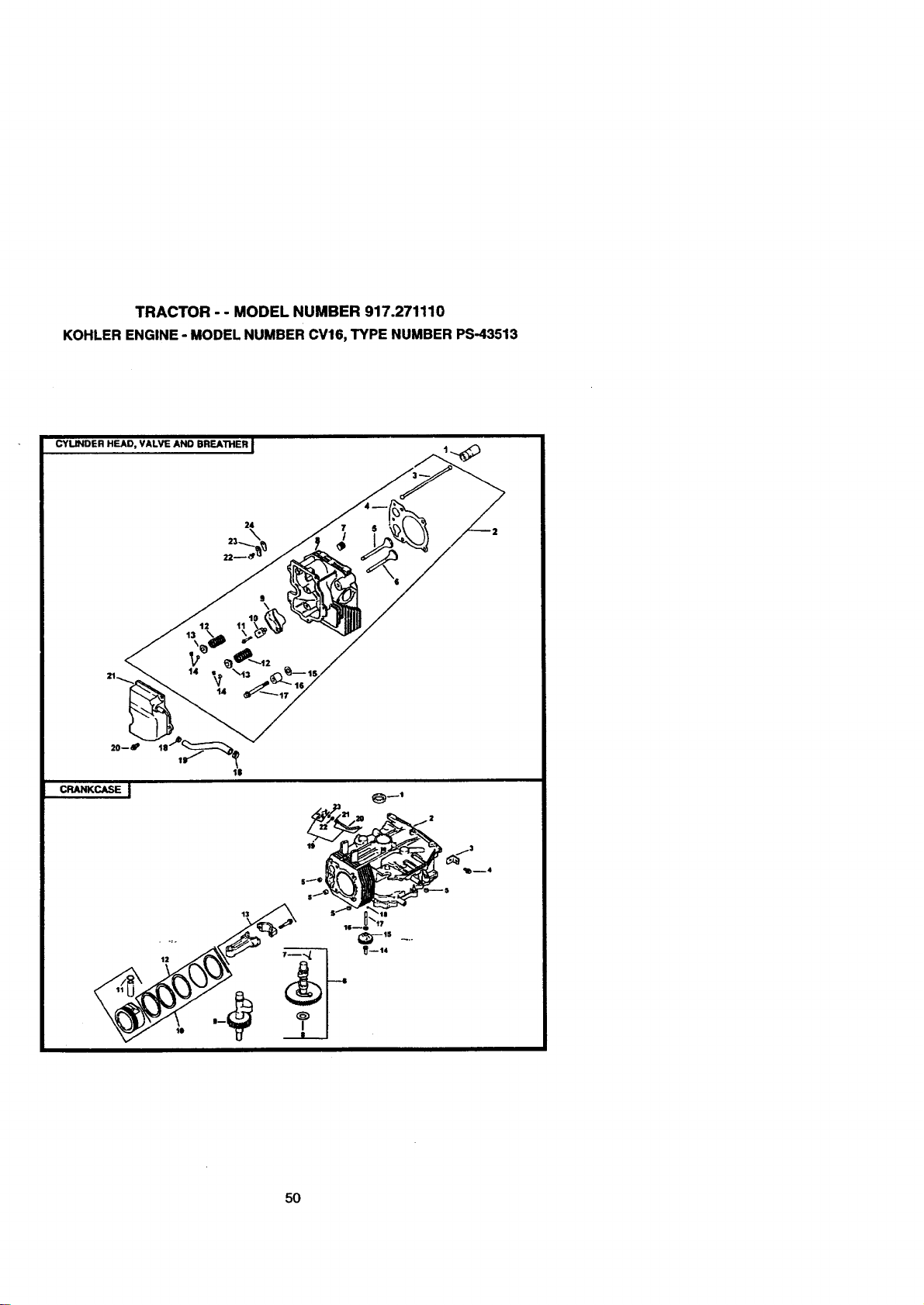
TRACTOR - - MODEL NUMBER 917.271110
KOHLER ENGINE- MODEL NUMBERCV16, TYPE NUMBER PS-43513
CYLINDER HEAD, VALVE AND BREATHER J
2_ /-2
20--0
CRANKCASE ]
15
5O
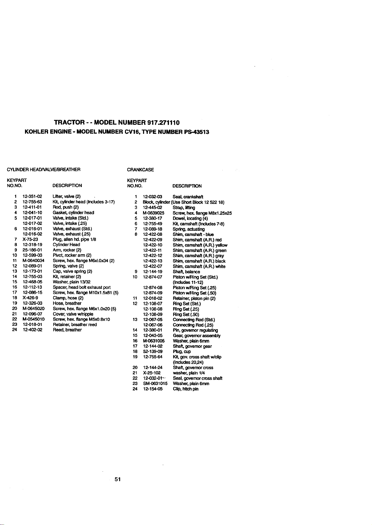
TRACTOR - - MODEL NUMBER 917.271110
KOHLER ENGINE- MODEL NUMBER CV16, TYPE NUMBER PS-43513
CYLINDER HEADNALVE/BREATHER
KEYPART
NO.NO.
CRANKCASE
1
2
3
4
5
6
7
8
9
10
11
12
13
14
15
16
17
18
19
2O
21
22
23
24
12-351-02
12-755-63
12-411-01
12-041-10
12-017-01
12-017-02
12-016-01
12-016-02
X-75-23
12-318-19
25-186-01
12-599--03
M-0640034
12-089-01
12-173-01
12-755-03
12-468-05
12-112-13
12-086-15
X-425-9
12-326-03
M-0645020
12-096-07
M-0545010
12-018-01
12-402-02
KEYPART
DESCRIPTION NO.NO. DESCRIPTION
Lifter, valve (2) 1
Kit, cylinder head (Includes 3-17) 2
Rod, push (2) 3 12-445-02
Gasket, cylinder head 4 M-0839025
Valve, intake (Std.) 5 12-380-17
Valve, intake (25) 6 12-755-49
Valve, exhaust (Std.) 7 12-089-18
Valve, exhaust (25) 8 12-422-08
Plug, allen hd. pipe 1/8 12-422-O9
Cylinder Head 12-422-10
Arm, rocker (2) 12-422-11
Pivot, rocker arm (2) 12-422-12
Screw, hex. flange M6xl.0x34 (2) 12-422-13
Spring, valve (2) 12-422-07
Cap, valve spring (2) 9 12-144-19
Kit, retainer (2) 10 12-874-07
Washer, plain 13/32
Spacer, head bolt exhaust port 12-874-08
Screw, hex. flange M10x1.5x81 (5) 12-874-09
Clamp, bose (2) 11 12-018-02
Hose, breather 12 12-108-07
Screw, hex. flange M6xl.0x20 (5) 12-108-08
Cover, valve w/nipple 12-108-09
Screw, hex. flange M5xO.8xl0 13 12-067-05
Retainer, breather reed 12-067-06
Reed, breather 14 12-380-01
15 12-O43-05
16 M-0631005
17 12-144-02
18 52-139-09
19 12-755-64
20 12-144-24
21 X-25-102
22 12-032-01-'"
23 SM-0631015
24 12-154-05
12-032-03 Seal, crankshaft
Block, cylinder (Use Short Block 12 522 18)
Strap, lifting
Screw, hex. flange M8x1.25x25
Dowel, locating (4)
_t, camshaft (tncludes 7-8)
Spr_j,actuaUng
Shim, camshaft-blue
Shim,camshaft(A.R.)red
Shim, camshaft (A.R.) yeBow
Shim, camshaft (A.R.) green
Shim, camshaft (A.R.) gray
Shim, camshaft (A.R.) black
Shim, camshaft (A.R.) white
Shaft, balance
Piston w/Ring Set (Std.)
(Includes 11-12)
Piston w/Ring Set {25)
Piston w/Ring Set (.50)
Retainer, p_on pin (2)
RingSet(S_.)
Ring Set (25)
Ring Set (.50)
Connec_gRod(SU.)
Connecting Red (25)
Pin, governor regulating
Gear, governor assembly
Washer, plain 6ram
Shaft, governor gear
Plug, cup
Kit, gov. cross shaft w/clip
(Indudes 20,24)
Shaft, govamor cross
washer, plain 1/4
Seal, governor cross shaft
Washer. plain 6ram
Clip, hitch pin
51
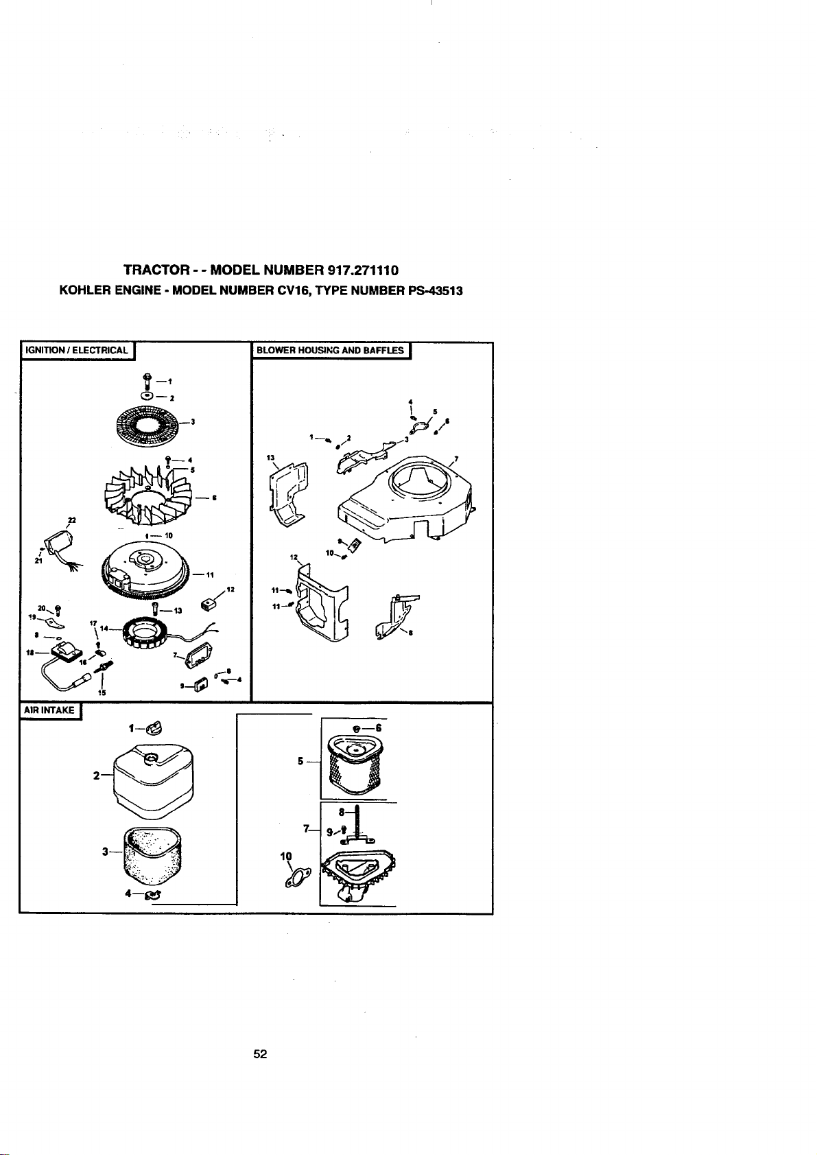
TRACTOR - - MODEL NUMBER 917.271110
KOHLER ENGINE- MODEL NUMBER CV16, TYPE NUMBERPS-43513
IGNITION / ELECTRICAL I
_ I-- 10
12
20_._
AIR INTAKE I
1-8
4--1;_r
BLOWER HOUSING AND BAFFLES I
4
5
_, $
13 1--_, m/_13
11
52
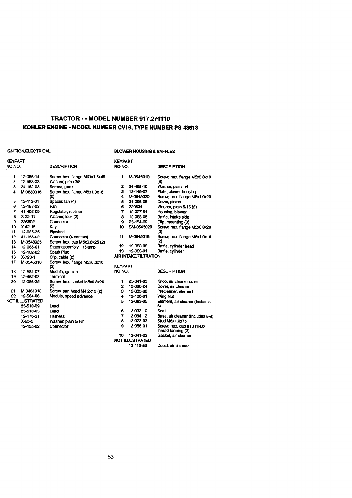
TRACTOR - - MODEL NUMBER 917.271110
KOHLER ENGINE - MODELNUMBER CV16, TYPE NUMBER PS-43513
IGNITION/ELECTRICAL
KEYPART
NO.NO. DESCRIPTION
1 12-086-14
2 12-468-03
3 24-162-03
4 M-0639016
5 12-112-01
6 12-157-03
7 41-403-09
8 X-22-11
9 236602
10 X-42-15
11 12-025-35
12 41-155-02
13 M-0548025
14 12-085-01
15 12-132-02
16 X-728-1
17 M-0545010
18 12-584-07
19 12-452-02
20 12-086-35
21 M-0461013
22 12-584-06
NOT ILLUSTRATED
25-518-29
25-518-05
12-176-31
X-25-5
12-155-02
Screw, hex. flange MIOx1.Sx46
Washer, plain 3/8
Screen, grass
Screw, hex. flange M6x1.0x16
(6)
Spacer, fan (4)
Fan
Regulator, rectifier
Washer, lock (2)
Connector
Key
Flywheel
Connector (4 contact)
Screw, hex. cap M5x0.8x25 (2)
Stetor assembly- 15 amp
Spark Plug
Clip, cable (2)
Screw, hex. flange M5x0.8xl0
(2)
Module, ignition
Terminal
Screw, hex. socket M5xO.8x20
(2)
Screw, pan head M4.2x13 (2)
Module, speed advance
Lead
Lead
Harness
Washer, plain 5/16"
Connector
BLOWER HOUSING & BAFFLES
KEYPART
NO.NO. DESCRIPTION
1 M-0545010 Screw, he:<.flange M5x0.8xl0
(8)
2 24-468-10 Washer, plain 1/4
3 12-146-07 Plate, blower housing
4 M-0645020 Screw, hex. flange M6x1.0(20
5 24-096-05 Cover, pinion
6 220534 Washer, plain 5/16 (2)
7 12-027o54 Housing, blower
8 12-06305 Baffle, intake side
9 25-154-02 Clip, mounting (3)
10 SM-0545020 Screw, hex. flange M5x0.8(20
(3)
11 M-0645016 Screw, hex. flange M6x1.0x16
(2)
12 12-063-O8 Baffle, cylinder head
13 12-063-01 Baffle, cylinder
AIR INTAKE/FILTRATION
KEYPART
NO.NO. DESCRIPTION
1 25-341-03 Knob, air cleaner cover
2 12-096-24 Cover, air cleaner
3 12-083-08 Precleaner, element
4 12-100-01 Wing Nut
5 12-083-05 Element, air cleaner (Includes
8)
6 12-032-10 Seal
7 12-094-12 Base, air cleaner (Includes 8-9)
8 12-072-03 Stud M6x1.0x75
9 12-086-01 Screw, hex. cap #10 Hi-Lo
thread forming (2)
10 12-041-02 Gasket, aircleaner
NOT ILLUSTRATED
12-113-53 Decal, air cleaner
53
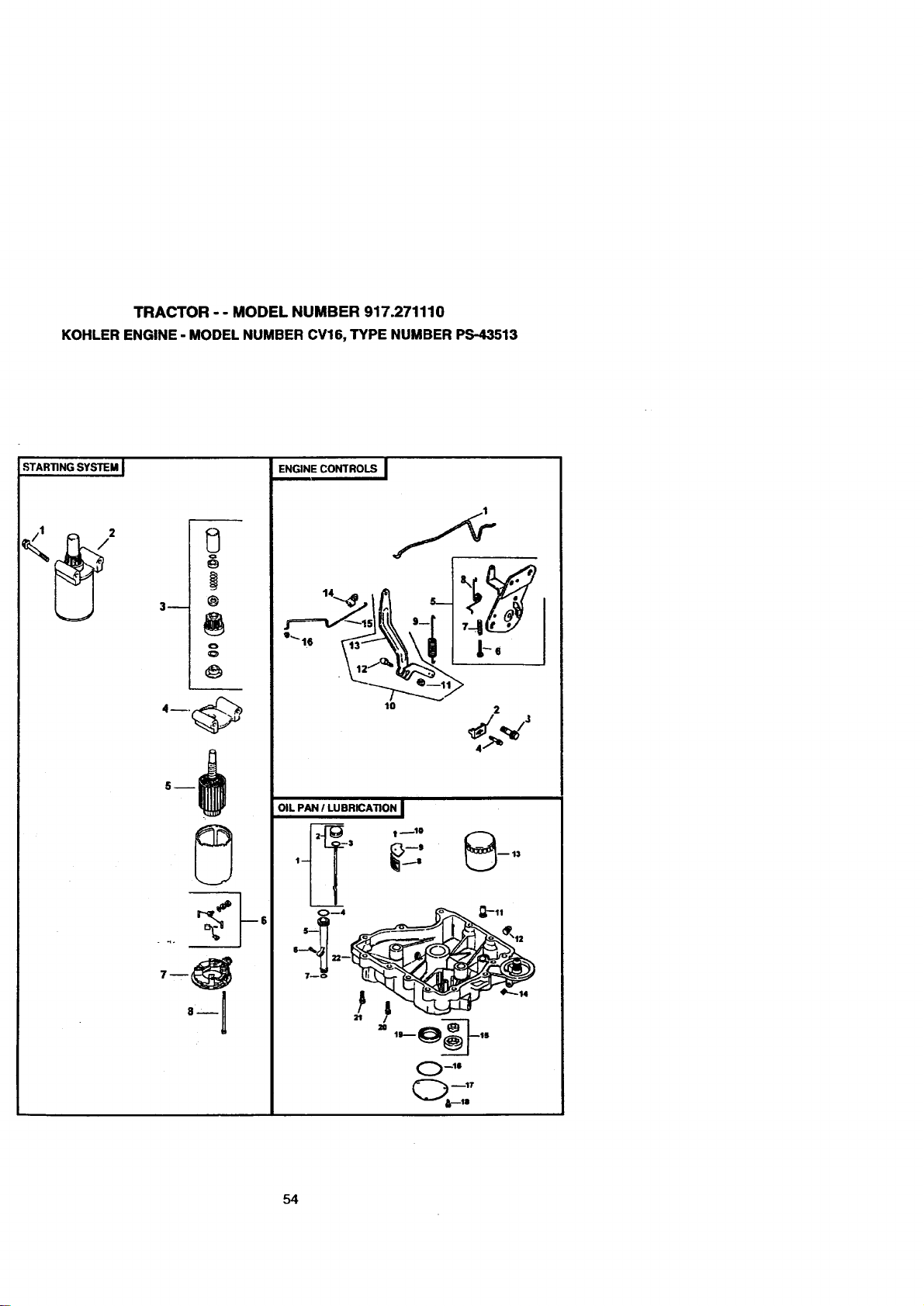
TRACTOR - - MODEL NUMBER 917.271110
KOHLER ENGINE - MODELNUMBER CV16, TYPE NUMBER PS-43513
STARTING SYSTEM J
3_
@
o
o
ENGINE CONTROLS I
to 2
OIL PAN I LUBRICATION I
,_ _-: ,,
O mt$
54
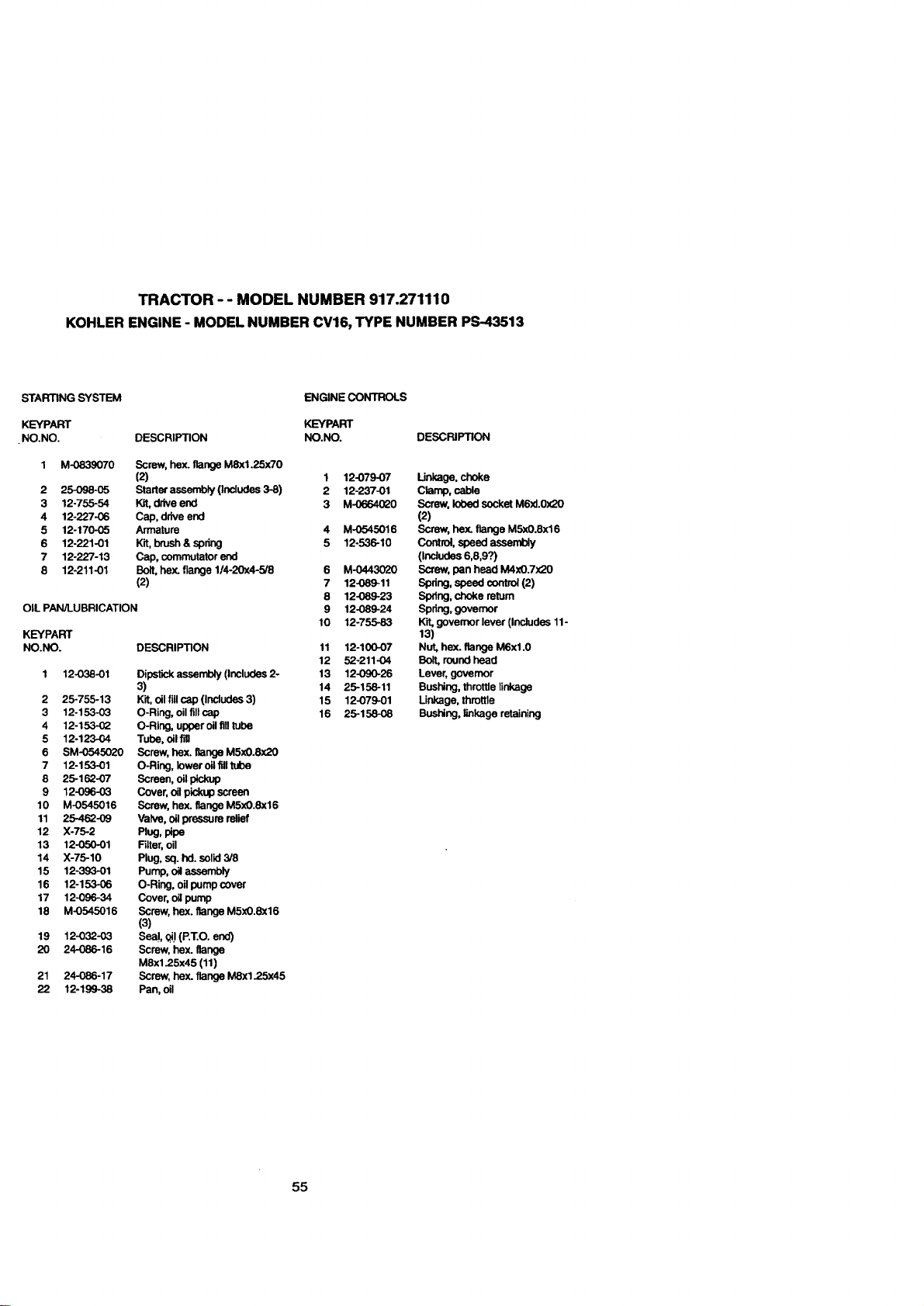
TRACTOR - - MODEL NUMBER 917.271110
KOHLER ENGINE- MODELNUMBER CV16, TYPE NUMBER PS-43513
STARTING SYSTEM
KEYPART
NO. NO.
ENGINE CONTROLS
KEYPART
DESCRIPTION NO.NO. DESCRIPTION
2
3
4
5
6
7
8
M-0839070
25-O98-O5
12-755-54
12-227 -06
12-170-05
12-221-01
12-227-13
12-211-01
Screw, hex. flange M8x1.25x70
(2)
Starter assembly (Includes 3-8)
Kit, drive end
Cap, drive end
Armature
Kit,brush&spr_j
Cap, commutator end
Bolt, hex. flange 1/4-20x4-5/8
(2)
OIL PAN/LUBRICATION
DESCRIPTION
2
3
4
5
6
7
8
9
10
11
12
13
14
15
16
17
18
19
2O
21
22
12-038-01
25-755-13
12-153-03
12-153-02
12-123-04
SM-0545020
12-153-01
25-162-07
12-096-03
M-0545016
25-462-09
X-75-2
12-050-01
X-75-10
12-393-01
12-153-06
12-096-34
M-0545016
12-032-03
24-086-16
24-086-17
12-199-38
Dipstick assembly (Includes 2-
3)
Kit, oil fill cap (Includes 3)
O-Ring, oil fillcap
O-Ring, upper oil fill tube
Tube, oil fill
Screw, hex. flange M5x0.8x20
O-Ring, lower oil fill tube
Screen, oil pickup
Cover, oil pickup screen
Screw, hex. flange M5x0.8x16
Valve, oil pressure relief
Plug, pipe
Filter, oil
Plug, sq. hal.solid 3/8
Pump, oil assembly
O-Ring, oilpump cover
Cover, oil pump
Screw, hex. flange M5x0.Sx16
(3)
Seal,_'1(P.T.O.end)
Screw, hex. flange
MSx1.25x45 (11)
Screw, hex. flange M8x1.25x45
Pan, oil
1 12-079-07
2 12-237-01
3 M-0664620
4 M-0545016
5 12-536-10
6 M-0443020
7 12-089-11
8 12-089-23
9 12-089-24
10 12-755-83
11 12-100-07
12 52-211-04
13 12-090-26
14 25-158-11
15 12079-01
16 25-158-08
Unkage, choke
Clamp, cable
Screw. lobed socket M6xl.0x20
(2)
Screw, hex. flange M5xO.8x16
Control, speed assembly
(includes 6,8,9?)
Screw, pan head M4xO.7x20
Spdng, speed control (2)
Spring, choke return
Spring, govemor
Kit, governor lever (Includes 11-
13)
Nut, hex. flange M6xl.0
Bolt, round head
Lever, governor
Bushing, throttle linkage
Linkage, throttle
Bushing, linkage retaining
55
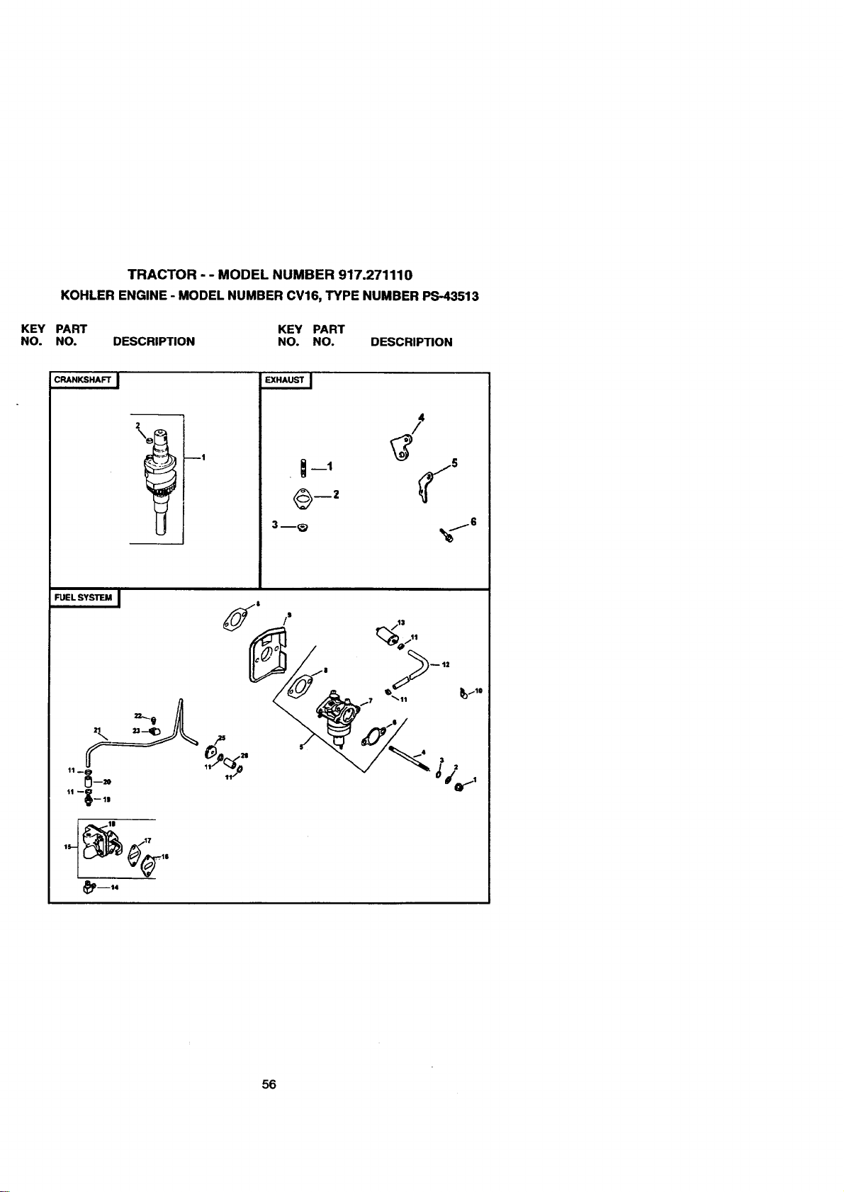
KEY
NO.
TRACTOR - - MODEL NUMBER 917.271110
KOHLER ENGINE - MODELNUMBER CV16, TYPE NUMBER PS-43513
PART KEY PART
NO. DESCRIPTION NO. NO. DESCRIPTION
C_N_HA_ J
2
--1
EXHAUST I
--1
3m_
FUEL SYSTIEM I _1 /" ,,/13
m14
56
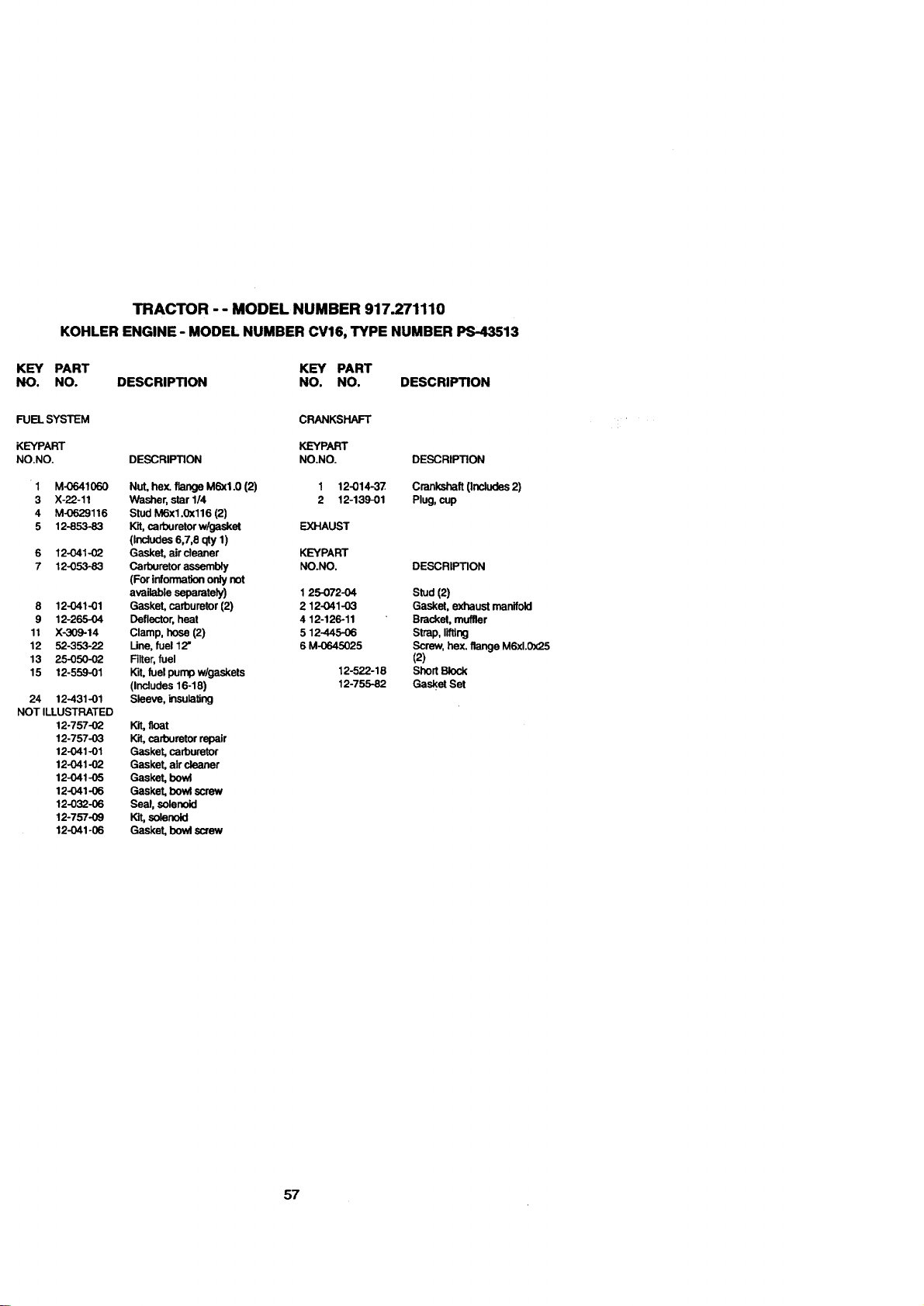
TRACTOR - - MODEL NUMBER 917.271110
KOHLER ENGINE - MODEL NUMBER CV16, TYPE NUMBER PS-43513
KEY PART
NO. NO.
KEY PART
DESCRIPTION NO. NO. DESCRIPTION
FUEL SYSTEM
KEYPART
NO.NO.
1 M-0641060
3 X-22-11
4 M-0629116
5 12-853-83
6 12-041-02
7 12-053-83
8 12-041-01
9 12-265-04
11 X-309-14
12 52-353-22
13 25-050-02
15 12-559-01
24 12-431-01
NOT ILLUSTRATED
12-757-02
12-757-03
12-041-O1
12-041-02
12-041-05
12`041-06
12-032-06
12-757-09
12-041-06
CRANKSHAFT
KEYPART
DESCRIPTION NO.NO.
Nut, hex. flange M6xl.0 (2) 1 12-014-37
Washer, star 1/4 2 12-139-01
Stud M6x1.0x116 (2)
Kit, carburetor w/gasket EXHAUST
(Includes 6,7,8 qty 1)
Gasket, air cleaner KEYPART
Carburetor assembly NO.NO.
(For information only not
available separately) 1 25-072-04
Gasket, carburetor (2) 2 12-041-03
Deflector, heat 4 12-126-11
Clamp, hose (2) 5 12-445-06
Une, fuel 12" 6 M-0645025
Filter, fuel
Kit, fuel pump w/gaskets 12-522-18
(Includes 16-18) 12-755-82
Sleeve, insulating
float
Kit, carburetor repair
Gasket, carburetor
Gasket, air cleaner
Gasket, bowl
Gasket, bowl screw
Seal, solenoid
Kit, solenoid
Gasket, bowl screw
DESCRIPTION
Crankshaft (Includes 2)
Plug, cup
DESCRIPTION
Stud (2)
Gasket, exhaust manifold
Bracket, muffler
Strap, tiffing
Screw, hex. flange M6xl.0x25
(2)
Short Block
Gasket Set
57

58

SUGGESTED GUIDE FOR SIGHTING SLOPES FOR SAFE OPERATION
ONLY RIDE UP AND DOWN HILL,
NOT ACROSS HILL
O1
t.O
SIGHT AND HOLD THIS LEVEL WITH
SKY LINE OR TREE.
15° MAX.
1
Operate your Tractor up and down the face of slopes (not
greater than 15 ), never across the face. Make turns gredu-
ally to prevent tipping or loss of control. Exercise extreme
caution when changing direction on slopes.
Fortherepairor replacementpartsyouneed
delivereddirectlytoyourhome
Call7 am - 7 pm,7 daysa week
1-800-366-PART
(1-800-366-7278)
Para ordenar piezascon entregaa
domicilio- 1-800-659-7084
Forin--housemajorbrandrepairservice
Call24 hoursa day,7 daysa week
1-800-4-REPAIR
(1-800-473-7274)
Para pedir servicio de reparaci6n a
domicilio - 1-800-676-5811
Forthelocationofa SearsPartsand
RepairCenterinyourarea
Call24 hoursa day,7 daysa week
1-800-488-1222
Forinformationon purchasinga Sears
MaintenanceAgreementortoinquire
aboutan existingAgreement
Call9 am- 5 pm,Monday-Saturday
1-800-827-6655
Whenrequestingserviceor ordering
parts,alwaysprovidethefollowing
information:
• ProductType • PartNumber
• ModelNumber • PartDescription
it
illllill II l
Illlll
SEARS
163484 12.12.97 RH
6O
America's Repair Specialrsts
Printed in U.S.A.