Loading ...
Loading ...
Loading ...
13
For household propane or natural gas units:
THE ATTACHED FLEX LINE AND REGULATOR MUST
BE PROPERLY ATTACHED TO A RIGID GAS SUPPLY
PIPE . See fi g. 13-3.
CAUTION: Use only C.S.A. listed stainless-steel fl ex
connectors within the enclosure.
WARNING
A rubber or plastic connector will rupture or leak,
resulting in an explosion or serious injury if used
inside the appliance enclosure.
1. Route the attached fl ex connector with regulator
(located underneath the grill) to the gas-supply
stub. (An adapter is required if the gas-supply stub
is other than
1
/
2
" in diameter.)
2. Turn OFF the gas supply at the source. Then
connect the regulator to the gas-supply stub. Use
pipe joint compound that is resistant to all gasses
on the male pipe fi tting and tighten securely. DO
NOT use pipe joint compound to connect fl are
fi ttings.
Note: The regulator may need to be disconnected
from the fl ex connector to make the proper
connections. Reconnect the fl ex to the
regulator if removed.
3. Turn all burner control knobs to the OFF position.
Turn the gas supply on. Then carefully check all gas
connections for leaks with a brush and half-soap/
half-water solution before lighting. Never use a
match or open fl ame to test for leaks.
4. Close the dedicated gas-supply shut-off valve, then
slide the grill into place. Do not to pinch, kink, or
damage the gas connector line.
COUNTER PREPARATION
Consult Table 1 for non-combustible enclosure cut-out
dimensions. An AOG insulating liner must be used if
any supporting construction is combustible. Consult the
instructions that come with the liner for dimensions and
additional installation information before beginning the
installation.
This outdoor built-in grill must be supported by the
stainless-steel hanger extending from the upper portion
of the grill. The hanger rests on the left, right, and back
of the countertop.
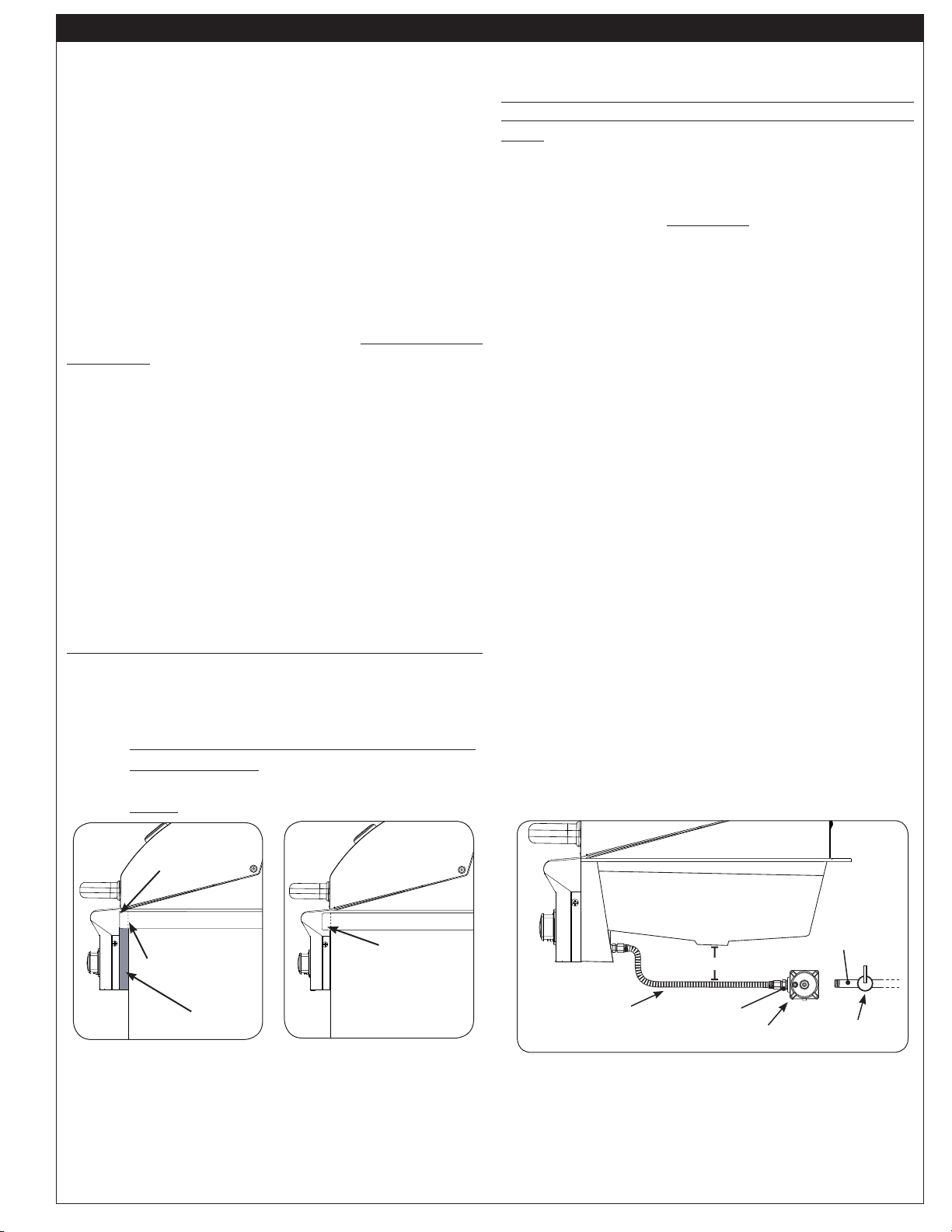
The control panel is designed to sit fl ush against the
enclosure front wall (see Fig. 13-2). If the non-combustible
countertop extends beyond the front wall, creating a
countertop overhang (see Fig. 13-1), it must be cut fl ush
with the front wall for the width of the control panel or
a gap will be created exposing the forward portions of
the left and right side grill fi re walls. See the MODEL
SPECIFICATIONS section.
Note: It is not necessary to remove the control panel
or knobs to install this unit.
CONNECT THE GAS SUPPLY
Always ensure the orifi ces and regulator are set for
the gas type your unit is to be installed to.
For propane cylinders:
For connecting a propane unit to a portable propane tank,
read the safety warnings and follow the instructions in the
section SAFE USE AND MAINTENANCE OF PROPANE
GAS CYLINDERS.
Note: When a propane cylinder is installed inside
of the enclosure, the guidelines found in the
ENCLOSURE REQUIREMENTS section
MUST be followed.
Fig. 13-1
Fig. 13-2
GAP CREATED
IDEAL
Flush-mounted
control panel
Proposed cut-
out in overhang
Countertop
Countertop
Overhang
Control panel
stops here
INSTALLATION
Fig. 13-3
Flex connector
(Grill)
Adapter
Regulator
Dedicated manual
shut-off valve
6" Grill clearance
Gas
supply
REV 0 - 1412011330
L-C2-437
Loading ...
Loading ...
Loading ...