Loading ...
Loading ...
Loading ...
LowerDriveBelt
NOTE: Proper removal of the lower drive belt requires
the removal of several tractor components. Read
through the following procedure prior to attempting ff to
determine if you feel you could successfully complete it.
If you don't, see an authorized MTD service dealer to
have the belt changed.
IMPORTANT: Note the routing of the lower drive belt
around all the pulleys and the belt keepers BEFORE
performing the following steps.
Locate the variable-speed pulley through the
battery tray opening. See Figure 19.
Remove the variable-speed pulley by loosening the
hex bolt that secures it to the transmission. Use a
second wrench to hold the hex nut on the bottom
side of the pulley.
Slide the lower drive belt off of the varia ble-speed
pulley as you lift the pulley up and out through the
battery tray opening.
Remove the rear idler pulley from the double- idler
bracket while unrouting the belt from around both
the rear and the front idler pulley. Refer to Figure
19.
Remove the hex bolt from the center of the engine
pulley (or electric PTO clutch, if so equipped) and
gently lower it off of the engine crankshaft. Be
careful not to lose any washers or spacers which
may be found on top of the engine pulley.
IMPORTANT: When remounting the engine pulley (or
electric PTO clutch), torque the center hex bolt to
between 38 foot-pounds and 50 foot-pounds.
Remove the drive belt by feeding it from both ends
toward the front idler pulley on the double-idler
bracket. See Figure 19.
Reassemble by following the above steps in
reverse order.
Route the replacement belt around the pulleys, belt
keepers and keeper pins EXACTLY as the old one
was routed. Refer to Figure 19.
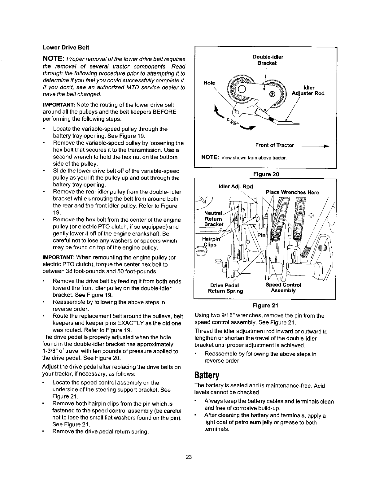
The drive pedal is properly adjusted when the hole
found in the double-idler bracket has approximately
1-3/8" of travel with ten pounds of pressure applied to
the drive pedal. See Figure 20.
Adjust the drive pedal after replacing the drive belts on
your tractor, if necessary, as follows:
Locate the speed control assembly on the
underside of the steering support bracket. See
Figure 21.
Remove both hairpin clips from the pin which is
fastened to the speed control assembly (be careful
not to lose the small flat washers found on the pin).
See Figure 21.
Remove the drive pedal return spring.
Double-idler
Bracket
Hole _ AdjuldlerrRod
Front of Tractor
NOTE: Viewshownfrom abovetractor.
Figure 20
Idler Adj. Rod
\
Neutral J
Return
Bracket
lips
Drive Pedal Speed Control
Return Spring Assembly
Place Wrenches Here
Figure 21
Using two 9/16" wrenches, remove the pin from the
speed control assembly. See Figure 21.
Thread the idler adjustment rod inward or outward to
lengthen or shorten the travel of the double-idler
bracket until proper adjustment is achieved.
Reassemble by following the above steps in
reverse order.
Battery
The battery is sealed and is maintenance-free. Acid
levels cannot be checked.
Always keep the battery cables and terminals clean
and free of corrosive build-up.
After cleaning the battery and terminals, apply a
light coat of petroleum jelly or grease to both
terminals.
23
Loading ...
Loading ...
Loading ...