Loading ...
Loading ...
Loading ...
ParkingBrakeAdjustment
A
WARNING: Never attempt to adjust the
brakes while the engine is running. Always
disengage PTO, move shift lever into neutral
position, stop engine and remove key to
prevent unintended starting.
If the tractor does not come to a complete stop when
the brake pedal is completely depressed, or if the
tractor's rear wheels can roll with the parking brake
applied, the brake is in need of adjustment. The brake
disc can be found on the right side of the transmission
in the rear of the tractor. Adjust if necessary as follows:
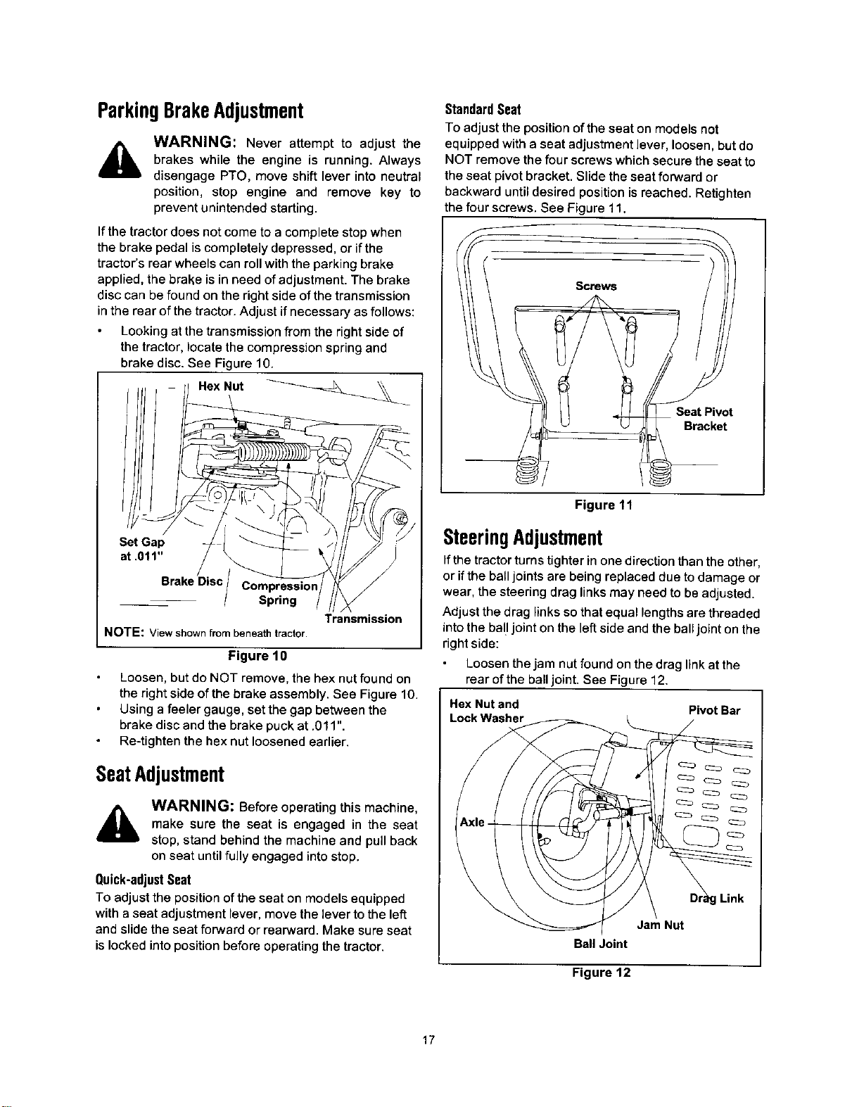
Looking at the transmission from the right side of
the tractor, locate the compression spring and
brake disc. See Figure 10.
Hex Nut _
Standard Seat
To adjust the position of the seat on models not
equipped with a seat adjustment lever, loosen, but do
NOT remove the four screws which secure the seat to
the seat pivot bracket. Slide the seat forward or
backward until desired position is reached. Retighten
the four screws. See Figure 11.
Screws
Seat Pivot
Bracket
Set Gap
at .011"
Brake Disc
Spring
NOTE: View shown from beneath tractor.
Transmission
Figure 10
Loosen, but do NOT remove, the hex nut found on
the right side of the brake assembly. See Figure 10.
Using a feeler gauge, set the gap between the
brake disc and the brake puck at .011".
Re-tighten the hex nut loosened earlier.
SeatAdjustment
A
WARNING: Before operating this machine,
make sure the seat is engaged in the seat
stop, stand behind the machine and pull back
on seat until fully engaged intostop.
Quick-adjustSeat
To adjust the position of the seat on models equipped
with a seat adjustment lever, move the lever to the left
and slide the seat forward or rearward. Make sure seat
is locked into position before operating the tractor.
Figure 11
SteeringAdjustment
Ifthe tractor turns tighter in one direction than the other,
or if the ball joints are being replaced due to damage or
wear, the steering drag links may need to be adjusted.
Adjust the drag links so that equal lengths are threaded
into the ball joint on the left side and the ball joint on the
right side:
Loosen the jam nut found on the drag linkat the
rear of the ball joint. See Figure 12.
Hex Nut and Pivot Bar
Lock Washer
g Link
Jam Nut
Bali Joint
Figure 12
17
Loading ...
Loading ...
Loading ...