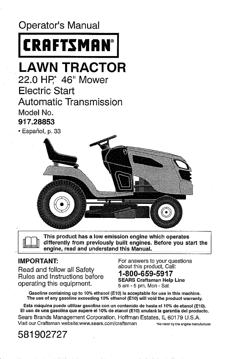
Operator's Manual
22.0 HP,* 46" Mower
Electric Start
Automatic Transmission
Model No.
917.28853
• EspaSol, p. 33
IMPORTANT: For answers to your questions
about this product, Call:
Read and follow all Safety
Rules and Instructions before 1-800-659-5917
SEARS Craftsman Help Line
operating this equipment. 5 am - 5 pro, Mon- Sat
Gasoline containing up to t0% ethanol (EIO) is acceptable for use in this machine.
The use of any gasoline exceeding 10% ethanol (El0) will void the product warranty.
Esta mdquina puede utilizar gasolina con an contenido de hasta el 10% de etanol (ElO).
El uso de una gasolina que supere el 10% de etanol (EIO) anulard la garantia del producto,
Sears Brands Management Corporation, Hoffman Estates, IL 60179 U.S.A.
Visit our Craftsman website:we_v.sears,com/craftsman _As rated bytheenginemar_ufacture_
581902727
Warranty ................................................ 2
Safety Rules .......................................... 3
Product Specifications ........................... 6
Assembly/Pre-Operation ....................... 7
Operation ............................................... 9
Maintenance Schedule ........................ 16
Maintenance ........................................ 16
Service and Adjustments ..................... 21
Storage ................................................ 27
Troubleshooting ................................... 28
Sears Service ........................ Back Cover
Craftsman Riding Equipment Warranty
CRAFTSMAN FULL WARRANTY
FOR TWO YEARS from the date of purchase, all non-expendable parts of this riding equipment are
warranted against any defects in material or workmanship. A defective non-expendable part will
receive free in-home repair or replacement if repair is impossible.
FOR .FIVE YEARS from the date of purchase, the frame and front axle of this ridingequipment are
warranted against any defects in material or workmanship. A defective frame or front axle will receive
free in-home repair or replacement if repair is impossible.
FOR 90 DAYS from the date of purchase, the battery (an expendable part) of this riding equipment
is warranted against any defects in material or workmanship (our testing proves that it will not hold a
charge). A defective battery will receive free in-home replacement.
ADDITIONAL LIFETIME LIMITED WARRANTY on CAST IRON FRONT AXLE (if equipped)
FOR AS LONG AS IT IS USED bythe original owner after the fifth year from the date of purchase, the
cast iron front axle (if equipped) of this riding equipment is warranted against any defects in material or
workmanship. With proof of purchase, a defective cast front axfe will receive free in-home replacement.
WARRANTY SERVICE
For warranty coverage details to obtain free repair or replacement, call 1-800-659-5917 or visitthe
web site: www.craftsman.com
In all cases above, if part repair or replacement is impossibIe, the riding equipment will be replaced
free of charge with the same or an equivalent model.
All of the above warranty coverage is void if this riding equipment is ever used while providing
commercial services or if rented to another person.
This warranty covers ONLY defects in material and workmanship. Warranty coverage does NOT
include:
• Expendable parts (except battery) that can wear out from normaEuse within the warranty period,
including but not limited to blades, spark plugs, air cleaners, belts, and oil filters.
• Standard maintenance servicing, oil changes, or tune-ups,
• Tire replacement or repair caused by punctures from outside objects, such as nails, thorns,
stumps, or glass.
.....-Tireo_wheeI=replacementor repair resultingfrom normal wear, accident; or improper operation or ........
maintenance.
• Repairs necessary because of operator abuse, including but not limited to damage caused by
towing objects beyond the capability of the riding equipment, impacting objects that bend the
frame, axle assembly or crankshaft, or over-speeding the engine.
• Repairs necessary because of operator negligence, including but not limited to, electrical and
mechanical damage caused by improper storage, failure to use the proper grade and amount
of engine oil, failure to keep the deck clear of flammable debris, or failure to maintain the riding
equipment according to the instructions contained in the operator's manual.
• Engine (fuel system) cleaning or repairs caused by fueI determined to be contaminated or oxidized
(stale). In general, fuel should be used within 30 days of its purchasedate.
• Normal deterioration and wear of the exterior finishes, or product label replacement.
This warranty gives you specific legal rights, and you may also have other rights which vary from
state to state.
Sears Brands Management Corporation, Hoffman Estates, IL 60179
_IkDANGER: This cutting machine is capable of amputating hands and feet and
throwing objects. Failure to observe the following safety instructions could result
in serious injury or death.
_WARNING: In orderto prevent acciden-
tal starting when setting up, transporting,
adjusting or making repairs, always discon-
nect spark plug wire and place wire where
it cannot contact spark plug.
_WARNING: Do not coast down a hill in
neutral you may lose control of the tractor.
_,WARNING: Tow only the attachments
that are recommended by and comply with
specifications of the manufacturer of your
tractor. Use common sense when towing.
Operate only at the lowest possible speed
when on a slope. Too heavy of a load,while
on a slope, is dangerous. Tires can lose
traction with the ground and cause you to
lose control of your tractor.
_.WARNING: Engine exhaust, some of
its constituents, and certain vehicle compo-
nents contain or emit chemicals known to
the State of California to cause cancer and
birth defects or other reproductive harm,
h(_WARNING: Battery posts, terminals and
related accessories contain lead and lead
compounds, chemicals known to the State of
California to cause cancer and birth defects
or other reproductive harm. Wash bands
after bandling,
I. GENERAL OPERATION
• Read, understand, and fol]owa]l instruc-
tions on the machine and in the manual
before starting.
• Never direct discharged materialtoward
anyone. Avoid discharging material
against a wall or obstruction. Material
may ricochet back toward the operator.
Stop the blades when crossing gravel
surfaces.
• Do not operate machine without the en-
tire grass catcher, discharge chute, or
othersafetydevices inplaceand working.
• Slow down before turning.
• Never leave a running machine unat-
tended. Always turn off blades, set
parking brake, stop engine, and remove
keys before dismounting.
• Disengage blades when not mowing.
Shut off engine and wait for all parts to
come to a complete stop before cleaning
the machine, removingthe grass catcher,
or unclogging the discharge chute.
• Operate machine only in daytight orgood
artificial light.
• Do not operate the machine while under
the influence of alcohol or drugs.
• Watch for traffic when operatingnear or
crossing roadways.
• Useextracarewhen loading or unloading
the machine into a trailer or truck.
• Always wear eye protection when operat-
ingmachine.
• Data indicates that operators, age 60
years and above, are involved in a large
percentage of riding mower-related inju-
ries, These operators should evaluate
their ability to operate the riding mower
safely enoughto protect themselves and
others from serious injury.
• Do not put hands or feet near rotating . _ .
_^._..... ._^. _. .... _,;_^ _-.... ,_ t-ollowthe manufacturer's recommenda-
_dl I._ UI UIIU_I _.llI;__ II l_;_l III I_, f_3_;_lO _I_I , , ,
tton for wheelwelghts or counterwetghts
...........of file discharge opening a:taii iimes: .................. ;......
• Only allow responsible adults, who are
familiar with the instructions, to operate
the machine.
• Clear the area of objects such as rocks,
toys, wire, etc., which could be picked
up and thrown by the blades.
• Be sure the area is clear of bystanders
beforeoperating. Stop machine if anyone
enters the area.
• Never carry passengers,
• Do not mowin reverse unless absolutely
necessary, Always tookdown and behind
before and while backing.
Keep machine free of grass, leaves or
other debris build-up which can touch hot
exhaust/engine parts and burn. Do not
allow the mower to plow leaves or other
debris which can cause build-up to oc-
cur. Clean any oil or fuel spillage before
operating or storing the machine. Allow
machine to cool before storage.
Ih SLOPE OPERATION
Slopes are a major factor related to loss of
control and tip-over accidents, which can
result in severe injury or death. Operation
on all slopes requires extra caution. If you
cannot back upthe slope or ifyoufeel uneasy
on it, do not mow it.
• Mow up and down slopes, not across.
• Watch for holes, ruts, bumps, rocks, or
other hidden objects. Uneven terrain
could overturn the machine. Tall grass
can hide obstacles.
• Choose a low ground speed so that you
wilt not have to stop or shift while onthe
slope.
• Do not mow on wet grass. Tires may lose
traction.
Always keep the machine in gear when
going down slopes. Do not shiftto neutral
and coast downhill.
• Avoid starting, stopping, or turning on a
slope, lfthetires Iosetraction, disengage
the blades and proceed slowly straight
down the slope.
• Keep all movement on the slopes slow
and gradual. Do not make sudden
changes in speed or direction, which
could cause the machine to roll over.
• Use extra care while operating macliine
with grass catchers orother attachments;
they can affect the stability of the ma-
chine. Do no use on steep slopes.
• Do not try to stabilize the machine by
putting your foot on the ground.
- Do not mow near drop-offs, ditches,
or embankments. The machine could
suddenly roll over if a wheel is over the
edge or if the edge caves in.
llh CHILDREN
• Keep children out of the mowing area
and in the watchful care of a responsible
adult other than the operator.
• Be alert and turn machine off if a child
enters the area.
• Before and while backing, look behind
and down for small children.
, Never carrychildren, even withthe blades
shut off. They mayfalloff and be seriously
injured or interfere with safe machine
operation. Children who have been given
rides in the past may suddenly appear in
the mowing area for another ride and be
run over or backed over by the machine.
• Never allow children to operate the ma-
chine.
• Use extra care when approaching blind
corners, shrubs, trees, or other objects
that may block your view of a child.
IV. TOWING
• Tow only with a machine that has a hitch
designed for towing. Donot attach towed
equipment except at the hitch point.
• Followthemanufacturer'srecommenda-
tion for weight limitsfor towed equipment
and towing on slopes.
• Never allow children or others in or on
towed equipment,
• On slopes, theweight ofthe towed equip-
ment may cause loss of traction and loss
of control.
• Travel slowly and allow extra distance to
stop.
V. SERVICE
SAFE HANDLING OF GASOLINE
To avoid personal injury or property dam-
age, use extreme care in handling gasoline.
Gasoline is extremely flammable and the
,, vapors are explosive.
_I_.WARNING: CHILDRENCAN BE INJURED.........• Extinguish all cigarettes; cigars; pipes, .......
BYTHISEQUIPMENT.The American Acade- and other sources of ignition,
my of Pediatrics recommends that children
be a minimum of 12 year of age before op-
erating a pedestrian controlled lawn mower
and a minimum of 16 years of age before
operating a riding lawn mower.
Tragic accidents can occur if the operator
is not alert to the presence of children.
Children are often attracted to the machine
and the mowing activity. Never assume
that children will remain where you last
saw them.
4
Use only approved gasoline container.
• Never remove gas cap or add fuel with
the engine running, Allow engine to cool
before refueling.
• Never fuel the machine indoors.
• Neverstorethemachineorfuelcontainer
where there is an open flame, spark, or
pilot light such as on a water heater or
other appliances.
• Never fill containers inside a vehicle or
on a truck ortrailer bed with plastic liner.
Always place containers on the ground
away from your vehicle when filling.
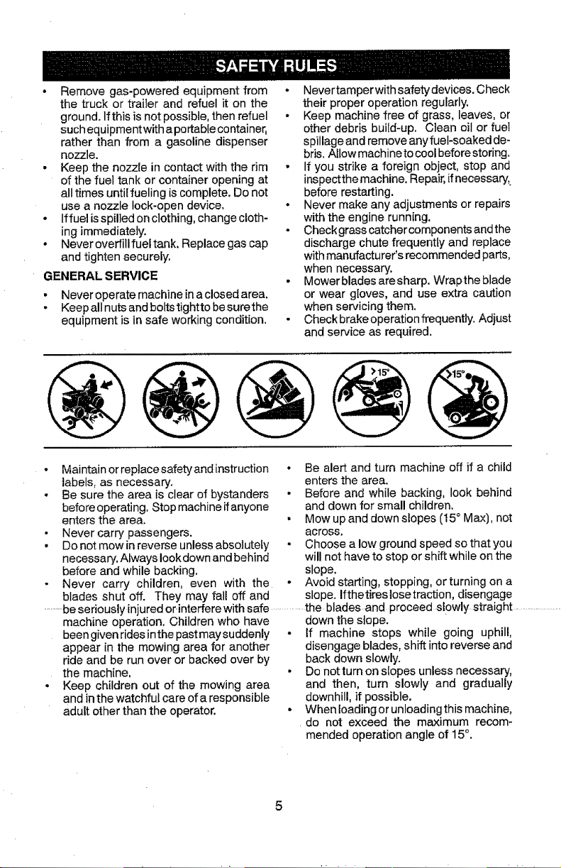
• Removegas-poweredequipmentfrom
thetruckortrailerandrefuelit onthe
ground.Ifthisisnotpossible,thenrefuel
suchequipmentwithaportablecontainer,
ratherthanfroma gasolinedispenser
nozzle.
• Keepthenozzleincontactwiththerim
ofthefueltankorcontaineropeningat
alltimesuntilfuelingiscomplete.Donot
useanozzlelock-opendevice,
• Iffuelisspilledonclothing,changecloth-
ingimmediately.
° Neveroverfillfueltank.Replacegascap
andtightensecurely,
GENERAL SERVICE
• Never operate machine in a closed area.
• Keep all nuts and boltstightto be surethe
equipment is in safe working condition.
o
Nevertamper with safety devices. Check
their proper operation regularly.
Keep machine free of grass, leaves, or
other debris build-up. Clean oil or fuel
spillage and remove any fuel-soaked de-
bris. Allow machine to cool before storing.
If you strike a foreign object, stop and
inspectthe machine. Repair, if necessary;
before restarting.
Never make any adjustments or repairs
with the engine running.
Check grass catcher components and the
discharge chute frequently and replace
withmanufacturer's recommended parts,
when necessary.
Mowerblades aresharp. Wrapthe blade
or wear gloves, and use extra caution
when servicing them.
Check brake operation frequently. Adjust
and service as required.
• Maintain or replacesafety and instruction
labels, as necessary.
• Be sure the area is clear of bystanders
before operating, Stop machine if anyone
enters the area.
• Never carry passengers.
• Do not mowin reverse unless absolutely
necessary, Always look down and behind
before and while backing,
Never carry children, even with the
• Be alert and turn machine off if a child
enters the area.
• Before and while backing, look behind
and down for small children.
• Mow up and down slopes (I5 ° Max), not
across.
Choose a low ground speed so that you
will not have to stop or shift while on the
slope,
• Avoid starting, stopping, or turning on a
blades shut off. They may fall off and slope. Ifthetireslosetraction, disengage
..........be seriously injured or-interfere with safe ...............the blades and proceed slowly straight ..........................
machine operation, Children who have down the slope.
been givenrides inthe past may suddenly
appear in the mowing area for another
ride and be run over or backed over by
the machine.
Keep children out of the mowing area
and inthe watchful care of a responsible
adult other than the operator.
• If machine stops while going uphill,
disengage blades, shift into reverse and
back down slowly.
• Do notturn on slopes unless necessary,
and then, turn slowly and gradually
downhill, if possible.
• Whenloadingor unloadingthis machine,
do not exceed the maximum recom-
mended operation angle of 15°.

PRODUCT SPECIFICATIONS
Gasoline Capacity 2,5 GaI{ons/9,46 L
and type: Regular Unteaded
Oil "5/pe: SAE 10W30 (above 32°F/0°C
(API: SG-SL) SAE 5W30 (below 32°F/0+C
Oil Capacity: W] Fi{ter: 51 Oz+/t ,5 L
W/out Filter" 35 OzJ1,05 L
Spark Plug: Champion RC12YC
(Gap: .030"/0.76 mm)
Charging 15 Amps @ 3600 RPM
System:
Battery: Amp/Hr: 28
Min. CCA: 230
Case size: UIR
Blade Bolt Torque: 45+55 Ft. LbsJ62-75 Nm
CONGRATULATIONS onyour purchase of
a new tractor, tt has been designed, engi-
neered and manufactured to give you the best
possible dependability and performance.
Should you experience any problem youcan-
not easily remedy, please contact aSears or
other qualified service center. We have com-
petent, well-trained representatives and the
proper tools to service or repair this tractor.
Please read and retain this manual. The
instructions will enable you to assemble
and maintain yourtractor properly. Always
observe the "SAFETY RULES".
CUSTOMER RESPONSIBILITIES
• Read and observe the safety rules.
• Follow a regular schedule in maintaining,
caring for and using your tractor.
° Follow instructions under "Maintenance"
and "Storage" sections of this manual.
• Wear proper Personal Protective Equip-
ment (PPE) while operating this machine,
including(at a minimum) sturdy footwear,
Inthe state of Californiathe above isrequired
by law (Section 4442 of the California Public
Resources Code). Other states may have
similar laws. Federal laws apply on federal
lands. A spark arrester for the muffler is
available through your nearest Sears service
center (See REPAIR PARTS manual).
REPAIR PROTECTION AGREEMENTS
Congratulations on making a smart pur-
chase. Your new Craftsman® product is
designed and manufactured for years of
dependable operation. But like all products,
itmay require repair from timeto time.That's
when having a Repair Protection Agreement
can save you money and aggravation.
Purchase a Repair Protection Agreement
now and protect yourself from unexpected
hassle and expense.
Here's what's includedin the Agreement:
• Expertservice byour 12,000 professional
repair specialists.
• Unlimited service and no chargefor parts
and labor on all covered repairs.
• Product replacement if your covered
product can't be fixed.
• Discount of 10% from regular price of
service and service-related parts not
covered by the agreement; also, 10% off
regular price of preventive maintenance
check.
, Fast help by phone - phone support
from a Sears representative on products
requiring in-home repair, plus convenient
repair scheduling.
Once you purchase the Agreement, a simple
phone call is all that it takes for you to sched-
ule service. You can call anytime day or night,
or schedule a service appointment online.
eye protect!on, and hearing protection. Do Sears has over 12,000 professional repair
•• _lways letsomeone knowyou are outside million quality parts and accessories. That's
mowing, the kind of professionalism you can count on
_WARNING: This tractor isequipped with
an internal combustion engine and should
not be used on or near any unimproved
forest-covered, brush-covered or grass-
covered land unless the engine's exhaust
system is equipped with a spark arrester
meeting applicable local or state laws (if
any). if a spark arrester is used, it should
be maintained in effective working order by
the operator.
to help prolong the life of your new purchase
for years to come. Purchase your Repair
Protection Agreement today!
Some limitations and exclusions apply.
For prices and additional information cell
1-800-827-6655.
SEARS INSTALLATION SERVICE
For Sears professional installation of home
appliances, garage door openers, water
heaters, and other major home items, in the
U.S.A. call 1-8004-MY-HOME®
Slope Sheet
Keys _
(1) Quick
KW(_) _i Connect
Your new tractor has been assembled at the factory with the exception of those parts left
unassembled for shipping purposes.
TOOLS REQUIRED FOR ASSEMBLY Label
A socket wrench set will make assembly
easier. Standard wrench sizes are listed.
(1) 1/2" wrench Tire pressure gauge
(2) 7/16" wrenches Utility knife
Pliers
When right or left hand is mentioned in this
manual, itmeanswhenyou areintheoperating
position (seated behind the steering wheel).
TO REMOVE TRACTOR FROM
CARTON
UNPACK CARTON
• Remove all accessible loose parts and
parts cartons from carton.
• Cut along dotted lines on all four panels
of carton. Remove end panels and lay
side panels flat.
• Check for any additional loose parts or
cartons and remove.
BEFORE REMOVING TRACTOR
....................FROM SKID
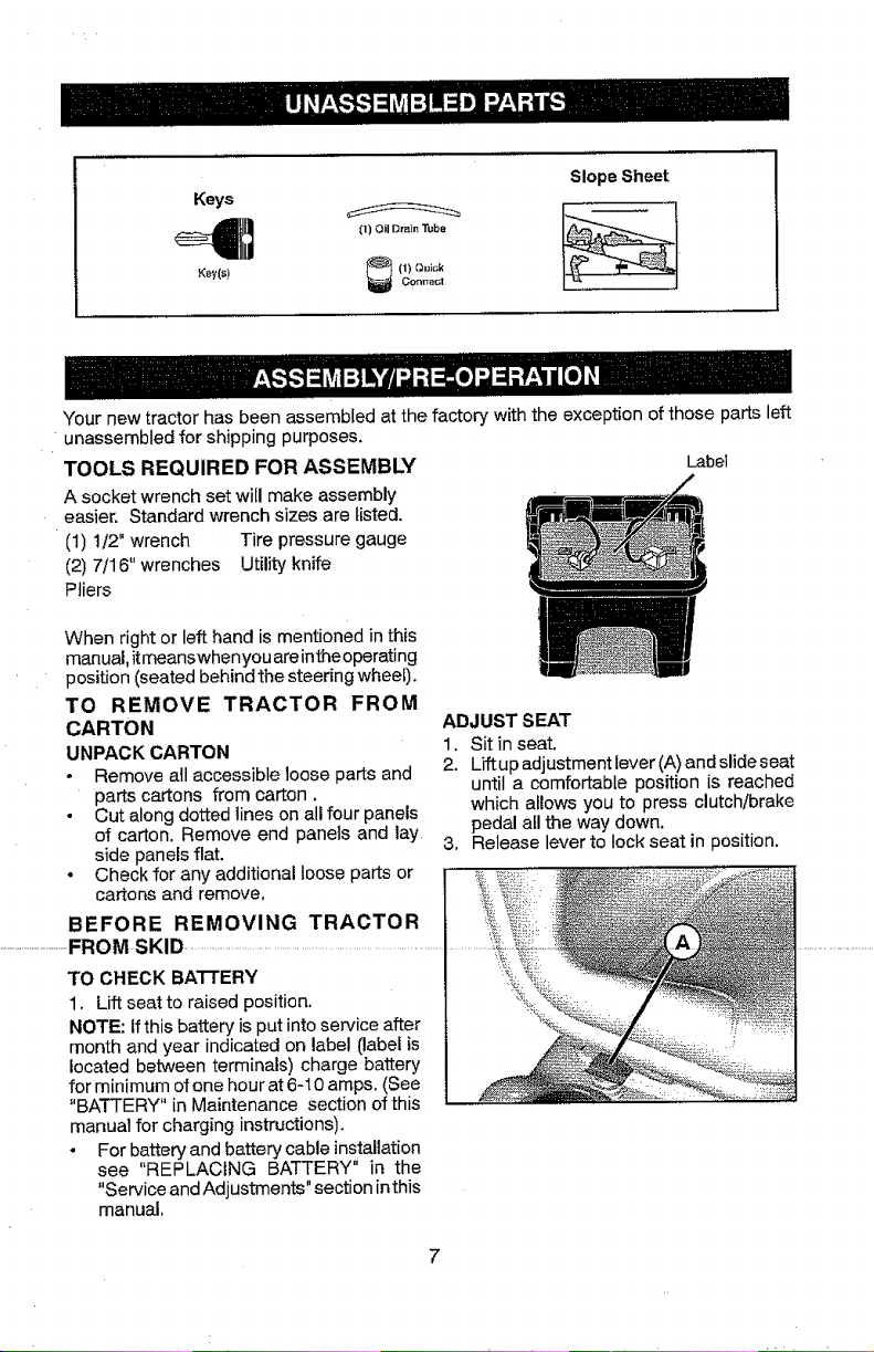
TO CHECK BATTERY
1. Lift seat to raised position.
NOTE: If this battery is put into service after
month and year indicated on label (label is
located between terminals) charge battery
for minimum of one hour at 6-10 amps. (See
"BATTERY" in Maintenance section of this
manual for charging instructions).
• For battery and battery cable installation
see "REPLACING BATTERY" in the
"Service and Adjustments" section in this
manual,
ADJUST SEAT
1. Sit in seat.
2. Lift up adjustment lever (A)and slide seat
until a comfortable position is reached
which allows you to press clutch/brake
pedal all the way down.
3. Release lever to lock seat in 3osition.
NOTE: You may now roll your tractor off the
skid, Followthe appropriate instruction below
to remove the tractor from the skid.
WARNING: Before starting, read, un-
derstand and follow al! instructions in the
Operation section of this manual. Be sure
tractor is in a well-ventilated area. Be sure
the area in front of tractor is clear of other
people and objects.
TO ROLL TRACTOR OFF SKID (See
Operation section for location and
function of controls)
1. Raise attachment liftlever to itshighest
position.
2. Release parking brake by depressing
brake pedal.
3. Place freewheel control in disengaged
position to disengage transmission (See
"TO TRANSPORT" inthe Operation sec-
tion of this manual).
4. Roll tractor forward off skid.
5. Remove banding holding the deflector
shield up against tractor,
Continue with the instructionsthat follow.
CHECK TIRE PRESSURE
The tires on your tractor were overinflated at
the factory for shipping purposes. Correct
tire pressure is important for best cutting
performance,
• Reduce tire pressure to PSI shown on
tires.
CHECK DECK LEVELNESS
For best cutting results, mower housing
should be properly leveled. See "TO LEVEL
MOWER" in the Service and Adjustments
section of this manual.
CHECK FOR PROPER POSITION OF
ALL BELTS
t_CHECKLIST
Before you operate your new tractor, we
wish to assure that you receive the best
performance and satisfaction from this
Quality Product.
Please review the following checklist:
J" All assembly instructions have been
completed.
!,/" No remaining loose parts in carton.
_/Battery is properlyprepared and charged.
1,/" Seat is adjusted comfortably and tight-
ened securely.
_/" All tires are properly inflated. (For ship-
ping purposes, thetires were overinflated
at the factory).
_/f Be sure mower deck is properly leveled
side-to-side/front-to-rear for best cutting
results. (Tires must be properly inflated
for leveling).
Vf Check mower and drive belts. Be sure
they are routed properly around pulleys
and inside all belt keepers.
_f Check wiring. See that all connections
are still secure and wires are properly
clamped.
_/" Before driving tractor, be sure freewheel
control is in "transmission engaged"
position (see "TO TRANSPORT" in the
Operation section of this manual).
While learning howto use your tractor, payex-
tra attention to the following important items:
_f Engine oil is at proper level,
J" Fueltank is filled with fresh, clean, regular
unleaded gasoline.
J Become familiar with all controls, their
location and function, Operate them
before you start the engine,
v f Be sure brake system is in safeoperating
condition.
See the figures that are shown for replacing _ Be sure Onerator Presence S_,stemand
"motion a:ndmoWetbladedrivebeltsirithe .............Reverse C_neration System ('F_OS_are ......
Service andAdjustments section ofthis man- _ _ _
working properly (See the Operation and
ual. Verify that the belts are routed correctly. Maintenance sections in this manual).
CHECK BRAKE SYSTEM
After you learn how to operate your tractor,
check to seethatthe brake is operating prop-
erly, See"TO CHECK BRAKE" inthe Service
and Adjustments section of this manual.
J" It is important to purge the transmission
before operating your tractor for the first
time. Fol!owproper startingand transmis-
sion purging instructions (See'%0 START
ENGINE"and "PURGETPdkNSMISSION"
inthe Operation section of this manual).
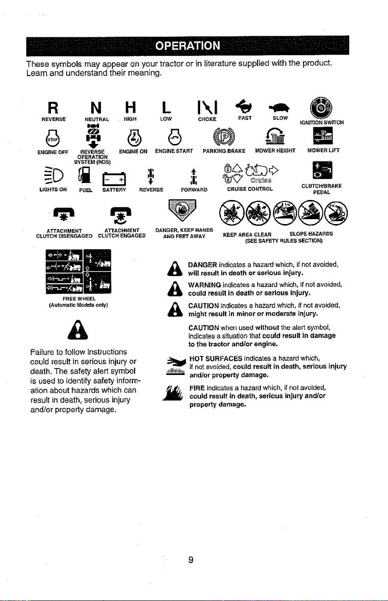
Thesesymbolsmayappearonyourtractororinliteraturesuppliedwiththeproduct,
Learnandunderstandtheirmeaning.
R N H L
REVERSE NEUTRAL HIGH LOW CHOKE FAST SLOW
ENGINE OFF REVERSE ENGINE ON ENGINE START PARKING BRAKE MOWER HEIGHT
OPERATION
SYSTEM(ROe)
CRUISE CONTROL
LIGHTS ON FUEL BA'n'ERY REVERSE FORWARD
ATrACHMENT ATTACHf_ENT DANGER, KEEP HANDS
CLUTCH DISENGAGED CLUTCH ENGAGES AND FEETAWAY
IGNITION swITCH
MOWERL[FT
GLUTCHIBRAKE
PEDAL
KEEP AREA CLEAR SLOPE HAZARDS
_EESAFETYRULES SECTION)
FREEWHEEL
(Automatic Models only)
Failure to follow instructions
could result in serious injury or
death. The safety alert symbol
is used to identify safety inform-
ation about hazards which can
result in death, serious injury
and/or property damage.
&
&
&
DANGER indicates a hazard which, if not avoided,
will result in death or serious injury.
WARNING indicates a hazard which, if not avoided,
could result in death or serious injury,
CAUTION indicates a hazard which, if not avoided,
might result in minor or moderate injury.
CAUTION when used without the alert symbol,
indicates a situation that could result in damage
to the tractor and/or engine.
HOT SURFACES indicates a hazard which,
if not avoided, could result in death, serious injury
and/or property damage.
FIRE indicates a hazard which, if not avoided,
could result in death, serious injury and/or
property damage,
9
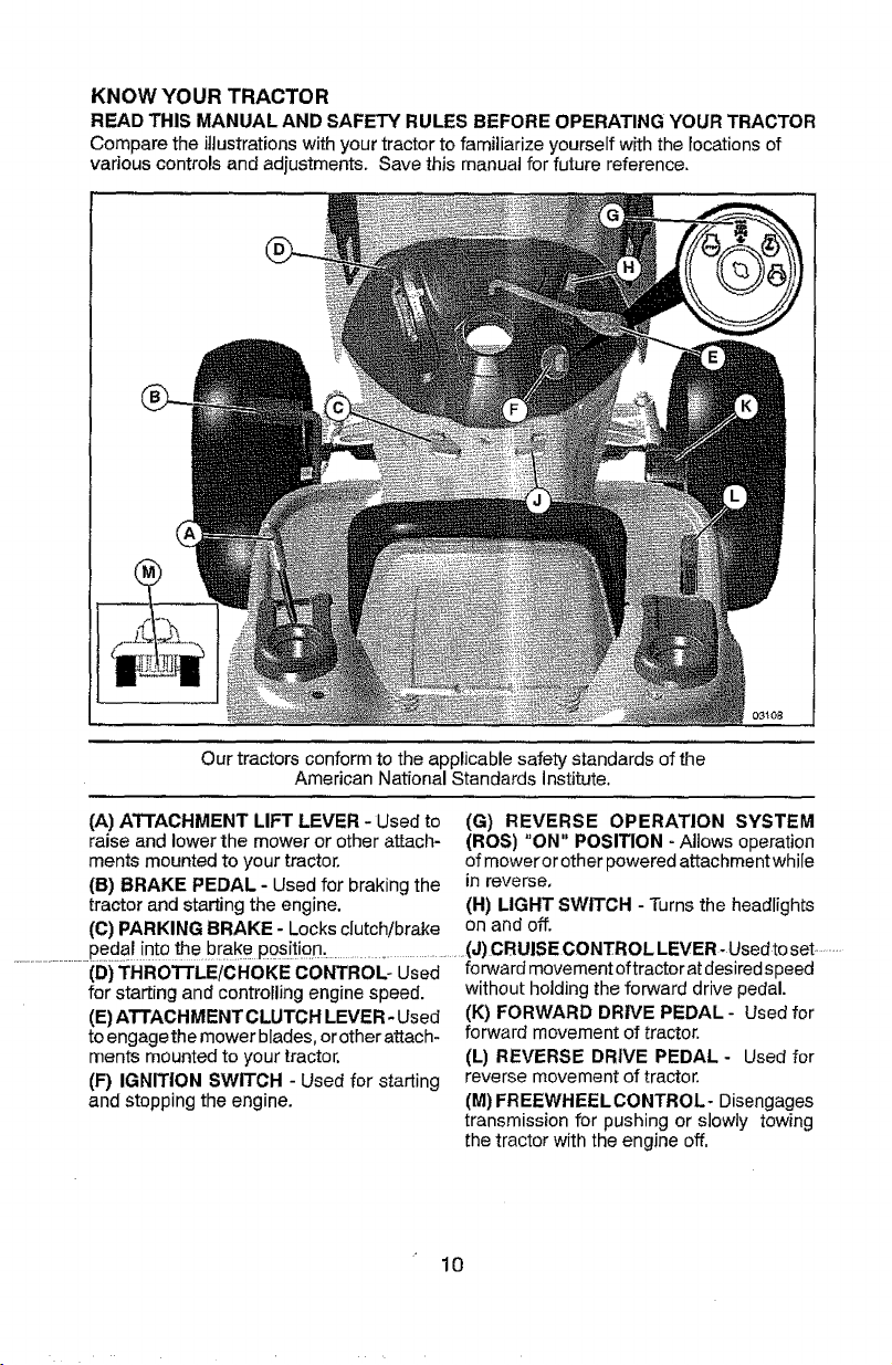
KNOW YO UR TRACTO R
READ THIS MANUAL AND SAFETY RULES BEFORE OPERATING YOUR TRACTOR
Compare the illustrations with your tractor to familiarize yourself with the locations of
various controls and adjustments. Save this manual for future reference,
Our tractors conform to the applJcable safety standards of the
American National Standards Institute.
(A) ATTACHMENT LIFT LEVER- Usedto (G) REVERSE OPERATION SYSTEM
raise and lower the mower or other attach- (ROS) "ON" POSITION - Allows operation
merits mounted to your tractor, of mowerorother powered attachmentwhile
(B) BRAKE PEDAL- Used for braking the in reverse.
tractor and starting the engine. (H) LIGHT SWITCH - Turns the headlights
(C) PARKING BRAKE- Locks clutch!brake on and off.
peda nto the brake position. (J) CRUISE CONTROL LEVER- Usedto set........
(D) THROTTLE/CHOKECONTROL- Used forwardmovementoftractoratdesiredspeed
for starting and controlling engine speed.
(E) ATTACHMENT CLUTCH LEVER- Used
to engagethe mower blades, or other attach-
ments mounted to your tractor.
(F) IGNITION SWITCH - Used for starting
and stopping the engine.
without holding the forward drive pedal.
(K) FORWARD DRIVE PEDAL- Used for
forward movement of tractor.
(L) REVERSE DRIVE PEDAL - Used for
reverse movement of tractor.
(M) FREEWHEELCONTROL- Disengages
transmission for pushing or slowly towing
the tractor with the engine off.
10
The operation of any tractor can result in foreign objects thrown into the eyes,
which can result in severe eyedamage. Always wear safety glasses or eye shields
while operatingyour tractor or performing any adjustments or repairs. We recom-
mend standard safety glasses orawidevision safety maskworn over spectacles.
HOW TO USE YOUR TRACTOR
TO SET PARKING BRAKE
Your tractor is equipped with an operator
presence sensing switch. When engine is
running, any attempt bythe operator to leave
the seat without first setting the parking brake
will shut off the engine,
1. Depress brake pedal (B) allthe way down
and hold.
2. Pull parking brake lever (C) up and hold,
release pressure from brake pedal (B),
then release parking brake lever. Pedal
should remain in brake position. Ensure
parking brake will hold tractor secure.
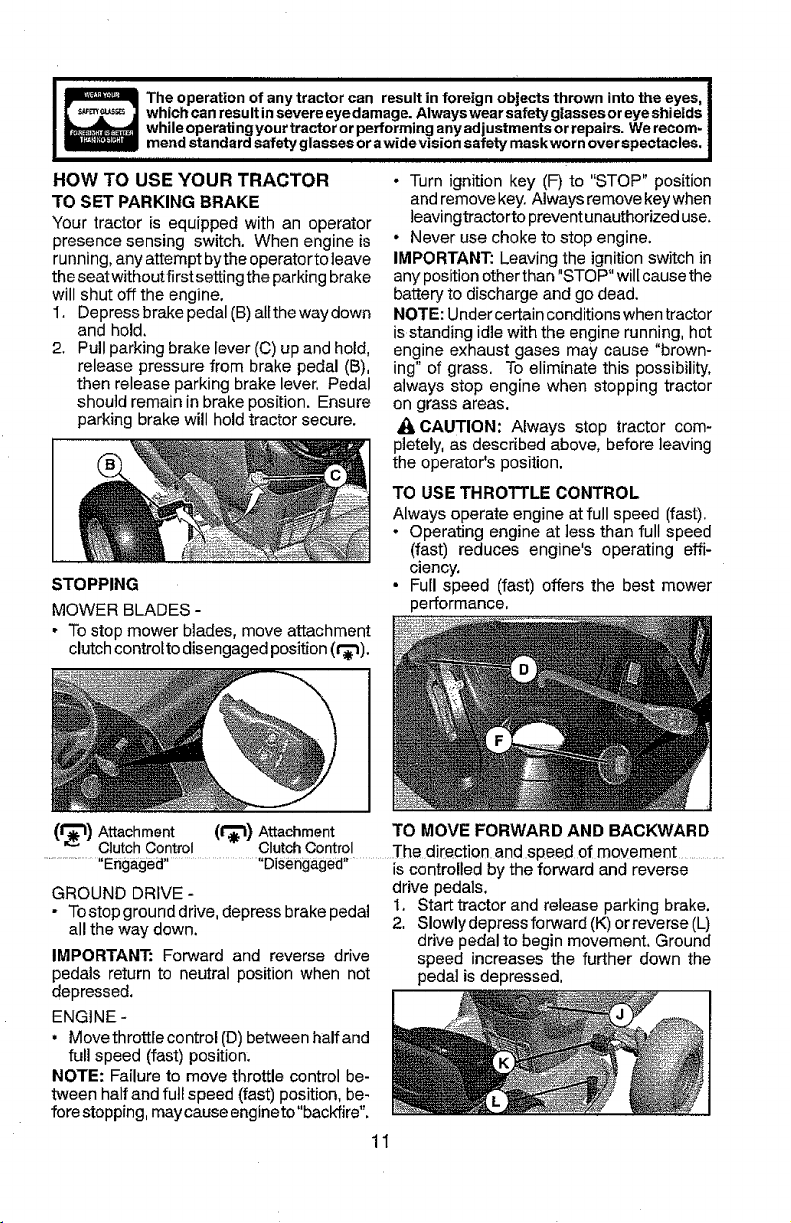
STOPPING
MOWER BLADES -
• To stop mower blades, move attachment
clutch controlto disengaged position (r_l).
• Turn ignition key (F) to "STOP" position
and remove key. Always remove key when
leavingtractor to prevent unauthorized use.
• Never use choke to stop engine.
IMPORTANT: Leaving the ignitionswitch in
any position other than "STOP" wilt cause the
battery to discharge and go dead.
NOTE: Under certain conditions when tractor
is standing idle with the engine running, hot
engine exhaust gases may cause "brown-
ing" of grass, To eliminate this possibility,
always stop engine when stopping tractor
on grass areas.
_1,CAUTION: Always stop tractor com-
pletely, as described above, before leaving
the operator's position.
TO USE THROTTLE CONTROL
Always operate engine at full speed (fast).
• Operating engine at less than full speed
(fast) reduces engine's operating effi-
ciency,
• Full speed (fast) offers the best mower
performance,
(_1_) Attachment (t_) Attachment TO MOVE FORWARD AND BACKWARD
.......... ,,Olutct_£ontr£!.....................OlutphOpntr?,!............]'he direction and speed of movement ..............
Lngagea LJisengagea
' is controlled by the forward and reverse
GROUND DRIVE-
- Tostop ground drive, depress brake pedal
all the way down.
IMPORTANT: Forward and reverse drive
pedals return to neutral position when not
depressed.
ENGINE -
, Move throttle control (D) between half and
full speed (.fast)position.
NOTE: Failure to move throttle control be-
tween half and full speed (fast) position, be-
fore stopping, may cause engineto"backfire".
drive pedals.
I, Start tractor and release parking brake.
2. Slowly depress forward (K) or reverse (L)
drive pedal to begin movement, Ground
speed increases the further down the
pedal is depressed,
1I
TO USE CRUISE CONTROL
The cruise control feature can be used for
forward travel only.
SYSTEM CHARACTERISTICS
The cruise controi should only be used
while mowing or transporting on relatively
smooth,straight surfaces. Other conditions
such astrimming at slow speeds may cause
the cruise control to disengage. Do not use
the cruise control on slopes, rough terrian
or while trimmimg or turning.
• With forward drive pedal (K) depressed to
desired speed, pull cruise control lever (J)
up and hold while lifting your foot off the
pedal, then release the lever,
To disengage the cruise control, depress the
brake pedal or tap on forward drive pedal.
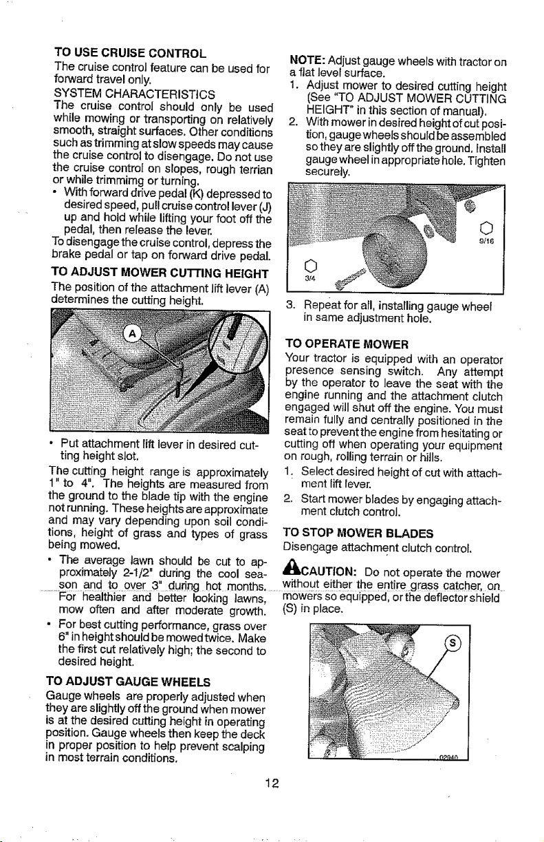
TO ADJUST MOWER CUTTING HEIGHT
The position of the attachment lift lever (A)
determines the cutting height.
• Put attachment lift lever in desired cut-
ting height slot,
The cutting height range is approximately
1" to 4". The heights are measured from
the ground to the blade tip with the engine
not running. These heights are approximate
and may vary depending upon soil condi-
tions, height of grass and types of grass
being mowed.
• The average town should be cut to ap-
NOTE: Adjust gauge wheels with tractor on
a flat level surface.
1. Adjust mower to desired cutting height
(See "TO ADJUST MOWER CUTTING
HEIGHT" in this section of manual),
2. With mower in desired height ofcut posi-
tion, gaugewheels should be assembled
so they are slightly off the ground, install
gauge wheel in appropriate hole.Tighten
securely,
©
3/4
3. Repeat for all, installinggauge wheel
in same adjustment hole.
TO OPERATE MOWER
Your tractor is equipped with an operator
presence sensing switch. Any attempt
by the operator to leave the seat with the
engine running and the attachment clutch
engaged will shut off the engine. You must
remain fully and centrally positionedin the
seat to prevent the engine from hesitating or
cutting off when operating your equipment
on rough, rolling terrain or hills,
1. Select desired height of cut with attach-
ment lift lever.
2. Start mower blades by engaging attach-
ment clutch control.
proximately 2-I/2" during the cool sea-
TO STOP MOWER BLADES
Disengage attachment clutch control,
_IbCAUTION: DOnot operate the mower
son and to over 3" durine hot months without either the entire grass catct)er,.an ....
..........For le0king tawnsl.........mowerS S0eqUipped_orthe defiector shield
mow often and after moderate growth. (S) in )lace.
For best cutting performance, grass over
6" inheightshould be mowedtwice. Make
the first cut relatively high; the second to
desired height.
TO ADJUST GAUGE WHEELS
Gauge wheels are properly adjusted when
they are slightly offthe ground when mower
is at the desired cutting height in operating
position. Gauge wheels then keep the deck
in proper position to help prevent scalping
in most terrain conditions.
12
REVERSE OPERATION SYSTEM (ROS)
Your tractor is equipped with a Reverse
Operation System (ROS). Any attempt by
theoperatorto travel inthereversedirection
with the attachment clutch engaged willshut
off the engine unless ignition key is placed
in the ROS "ON" position.
,_WARNING: Backing up with the at-
tachment clutch engaged while mowing is
strongly discouraged. Turningthe ROS "ON",
to allow reverse operation with the attach-
ment clutch engaged, should only be done
when the operator decides it is necessary to
reposition the machine with the attachment
engaged. Do not mow in reverse unless
absolutely necessary.
USING THE REVERSE OPERATION
SYSTEM -
Only use if you are certain no children or
other bystanders will enter the mowing area.
1, Depress brake pedal all the way down.
2. With engine running, turn ignition key
counterclockwise to ROS "ON" position,
3. Look down and behind before and while
backing.
4. Slowly depress reverse drive pedal to
start movement.
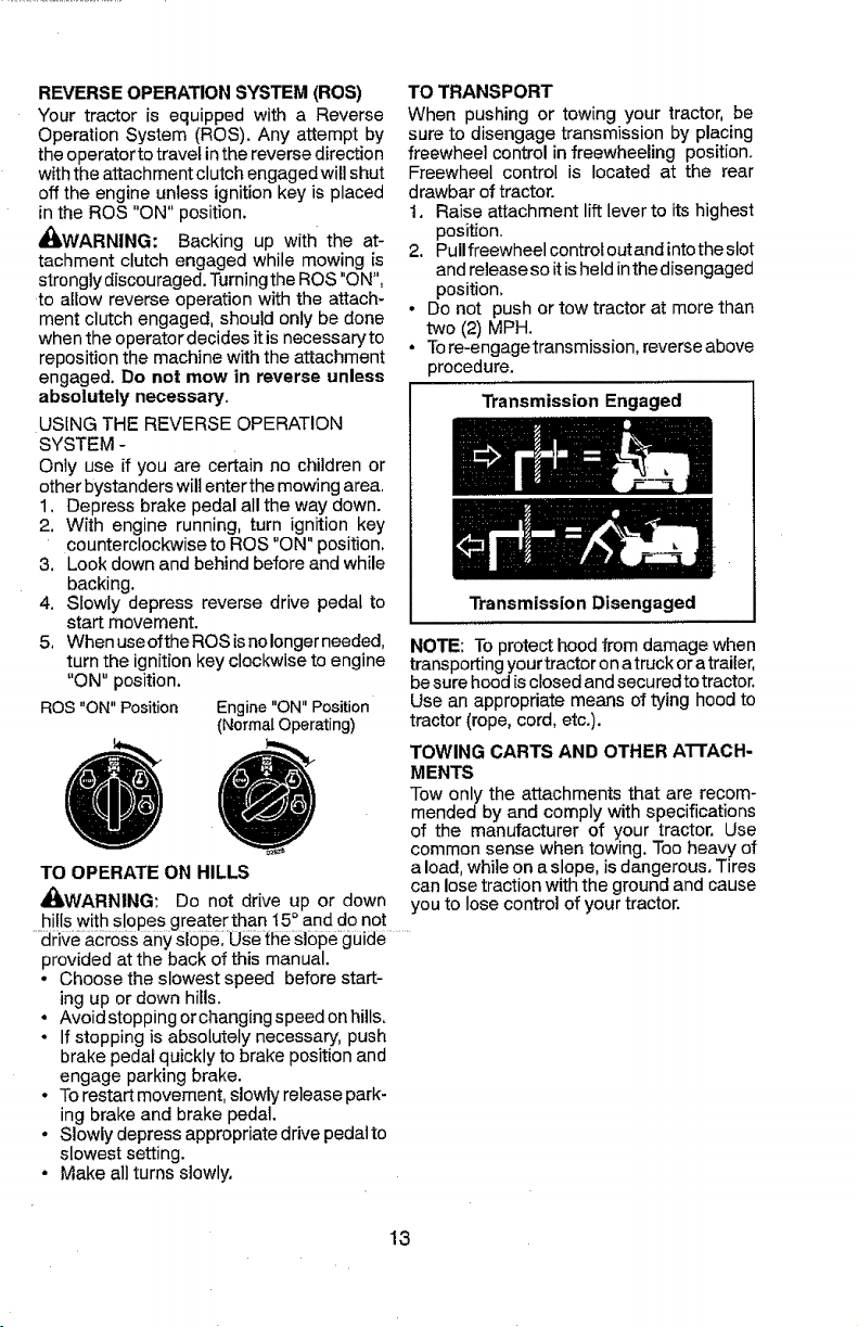
5, When useofthe ROS is nolonger needed,
turn the ignition key clockwise to engine
"ON" position,
ROS"ON" Position Engine"ON" Position
(NormalOperating)
TO OPERATE ON HILLS
AI_WARNING: Do not drive up or down
TO TRANSPORT
When pushing or towing your tractor, be
sureto disengage transmission by placing
freewheel control in freewheeling position.
Freewheel control is located at the rear
drawbar of tractor.
1. Raise attachment lift lever to its highest
position.
2. Pullfreewheel control out and into the slot
and release so it is held inthe disengaged
position,
* Do not push or tow tractor at more than
two (2) MPH.
o Tore-engagetransmission, reverse above
procedure.
Transmission Engaged
Transmission Disengaged
NOTE: To protect hood from damage when
transporting your tractor on a truck or a trailer,
be sure hood is closed and secured to tractor.
Use an appropriate means of tying hood to
tractor (rope, cord, etc.).
TOWING CARTS AND OTHER ATTACH-
MENTS
Tow only the attachments that are recom-
mended by and comply with specifications
of the manufacturer of your tractor. Use
common sense when towing. Too heavy of
a load, while on a slope, is dangerous, Tires
can lose traction with the ground and cause
you to lose control of your tractor.
hills with slopes greater than I5 ° and do not
provided at the back of this manual.
• Choose the slowest speed before start-
ing up or down hills.
. Avoid stopping orchanging speed on hills.
• If stopping is absolutely necessary, push
brake pedal quickly to brake position and
engage parking brake.
• To restart movement, slowly release park-
ing brake and brake pedal.
° Slowly depress appropriate drive pedal to
slowest setting.
• Make all turns slowly,
13
BEFORE STARTING THE ENGINE
CHECK ENGINE OIL LEVEL
The engine inyourtractor has been shipped,
from the factory, already filled with summer
weight oil,
1. Check engine oil with tractor on level
ground.
2. Remove oiIfi]lcap/dipstick andwipe clean,
reinsert the dipstick and screw cap tight,
wait for a few seconds, remove and read
oillevel, If necessary, add oil until "FULl"
markon dipstickis reached. Donotoverfil].
, For cold weather operation you should
change oil for easier starting (See the oil
viscosity chart inthe Maintenance section
of this manual).
• Tochangeengine oil, see the Maintenance
section inthis manual.
ADD GASOLINE
• Fill fueltank to bottom offiller neck. Do not
overfill, Usefresh, clean, regular unleaded
gasoline with a minimum of 87 octane.
(Use of leaded gasoline will increase car-
bon and lead oxide deposits and reduce
valve life). Do not mix oil with gasoline.
Purchasefuel inquantities thatcan beused
within 30 days to assure fuel freshness.
_CAUTION: Wipe off any spilled oil or
fuel. Do not store, spill or use gasoline near
an open flame.
IMPORTANT: When operating in tempera-
tures below 32°F(0°C), use fresh, clean
winter grade gasoline to help insure good
cold weather starting.
CAUTION: Alcohol blended fuels (called
gasohoi or using ethanol or methanol) can
attract moisture which leads to separation
and formation ofacids during storage. Acidic
gas candamagethe fuel system of an engine
while in storage. To avoid engine problems,
2. Sit on seat inoperating position, depress
brake pedal and set parking brake.
3. Move attachment clutch to disengaged
position.
4. Move throttle control to choke position.
NOTE: Before starting, read the warm and
cold starting procedures below.
5. Insert key into ignition and turn key
clockwise to start position and release
key as soon as engine starts. Do not run
starter continuously for more than fifteen
seconds per minute. If the engine does
not start after several attempts, move
throttle control to fast position, wait a
few minutes and try again. If engine still
does not start, move the throttle control
back to the choke position and retry,
WARM WEATHER STARTING
(50°F/10 ° C and above)
6. When engine starts, move the throttle
control to the fast position.
- The attachments and ground drive can
now be used. Ifthe engine does not accept
the load, restart the engine and allow it to
warm up for one minute using the choke
as described above.
COLD WEATHER STARTING
(50°F/10 ° C and below)
6. When engine starts, leave throttle controI
inchoke position until engine warms up
and begins to run roughly. Once rough
running begins, immediately move the
throttle controlto thefast position. Engine
warm-up maytake from several seconds
to several minutes (the colder the tem-
perature, the longer the warm-up).
AUTOMATIC TRANSMISSION WARM UP
Before driving the unit in cold weather, the
transmission should be warmed up as fol-
lows:
1. Be sure the tractor is on level ground,
the fuel system should be emptied before
............ " ............. 2;--Release-the parking brake- and let-the .........
storage of 30 days or longer. Drain the gas brake slowly returnto operating position.
tank, start the engine and let it run until the
fuel lines and carburetor are empty. Use
fresh fuel next season. See Storage Instruc-
tions for additional information, Never use
engine or carburetor cleaner products inthe
fuel tank or permanent damage may occur.
TO START ENGINE
When starting the engine for the first time or
if the engine has run out of fuel, it will take
extra cranking time to move fuel from the
tank to the engine.
1. Be sure freewheel control is in the trans-
mission engaged position.
3. Allow one minutefor transmission to
warm up. This can be done during the
engine warm up period.
• The attachments can also be used dur-
ing the engine warm-up period after the
transmission has been warmed up.
NOTE: If at a high altitude (above 3000 feet)
or in cold temperatures (below 32°F/0°C)
the carburetor fuel mixture may need to be
adjusted for best engine performance (see
"TO ADJUST CARBURETOR" inthe Service
and Adjustments section of this manual),
14
PURGE TRANSMISSION
_IbCAUTION: Never engage or disengage
freewheel lever while the engine is running,
Toensure properoperation and performance,
itis recommended that the transmission be
purged before operating tractor for the first
time. This procedurewill remove any trapped
air inside the transmission which may have
developed during shipping of your tractor.
IMPORTANT: Should your transmission
require removal for service or replacement,
itshould be purged after reinstallation before
operating the tractor.
1, Place tractor safely on a level surface -
that is clear of objects and open - with
engine off and parking brake set.
2. Disengage transmission by placing
freewheel control indisengaged position
(See "TO TRANSPORT" in this section
of manual).
3, Sitting in the tractor seat, start engine.
After the engine is running,move throttle
control to slow position, Disengage park-
ing brake.
_IbCAUTION: At any time, during step 4,
there may be movement of the ddve wheels.
4, Depress forward ddve pedalto fullforward
. position and holdforfive (5)seconds and
release pedal, Depress reverse drive
pedal to full reverse position and hold
for five (5) seconds and release pedal.
Repeat this procedure three (3) times.
5. Shutoff engine and set parking brake.
6, Engage transmission by placing free-
wheel control in engaged position (See
"TO TRANSPORT" in this section of
manual).
7. Sitting in the tractor seat, start engine,
MOWING TIPS
• Tire chains cannot be used when the
mower housing is attached to tractor.
• Mower should be properly leveled for best
mowing performance. See "TO LEVEL
MOWER HOUSING" in the Service and
Adjustments section of this manual.
• The left hand side of mower should be
used for trimming,
• Drivesothatclippings are discharged onto
the area that has already been cut. Have
the cut area to the right of the tractor. This
will result in a more even distribution of
clippings and more uniform cutting,
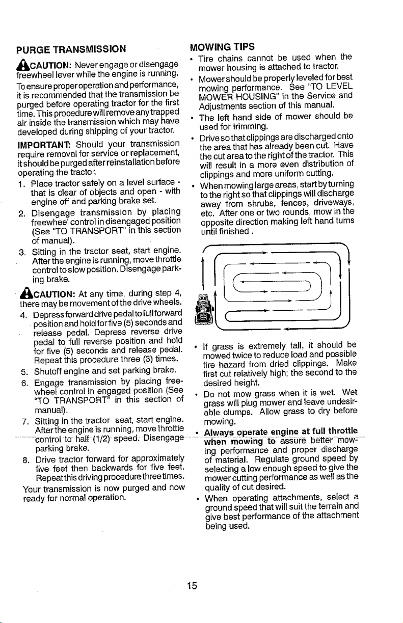
• When mowing large areas, start by turning
to the right so that clippings will discharge
away from shrubs, fences, driveways,
etc, After one or two rounds, mow in the
oppositedirection making left hand turns
until finished,
• If grass is extremely tall, it should be
mowed twice to reduce load and possible
fire hazard from dried clippings, Make
first cut relatively high; the second to the
desired height,
• Do not mow grass when it is wet. Wet
grass will plug mower and leave undesir-
able clumps. Allow grass to dry before
mowing.
After the engine is running, move throttle
8, Drive tractor forward for approximately
five feet then backwards for five feet,
Repeatthisdriving procedurethreetimes.
Your transmission is now purged and now
ready for normal operation.
...................,.,_,,_= ÷,_-h=[{t_/m. _,_4. r_ ................ ,.Always operate engine at full throttle
parking brake. " wi_en mowirigt0assi_re betterm0w: .....
ing performance and proper discharge
of material. Regulate ground speed by
selecting a low enough speed to give the
mower cutting performance as well as the
quality of cut desired.
• When operating attachments, select a
ground speed that will suitthe terrain and
give best performance of the attachment
being used.
15
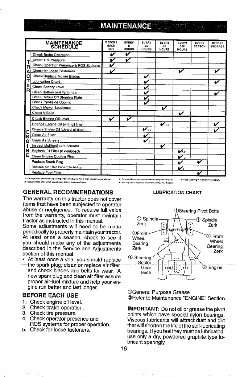
INTENANCE .....MA aE_R_ L'VERYEVERY EVERY ........EVERY EVERY BEFORE
SCHEDULE _ACH _ 25 Go _os s_soN S_OR,OE
USE HOURS HOURS HOURS HOURS
Cheek Brake Operation V' '" V " " '
.Check Tire Pr@ssure V _ V'
Check Operator Presence & ROS Systems I_
A L,Checkfor Loose,,Fasteners , ,V r V V"
C CheeldReplace Mower Blades 1_3
T Lubrication Chart _ if
_ .Chack Battery Leve'l
Clean Battery and Terminals V_, _,V
clean Debris Off Steering plate .... t,w#s
Check Transaxle Coo_ing _, '......
CheCk Mower,Levelness , ,, V r ....
Check V-SeIts if
i ,,,illH i i
Check Encline Oil Level ### V'
Change E,,n9 ne O (with oil filter) V'_,_ If
Change Engine 0{I (without _1 filter) V'12
,
i
_
_L
E Cle_,n Air" Fi!ter "V_" .....
G c_aan A_r screen V'_ .......
_] ,,!,_,spectMuffler/Spark Arrester if ........
Replace Oi[ Filter (if equipped) I1_,2
E clean E_ineCooliqgFi_ ' 11/:,
Replace Spark Plug ........ if V
Replace Air Filler Pap6r Cartridge _2 ,,
Replace Fuel Fil_er
GENERAL RECOMMENDATIONS LUBRICATIONCHART
The warrantyon thistractor does not cover
items that have been subjected to operator
abuse or negligence. To receive full value _Steering Pivot Bolts
from the warranty,operator must maintain _ ^ . /\
tractor as instructed inthis manual _ _p_ndie__l-_ Spindle
Some adjustments will need to be made z_erk _L-J.-:::_::_ Zerk
periodically to properly maintain your tractor, (_)Front ...--_" :." _'__-.... ....
At least once a season, check to see if Wheel _ _-.\ L ,4_l-i'oni
you should make any of the adiustments Bearing _Z:._:.'_."_\ k Wheet
described in the Service and Adlustments Zerk _/_4 t "_."'--. _ea_nng
section of this manual, " _ = . _!_ _ "\. _ z.erK
" At least once a year you should replace £# s%_:ngrl I_ _ _.x_\
.........the spark plug; clean or replace air filter, ...................Ge_ _'_l: I I "_ Engine.............
and check blades and belts for wear, A Teetl_ t _-_LL:_"/ J J
new spark ptugand clean air filter assure _
proper air-fuel mixture and help your en-
gine run better and last longer.
BEFORE EACH USE
1. Check engine oil level.
2, Check brake operation,
3, Check tire pressure.
4, Check operator presence and
ROS systems for proper operation.
5, Check for loosefasteners.
_General Purpose Grease
@Refer to Maintenance "ENGINE" Section
IMPORTANT: Do not oil or grease the pivot
points which have special nylon bearings.
Viscous lubricants will attract dust and dirt
that will shorten the life of the self-lubricating
bearings. If you feel they must be lubricated,
use only a dry, powdered graphite type lu-
bricant sparingly.
16
TRACTOR
Alwaysobservesafetyruleswhenperforming
anymaintenance.
BRAKEOPERATION
Iftractorrequiresmorethanfive(5)feetto
stopathighestspeedinhighestgearona
level,dryconcreteorpavedsurface,then
brakemustbeserviced.(See"TO CHECK
BRAKE" in the Service and Adjustments
section of this manual).
TIRES
• Maintain proper air pressure in all tires
(See PSI on tires),
• Keep tires free of gasoline, oil, or insect
control chemicals which can harm rubber.
• Avoid stumps, stones, deep ruts, sharp
objects and other hazards that may cause
tire damage.
NOTE: To seat tire punctures and prevent
fiat tires due to slow leaks, tire sealant may
be purchased from your local parts dealer.
Tire sealant also prevents tire dry rot and
corrosion.
OPERATOR PRESENCE SYSTEM AND
REVERSE OPERATION SYSTEM (ROS)
Be sure operator presence and reverse
operation systems are working properly. If
your tractor does not function as described,
repair the problem.immediately.
.
The engine should not start unless the
brake pedal is fully depressed, and the
attachment clutch control is in the disen-
gaged position.
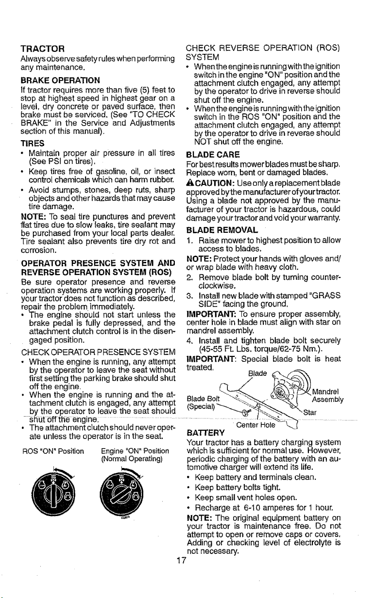
CHECK OPERATOR PRESENCE SYSTEM
CHECK REVERSE OPERATION (ROS)
SYSTEM
* Whenthe engine is running with the ignition
switch in the engine "ON" position and the
attachment clutch engaged, any attempt
by the operator to drive in reverse should
shut offthe engine.
° When the engine is running with the ignition
switch in the ROS ON" position and the
attachment clutch engaged, any attempt
by the operator to drive in reverse should
NOT shut off the engine,
BLADE CARE
For best results mower blades must besharp.
Replace worn, bent or damaged blades,
A CAUTION: Use only a replacement blade
approved bythe manufacturer of your tractor.
Using a blade not approved by the manu-
facturer of your tractor is hazardous, could
damage you r tractor and void your warranty.
BLADE REMOVAL
1. Raise mower to highest position to allow
access to blades.
NOTE: Protect your hands with gloves and/
or wrap blade with heavy cloth.
2. Remove blade bolt by turning counter-
clockwise.
3. install new bladewith stamped "GRASS
SIDE" facing the ground.
IMPORTANT: To ensure proper assembly,
center hole in blade must align with star on
mandrel assembly,
4, install and tighten blade bolt securely
(45-55 Ft. Lbs. torque/62-75 Nm.).
- When the enaine is runnina, any attemot IMPORTANT: Special blade bolt is heat
by the opera{or to leave the se_.t witholJt treated. Blade f..
first setting the parking brake should shut ../ _X\'_
off the engine. (-']- _ l_'x_"_U')) Mandrel
• When the engine is running and the at- B' -e Bolt--"-_ _k_4)'}4 _" -"
tachment clutch is engaged, any attempt ,_a_cial, _,,..._'_'.'_.._ AssemD,y
by the operator to leave the seat should _ ," , -'--_&_"_L_.'_'--_ _\-Star
.....shut 0ffthe engine; ............................................................................_Centel Ho'le_--_-'_. .................................
• The attachmentclutch should never oper- Center Hole k..._I
ate unless the operator is in the seat. BATTERY
Your tractor has a battery charging system
ROS "ON" Position which is sufficient for normal use. However,
Engine "ON" Position
(Normal Operating) periodic charging of the battery with an au-
tomotive charger will extend its life.
° Keep battery and terminals clean.
• Keep battery bolts tight.
• Keep small vent holes open.
• Recharge at 6-10 amperes for 1 hour.
NOTE: The original equipment battery on
your tractor is maintenance free. Do not
attempt to open or remove caps or covers,
Adding or checking level of electrolyte is
not necessary.
17
TOCLEANBATTERYANDTERMINALS
Corrosionanddirtonthebatteryandterminals
cancausethebatteryto"leak"power.
1. DisconnectBLACKbatterycablefirst
thenREDbatterycableandremove
batteryfromtractor.
2. Rinsethebatterywithplainwaterand
dry.
3. Cleanterminalsandbatterycableends
withwirebrushuntilbright.
4. Coatterminalswithgreaseorpetroleum
jelly,
5. Reinstallbattery(See"REPLACING
BATTERY"intheSERVICEANDAD-
JUSTMENTSsectionofthismanual).
TRANSAXLE COOLING
Thetransmission fan and cooling fins should
be kept clean to assure proper cooling.
Do not attempt to clean fan or transmission
while engine is running or while the trans-
mission is hot. To prevent possible damage
to seals, do not use high pressure water or
steam to clean transaxle.
• Inspect cooling fan to be sure fan blades
are intact and clean.
• Inspectcoolingfinsfordirt, grassclippings
and other materials. To prevent damage to
seals, do not use compressed air or high
pressure sprayer to clean cooling fins,
TRANSAXLE PUMP FLUID
The transaxte was sealed at the factory and
fluid maintenance is not required for the life
of the transaxle. Should the transaxle ever
leak or require servicing, contact your near-
est Sears or other qualified service center.
V-BELTS
CheckV-belts for deterioration and wear after
100 hours of operation and replace ff neces-
sary. The belts are not adjustable. Replace
belts if they begin to slip from wear.
ENGINE
LUBRICATION
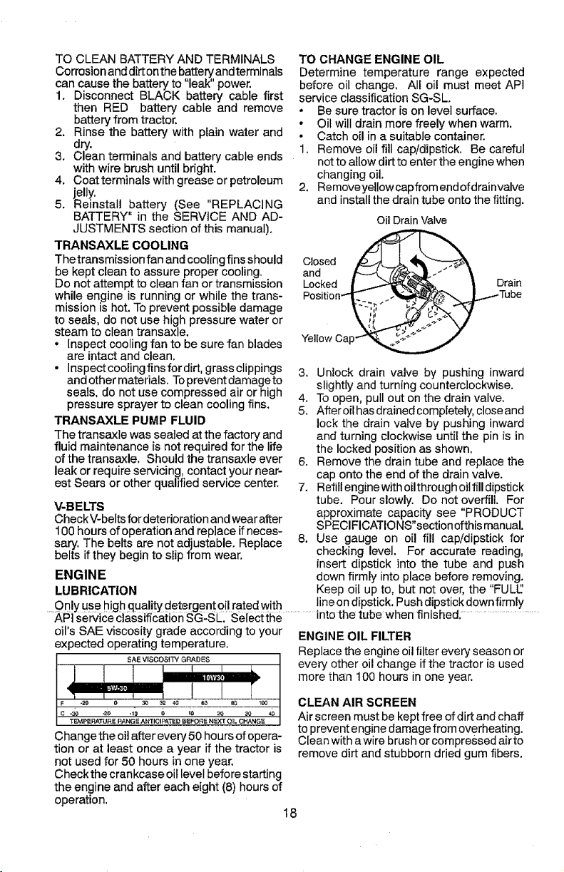
TO CHANGE ENGINE OIL
Determine temperature range expected
before oil change, All oil must meet APt
service classification SG-SL
• Be sure tractor is on level surface,
• Oil will drain more freely when warm.
° Catch oil in a suitable container.
1. Remove oil fill cap/dipstick, Be careful
not to allow dirt to enter the engine when
changing oil.
2. Removeyellow capfrom endofdrainvalve
and install the drain tube onto the fitting.
OilDrain Valve
andClosed ____-_,__L_._
Locked Drain
Position-" Tube
Yellow Cap-
3. Unlock drain valve by pushing inward
slightly and turning counterclockwise.
4, To open, pull out on the drain valve.
5, After oil has drained completely, closeand
lockthe drain valve by pushing inward
and turning clockwise until the pin is in
the locked position as shown,
6. Remove the drain tube and replace the
cap onto the end of the drain valve.
7. Refill enginewith oil through oil fill dipstick
tube. Pour slowly. Do not overfilL For
approximate capacity see "PRODUCT
SPECIFICATIONS"section ofthis manual.
8. Use gauge on oil fill cap/dipstick for
checking level. For accurate reading,
insert dipstick into the tube and push
down firmly into place before removing.
Keep oil up to, but not over, the "FULE'
Only use high quality detergent oil rated with ineon dipstick. Push dipstick down firmly
....APi se-_ice :€ass f ca{ on SG:SI__ Seiect{he ..................rote the tube when finished ........................................
oil's SAE viscosity grade according to your
expected operating temperature.
SAE VISCOSITY GRADES
Change the oi]after every 50 hours of opera-
tion or at least once a year if the tractor is
not used for 50 hours in one year.
Check the crankcase eli level before starting
the engine and after each eight (8) hours of
operation,
ENGINE OIL FILTER
Replace the engine oil filter every season or
every other oil change if the tractor is used
more than t00 hours in one year,
CLEAN AIR SCREEN
Air screen must be kept free of dirt and chaff
to prevent engine damage from overheating.
CIean with a wire brush or compressed airto
remove dirt and stubborn dried gum fibers.
18
AIR FILTER
Your engine will not run properly using a
dirty air filter, Service paper cartridge every
two months or every 25 hours of operation,
whichever occurs first.
Service paper cartridge more often under
dusty conditions.
Replace the paper cartridge annually, or after
every 100 hours of operation.
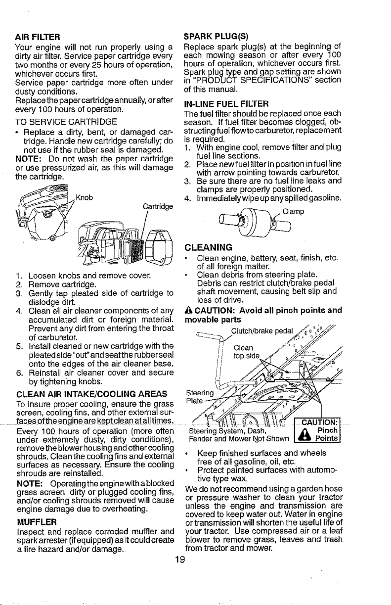
TO SERVICE CARTRIDGE
* Replace a dirty, bent, or damaged car-
tridge. Handle new cartridge carefully; do
not use if the rubber seal is damaged.
NOTE: Do not wash the paper cartridge
or use pressurized air, as this will damage
the cartridge.
__ Knob
Cartridge
SPARK PLUG(S)
Replace spark plug(s) at the beginning of
each mowing season or after every 100
hours of operation, whichever occurs first.
Spark plug type and gap setting are shown
in "PRODUCT SPECIFICATIONS" section
of this manual.
IN-LINE FUEL FILTER
The fuel filter should be replaced once each
season. If fuel filter becomes clogged, ob-
structing fuel flow to carburetor, replacement
is required.
1. With engine cool, remove filter and plug
fuel line sections.
2, Place newfuel filter in position in fuel line
with arrow pointing towards carburetor,
3. Be sure there are no fuel line leaks and
clamps are properly positioned.
4. Immediately wipe upanyspilled gasoline.
amp
1. Loosen knobs and remove cover.
2. Remove cartridge.
3, Gently tap pleated side of cartridge to
dislodge dirt.
4, Clean all air cleaner components of any
accumulated dirt or foreign material.
Prevent any dirt from entering the throat Clutch/brakepedal
of carburetor. ¢z::_z_/
J
5. Install cleaned or new cartridge with the qi Clean /'
pleatedslde"out"andseattherubberseal I)' topside _d/ ,_
onto the edges of the a r c eaner base ! i _k..!_ _/
• iJ
6. Reinstall air cleaner cover and secure i/ //_-
by tightening knobs. __.
CLEAN AIR INTAKE/COOLING AREAS Steer
To insure proper cooling, ensure the grass Plate-----_,jF,)_
screen, cooling fins, and other external sur- /_j[ _/>/'__-_;_=, _//
..............faces of the engineare kept c!ean at a,I!times .............___I_
Every 100 hours of operation (more often SteeringSystem,Dash,
under extremely dusty, dirty conditions), Fenderand Mower_4.otShown
removethe blower housing and other cooling
shrouds. Cleanthe cooling fins and external " Keep finished surfaces and wheels
CLEANING
Clean engine, battery, seat, finish, etc.
of all foreign matter.
• Clean debris from steering plate.
Debris can restrict clutch/brake pedal
shaft movement, causing belt slip and
loss of drive.
& CAUTION: Avoid all pinch points and
movable parts
Y
>
CAUTION: 1 ....
i _ Pinchl
IAI_ PointsJ
surfaces as necessary, Ensure the cooling
shrouds are reinstalled.
NOTE: Operatingthe engine with abtocked
grass screen, dirty or plugged cooling fins,
and/or cooling shrouds removed will cause
engine damage due to overheating.
MUFFLER
Inspect and replace corroded muffler and
spark arrestor (ifequipped) as it could create
a fire hazard and/or damage.
free of all gasoline, oil, etc,
• Protect painted surfaces with automo-
tive type wax.
We do not recommend using a garden hose
or pressure washer to clean your tractor
unless the engine and transmission are
covered to keep water out. Water in engine
or transmission wil! shorten the useful life of
your tractor. Use compressed air or a leaf
blower to remove grass, leaves and trash
from tractor and mower.
19
DECK WASHOUT PORT
Your tractor's deck is equipped with a
washout port on its surface as part of its
deck wash system. It should be utilized af-
ter each use.
1. Drive the tractor to a level, clear spot
on your lawn, near enough to a water
spigot for your garden hose to reach.
IMPORTANT: Make certain the tractor's
discharge chute is directed AWAY from your
house, garage, parked cars, etc. Remove
bagger chute or mulch cover if attached.
2. Ensure the attachment clutch control
is in the "DISENGAGED" position, set
the parking brake, and stop the engine.
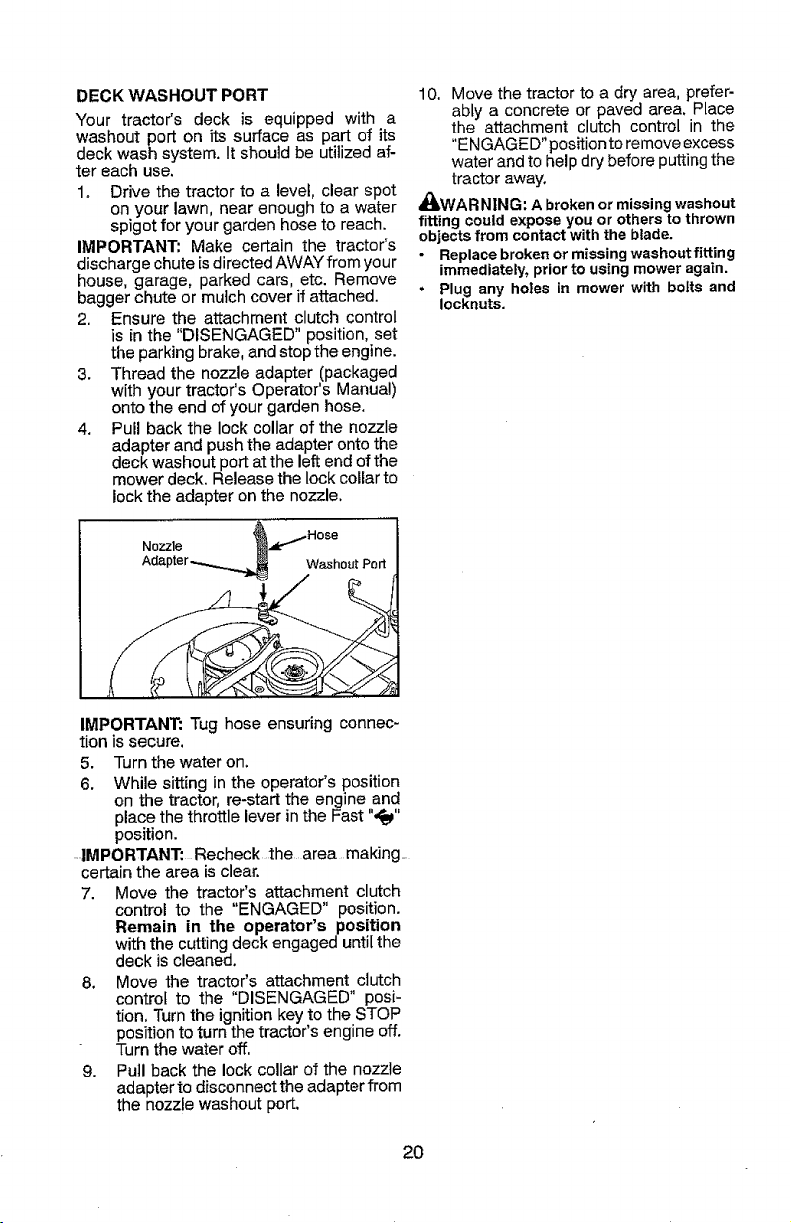
3. Thread the nozzle adapter (packaged
with your tractor's Operator's Manual)
onto the end of your garden hose,
4, Pul! back the lock collar of the nozzle
adapter and push the adapter onto the
deck washout port at the left end of the
mower deck. Release the lock collar to
lock the adapter on the nozzle.
10. Move the tractor to a dry area, prefer-
ably a concrete or paved area. Place
the attachment clutch control in the
"ENGAGED" position to remove excess
water and to help dry before putting the
tractor away.
_WAR N|NG: A broken or missing washout
fitting could expose you or others to thrown
objects from contact with the blade.
• Replace broken or missing washoutfitting
immediately, prior to using mower again.
• Plug any holes in mower with bolts and
Iocknuts.
Nozzle
Washout Port
IMPORTANT: Tug hose ensuring connec-
tion is secure.
5. Turn the water on.
6. While sitting in the operator's position
on the tractor, re-start the engine and
place the throttle lever in the Fast ",_"
position.
IMPORTANT: Recheck the area making_
certain the area is clear.
7. Move the tractor's attachment clutch
control to the "ENGAGED" position.
Remain in the operator's position
withthe cuttingdeck engaged untilthe
deck is cleaned.
8. Move the tractor's attachment clutch
control to the "DISENGAGED" posi-
tion, Turn the ignition key to the STOP
position to turn the tractor's engine off.
Turn the water off,
9. Pull back the lock collar of the nozzle
adapter to disconnect the adapter from
the nozzle washout port.
2O
WARNING: TO AVOID SERIOUS INJURY, BEFORE PERFORMING ANY
SERVICE OR ADJUSTMENTS:
f. Depress brake pedal fully and set parking brake,
2. Place attachment clutch in "DISENGAGED" position.
3, Turn ignition key to "STOP" and remove key.
4. Ensure the blades and all moving parts have completely stopped,
5, Disconnect spark plug wire from spark plug and place wire where it cannot
come in contact with plug,
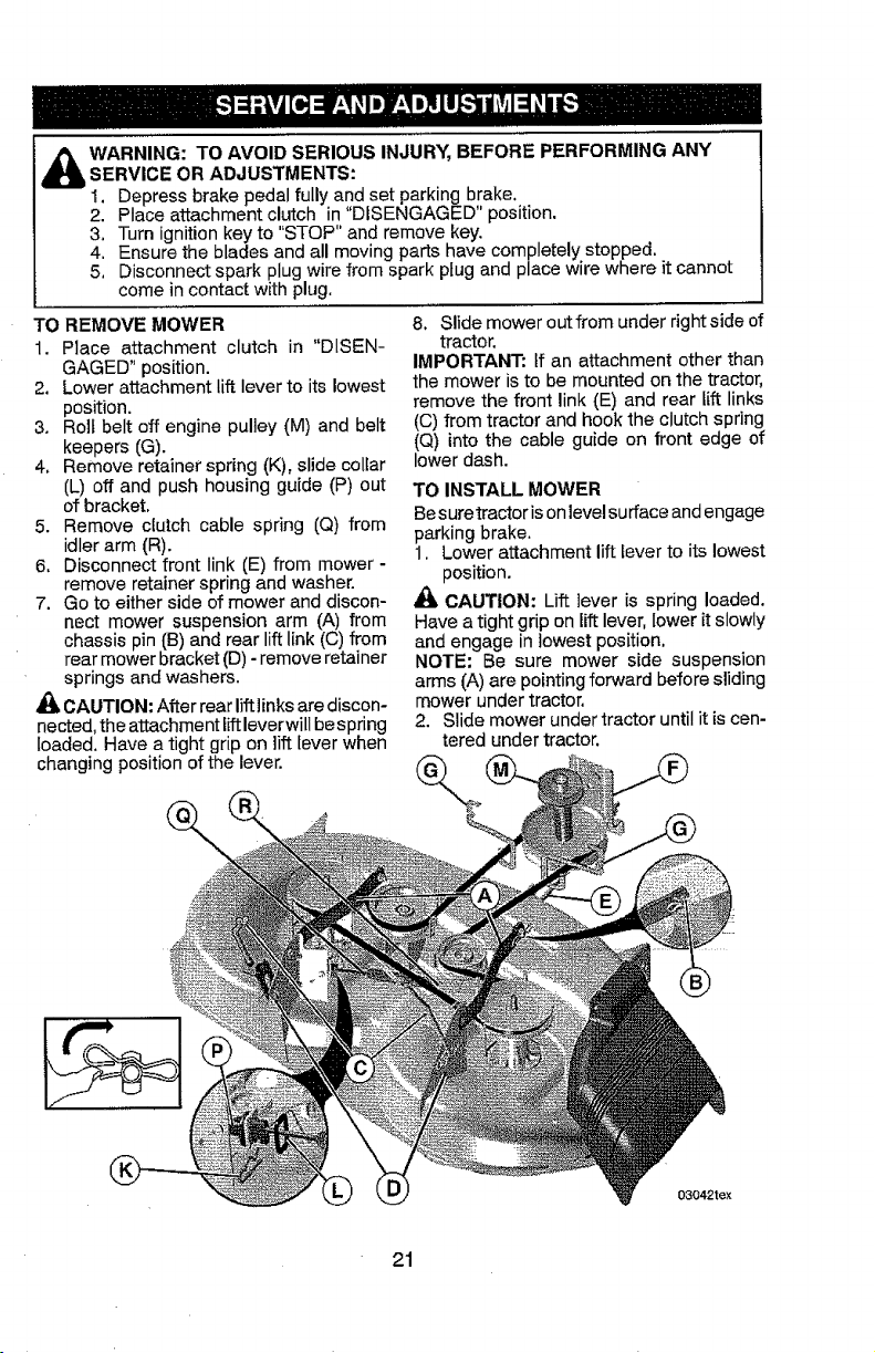
TO REMOVE MOWER
1. Place attachment clutch in "DISEN-
GAGED" position.
2. Lower attachment lift lever to its lowest
position.
3. Roll belt off engine pulley (M) and belt
keepers (G).
4, Remove retainer spring (K), slide collar
(L) off and push housing guide (P) out
of bracket.
5. Remove clutch cable spring (Q) from
idlerarm (R).
6, Disconnect front link (E) from mower -
remove retainer spring and washer.
7. Go to either side of mower and discon-
nect mower suspension arm (A) from
chassis pin (B) and rear lift link (C) from
rear mower bracket (D) - remove retainer
springs and washers,
CAUTION: After rear lift ]inks are discon-
nected, the attachment liftleverwill be spring
loaded, Have a tight grip on lift lever when
changing position of the lever.
8, Slide mower outfrom under right side of
tractor.
IMPORTANT: If an attachment other than
the mower is to be mounted on the tractor,
remove the front link (E) and rear lift links
(C) from tractor and hook the clutch spring
(Q) into the cable guide on front edge of
lower dash.
TO INSTALL MOWER
Be suretractoris on levelsurface and engage
parking brake.
1. Lower attachment lift lever to its lowest
position.
CAUTION: Lift lever is spring loaded.
Have a tight grip on lift lever, lower it slowly
and engage in lowest position,
NOTE: Be sure mower side suspension
arms (A) are pointing forward before sliding
mower under tractor,
2. Slide mower under tractor until it is cen-
tered under tractor,
03042tex
21
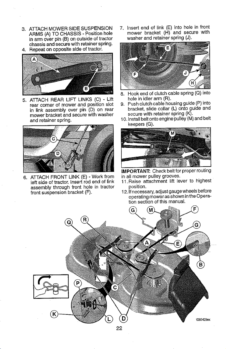
3, ATTACH MOWER SIDE SUSPENSION
ARMS (A) TO CHASSIS - Position hole
in arm over pin (B) on outside of tractor
chassis and secure with retainer spring.
4. Repeat on opposite side of tractor,
7. insert end of link (E) into hole in front
mower bracket (H) and secure with
washer and retainer spring (J).
5_
ATTACH REAR LiFT LINKS (C) - Lift
rear corner of mower and position slot
in link assembly over pin (D) on rear
mower bracket and secure with washer
and retainer spring.
8. Hook end of clutch cable spring (Q) into
hole in idler arm (R).
9. Push clutch cable housing guide (P) into
bracket, slide collar (L) onto guide and
secure with retainer spring (K).
t 0. Install belt onto engine pulley (M) and belt
keepers (G),
6, ATTACH FRONT LINK (E) - Work from
left side of tractor, Insert rod end of link
assembly through front hole in tractor
front suspension bracket (F).
IMPORTANT: Check belt for proper routing
in all mower pulley grooves.
t 1. Raise attachment lift lever to highest
position,
12, If necessary, adjust gauge wheels before
operating mower as shown inthe Opera-
tion section of this manual.
22
03042rex
TO LEVEL MOWER
Ensure tires are properly inflatedto the PSI
shown on tires. If tires are over or under
inflated, it may affect the appearance of your
lawn and lead you to think the mower is not
adjusted properly.
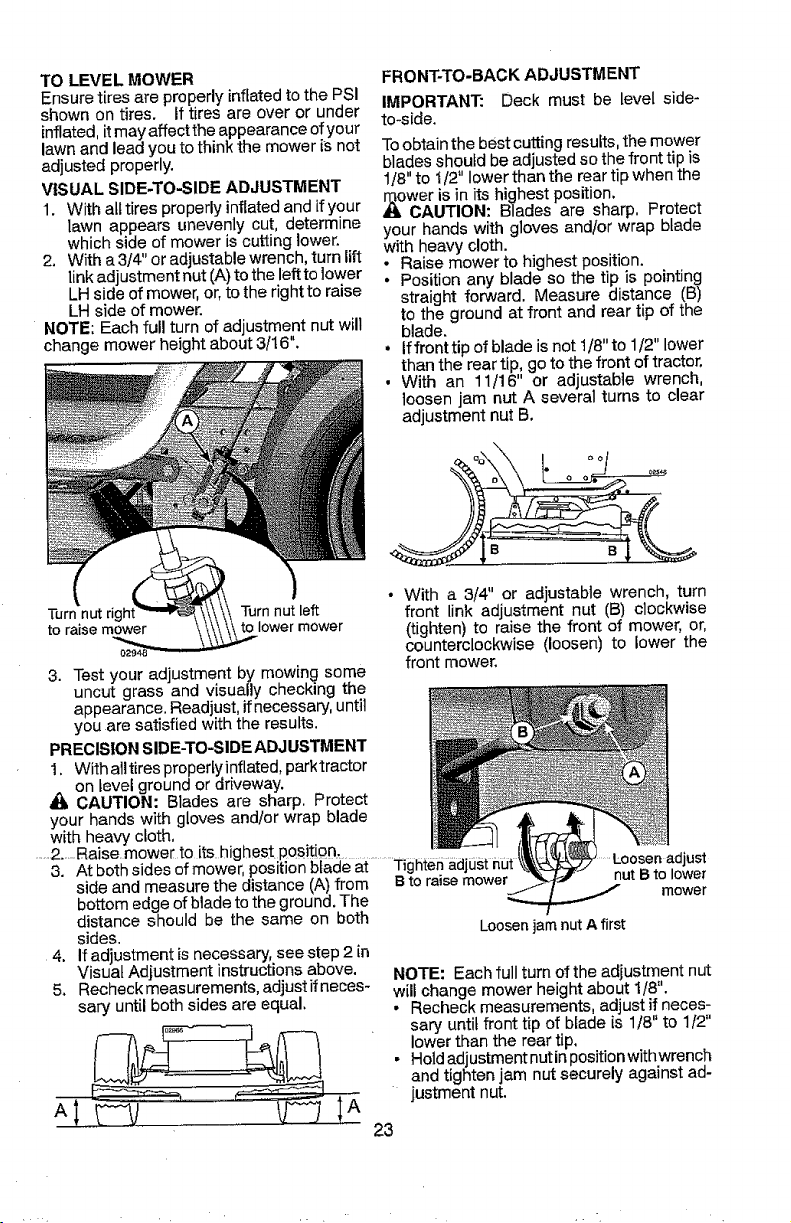
VISUAL SIDE-TO-SIDE ADJUSTMENT
1. With alt tires properly inflatedand if your
lawn appears unevenly cut, determine
which side of mower is cutting lower,
2, With a 3/4" or adjustable wrench, turn lift
link adjustment nut (A) to the left to lower
LH side of mower, or, to the right to raise
LH side of mower.
NOTE: Each full turn of adjustment nut will
change mower height about 3/16.
Turn nut right Turn nut left
to raise mower lower mower
FRONT-TO-BACK ADJUSTMENT
IMPORTANT." Deck must be level side-
to-side.
Toobtain the best cutting results, the mower
blades should be adjusted so the front tip is
1/8" to 1/2" lower than the rear tip when the
_ln_oweris in its highest position.
CAUTION: Blades are sharp. Protect
your hands with gloves and/or wrap blade
with heavy cloth.
• Raise mower to highest position.
• Position any blade so the tip is pointing
straight forward. Measure distance (B)
to the ground at front and rear tip of the
blade.
• If front tip of blade is not 1/8" to 1/2" lower
than the rear tip, go to the front of tractor,
• With an 11/16" or adjustable wrench,
loosen jam nut A several turns to clear
adjustment nut B.
3. Test your adjustment by mowing some
uncut grass and visually checking the
appearance. Readjust,if necessary, until
you are satisfied with the results.
PRECISION SIDE-TO-SIDE ADJ USTMENT
1, With alltires proper[yinflated, parktractor
on level ground or driveway,
CAUTION: Blades are sharp. Protect
your hands with gloves and/or wrap blade
with heavy cloth,
.......2.-.Raise. mower.to its highest,posjtiQn...........................
3. At both sides of mower, positionblade at Tighten_c
side and measure the distance (A) from B to raisemower
bottom edge of blade to the ground. The
distance should be the same on both
sides.
4. if adjustment is necessary, see step 2 in
Visual Adjustment instructions above.
5. Recheckmeasurements, adjust ifneces-
sary until both sides are equal.
• With a 3/4" or adiustabie wrench, turn
front link adjustment nut (B) clockwise
(tighten)to raise the front of mower, or,
counterclockwise (loosen) to lower the
front mower.
....Loosen adjust
nut B to lower
mower
Loosen jam nut A first
NOTE: Each full turn of the adjustment nut
will change mower height about 1/8".
Recheck measurements, adjust if neces-
sary until front tip of blade is 1/8" to 1/2"
lower than the rear tip,
• Hold adjustment nutin position with wrench
and tighten jam nut securely against ad-
justment nut.
23
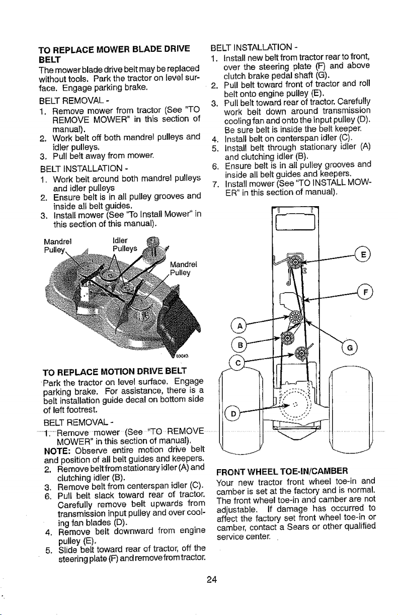
TO REPLACE MOWER BLADE DRIVE
BELT
The mower blade drive bett may be replaced
without tools, Park the tractor on level sur-
face, Engage parking brake.
BELT REMOVAL -
1. Remove mower from tractor (See "TO
REMOVE MOWER" in this section of
manual).
2. Work belt off both mandrel pulleys and
idler pulleys,
3. Pull belt away from mower.
BELT INSTALLATION -
1. Work belt around both mandrel pulleys
and idler pulleys
2. Ensure belt is in all pulley grooves and
inside all belt guides,
& Install mower (See "To Install Mower" in
this section of this manua0.
Mandrel Idler
Pulleys
Mandrel
BELT INSTALLATION -
1, installnew belt from tractorrear to front,
over the steering plate (F) and above
clutch brake pedal shaft (G).
2. Pull belt toward front of tractor and roll
belt onto engine pulley (E).
3, Pull belt toward rear of tractor, Carefully
work belt down around transmission
cooling fan and onto the input pulley (D),
Be sure belt is inside the belt keeper.
4. Install belt on centerspan idler (C).
5. tnstali belt through stationary idler (A)
and clutching idler (B),
6, Ensure belt is in all pulley grooves and
inside all belt guides and keepers,
7. Install mower (See "TO INSTALL MOW-
ER" in this section of manual).
TO REPLACE MOTION DRIVE BELT
Park the tractor on level surface. Engage
parking brake. For assistance, there is a
belt installation guide decal on bottom side
of left footrest.
BELT REMOVAL -
......1,-'Remove mower (See. _'TO-REMOVE .........
MOWER" in this section of manual).
NOTE: Observe entire motion drive belt
and position of all belt guides and keepers,
2. Remove beltfrom statJonaryidler (A)and
clutching idler (B).
3. Remove belt from centerspan idler (C).
6. Pull belt slack toward rear of tractor,
Carefully remove belt upwards from
transmission input pulley and over cool-
ing fan blades (D).
4, Remove belt downward from engine
pulley (E),
5. Slide belt toward rear of tractor, off the
steering plate (F)and remove from tractor.
FRONT WHEEL TOE-IN!CAMBER
"your new tractor front wheel toe-in and
camber is set at the factory and is normal.
The front wheel toe4n and camber are not
adjustable. If damage has occurred to
affect the factory set front wheel toe-in or
camber, contact a Sears or other qualified
service center.
24
TO CHECK BRAKE
If tractor requires more than five (5) feet to
stop at highest speed in highest gear on a
level, dry concrete or paved surface, then
brake must be serviced.
You may also check brake by:
1. Park tractor on a level, dry concrete or
paved surface, depress brake pedal all
the way down and engage parking brake.
2. Disengage transmission by placing
freewheel control in "transmission dis-
engaged" position. Pullfreewheel control
out and into the slot and release so it is
held in the disengaged position.
The rear wheels must lock and skid when
you try to manually push the tractor forward.
If the rear wheels rotate, then the brake
needs to be serviced. Contact a Sears or
other qualified service center,
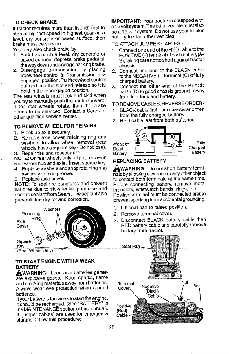
TO REMOVE WHEEL FOR REPAIRS
t. Block up axle securely.
2. Remove axle cover, retaining ring and
washers to allow wheel removal (rear
wheels have a square key- Do not lose).
3. Repair tire and reassemble.
NOTE: On rearwheels only: align grooves in
rear wheel hub and axle, Insertsquare key.
4. Reptacewashers and snap retaining ring
securely in axle groove.
5. Replace axle cover.
NOTE: To seal tire punctures and prevent
flat tires due to slow leaks, purchase and
use tire sealant from Sears. Tire sealant also
prevents tire dry rot and corrosion,
Washers
Retaining
IMPORTANT: Your tractor is equipped with
a 12vottsystem. The othervehicte must also
be a 12volt system. Do not use your tractor
battery to start other vehicles.
TO ATTACH JUMPER CABLES -
1. Connect one end ofthe RED cableto the
POSITIVE (+) terminal of each battery(A-
B),taking care notto short against tractor
chassis.
2. Connect one end of the BLACK cable
to the NEGATIVE (-)terminal (C) of fu!ly
charged battery.
3. Connect the other end of the BLACK
cable (D) to good chassis ground, away
from fuel tank and battery.
TO REMOVE CABLES, REVERSE ORDER-
1, BLACK cable first from chassis and then
from the fully charged battery.
2. RED cable last from both batteries.
Weak or Fully
Dead Charged
Battery Battery
REPLACING BATTERY
n_asWbARNING:Do not short battery termi-
yallowing a wrenchor any other object
to contact both terminals at the same time.
Before connecting battery, remove metal
bracelets, wristwatch bands, rings, etc.
Positive terminal must be connected first to
preventsparking from accidental grounding.
1. Lift seat pan to raised position.
2. Remove terminal cover.
3. Disconnect BLACK battery cable then
RED battery cable and carefully remove
battery from tractor.
(Rear Wheel Only)
TO START ENGINE WITH A WEAK
BATTERY
,_LWARNING: Lead-acid batteries gener-
ate explosive gases. Keep sparks, flame
and smoking materials away from batteries.
Always wear eye protection when around
batteries.
If your battery is too weak to star[the engine,
it should be recharged. (See "BATTERY" in
the MAINTENANCE section ofthis manual).
If "jumper cables" are used for emergency
starting, follow this procedure:
25
.Seat J
Terminal
Cover..N Negative
(Black)
Positive
(Red)
Nut
Bolt
, .. .
4. Insta!l new battery with terminals insame
position as old battery.
5. Reinstall terminal cover.
6. First connect RED battery cable to posi-
tive (+) battery terminal with bolt and nut
as shown. Tighten securely.
7. Connect BLACKgrounding cabieto nega-
tive (-) battery terminal with remaining
bolt and nut. Tighten securely
8. Lower seat pan.
TO REPLACE HEADLIGHT BULB
1. Raise hood.
2. Remove bulb holderfrom the hole inthe
backside of the grill.
3. Repiace bulb in holder and install bulb
holder securely back intothe hole in the
backside of the grill.
4. Close hood.
INTERLOCKS AND RELAYS
Loose or damaged wiring may cause your
tractor to run poorly, stop running, or prevent
it from starting.
• Check wiring.
TO REPLACE FUSE
Replace with 30 amp automotive-type plug-
in fuse. The fuse holder is located behind
the dash.
TO REMOVE HOOD AND GRILL AS-
SEMBLY
t. Raise hood.
2. Unsnap headlight wire connector,
3. Stand in front of tractor. Grasp hood at
sides, tilt toward engine and lift off of
tractor.
4. When replacing hood, be sure to recon-
nect the headlight wire connector.
TRANSMISSION REMOVAL/
REPLACEMENT
Should your transmission require removalfor
service or replacement, it should be purged
after reinstallation and before operating the
tractor. See "PURGE TRANSMISSION" in
the Operation section of this manual.
ENGINE
TO ADJUST THROTTLE CONTROL
CABLE
The throttle control has been preset at
the factory and adjustment should not be
necessary Check adjustment as described
below before loosening cable. If adjustment
is necessary, see engine manual.
TO ADJUST CHOKE CONTROL
The choke control has been preset at the
factory and adjustment should not be neces-
sary, If adjustment is necessary, see engine
manual.
TO ADJUST CARBURETOR
Your carburetor hasbeen preset atthe factory
and adjustment should not be necessary,
However, minor adjustment may be required
to compensate for differences in fuel, tem-
perature, altitude or load. If the engine does
need adjustment, see engine manual.
HeadlightWire
Connector
26
Immediately prepare your tractor for Storage
at the end of the season or if the tractor will
be used for 30 days or more.
RNING: Never store the tractor with
gasoline in the tank inside a building where
fumes may reach an open flame or spark.
Allow the engine to coot before storing in
any enclosure,
TRACTOR
When tractor is to be stored for a period
of time, clean it thoroughly, remove all dirt,
grease, leaves, etc. Store inaclean, dry area.
1. Clean entiretractor (See "CLEANING" in
the Maintenance section of this manual).
2. Inspect and replace belts, if necessary
(See belt replacement instructions in the
Service and Adjustments section of this
manual).
3. Lubricate as shown in the Maintenance
section of this manual.
4. Be sure that al! nuts, bolts and screws
are securely fastened. Inspect moving
parts for damage, breakage and wear.
Replace if necessary.
5. Touch up all rusted or chipped paint
surfaces; sand lightly before painting.
BATTERY
• Fully charge the battery for storage.
- After a period of time in storage, battery
may require recharging.
° To help prevent corrosion and power
leakage during long pedods of storage,
battery cables should be disconnected
and battery cleaned thoroughly (see "TO
CLEAN BATTERY AND TERMINALS" in
the Maintenance section of this manual).
, After cleaning, leave cables disconnected
and place cables where they can notcome
• Empty the fuel tank by startingthe engine
and letting it run until the fuel lines and
carburetor are empty.
• Never use engine or carburetor cleaner
products in the fuel tank or permanent
damage may occur.
. Use fresh fuel next season.
NOTE: Fuel stabilizer is an acceptable al-
ternative in minimizing the formation of fuel
gum deposits during storage. Add stabilizer
to gasoline infuel tank or storage container.
Always followthe mix ratio found on stabilizer
container, Run engine at least 10 minutes
after adding stabilizer to al[owthe stabilizerto
reach the carburetor. Do not empty the gas
tank and carburetor if using fuel stabilizer.
ENGINE OIL
Drain oil (with engine warm) and replace
with clean engine oil. (See "ENGINE" in the
Maintenance section of this manual).
CYMNDER(S)
1. Remove spark plug(s).
2. Pour one ounce of oil through spark plug
hole(s) into cylinder(s).
3. Tbrn ignition key to start position for a
few seconds to distribute oil,
4. Replace with new spark plug(s).
OTHER
• Do not store gasoline from one season to
another,
• Replace yourgasoline can ifyour can starts
to rust. Rust and/or dirt in your gasoline
will cause problems.
• If possible, store your tractor indoors and
cover it to give protection from dust and
dirt.
• Cover your tractor with a suitable protec-
tive cover that does not retain moisture.
n contant with hatt_, term;-al - Do not use plastic, Plasticcannot breathe
: I:f' ba'_ery' is re'move_Ydfrom {r_act0rfOr .............wh,ch a ows condensation to form and w,l)........
storage, do not store battery directly on cause your tractor to rust.
concrete or damp surfaces. IMPORTANT: Never cover tractor while
engine and exhaust areas are still warm,
ENGINE
FUEL SYSTEM
IMPORTANT: It is important to prevent
gum deposits from forming in essential fuel
system parts such as carburetor, fuel hose,
or tankduring storage. Also, alcohol blended
fuels (called gasohol or using ethanol or
methanol) can attract moisture which leads
to separation and formation of acids during
storage. Acidic gas can damage the fuel
system of an engine while in storage.
27
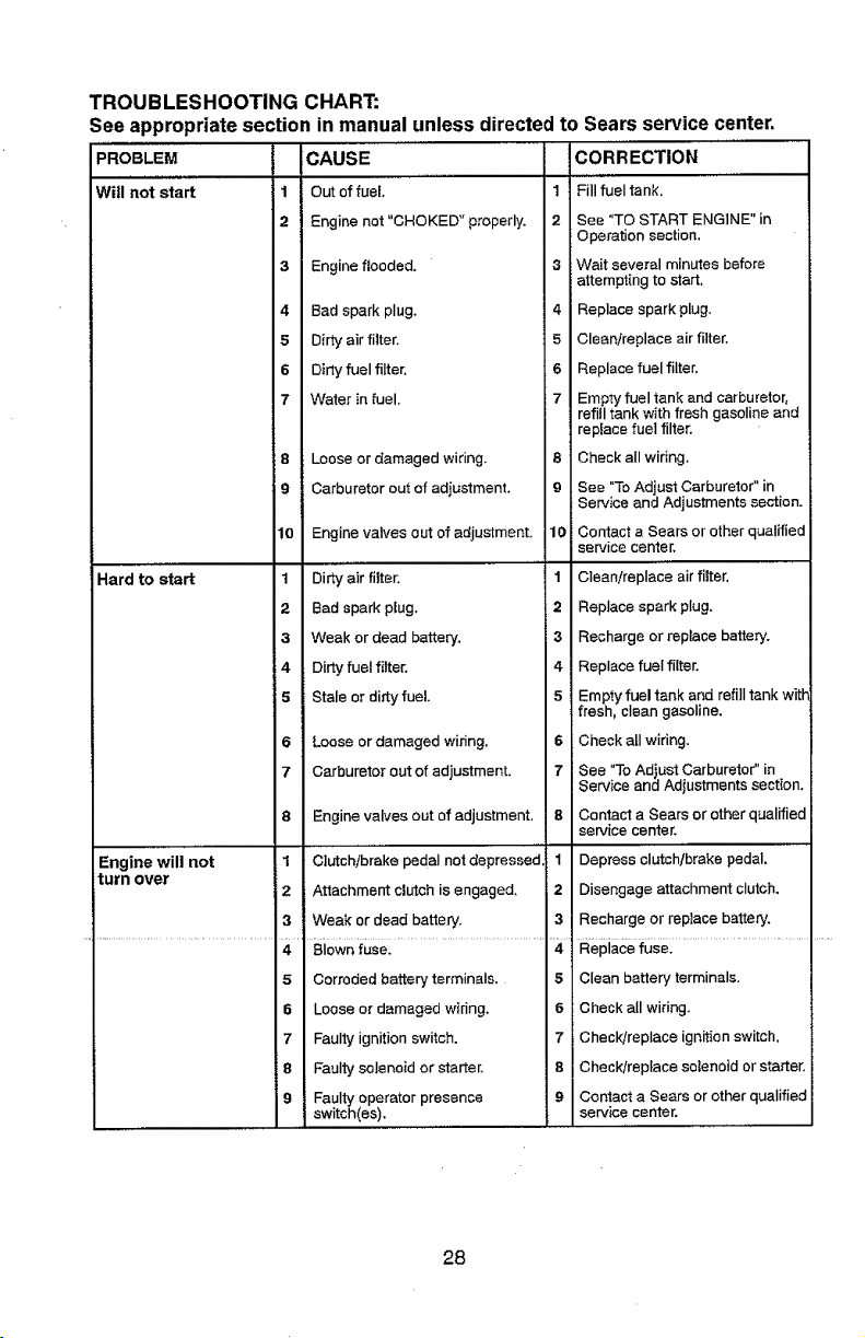
TROUBLESHOOTING CHART:
See appropriate section in manual unless directed to Sears service center.
PROBLEM CAUSE CORn ECTiON
Will not start J1 Out of fuel. 1 Fill fuel tank.
2 Engine not "CHOKED" properly. 2
3 Engine ftooded.
4 Bad spark plug.
5 Dirty air filter.
6 Dirty fuel filter.
7 Water in fuel.
Loose or damaged wiring.
Carburetor out of adjustment,
Hard to start
8
9
lO
1
2
3
4
5
6
7
Engine will not 1
turn over
2
3
4
5
6
7
8
9
Engine valves out of adjustment.
Dirty air filter.
Bad spark plug.
Weak or dead battery,
Dirty fuel filter,
Stale or dirty fuel.
Loose or damaged wiring.
Carburetor out of adjustment.
Engine valves out of adjustment.
Clutch/brake pedal not depressed
Attachment clutch is engaged,
Weak or dead battery.
Blown fuse,
Corroded battery terminals.
Loose or damaged wiring.
Faulty ignition switch.
Faulty solenoid or starter,
Faulty operator presence
switch(as),
See "TO START ENGINE" in
Operation section.
3 Wait several minutes before
attempting to start.
4 Replace spark plug.
5 Clean/replace air filter.
6 Replace fuel filter.
7 Empty fuel tank and carburetor,
refill tank with fresh gasoline and
replace fuel filter.
8 Check allwiring.
9
10
1
2
13
4
5
6
7
See "To Adjust Carburetor" in
Service and Adjustments section.
Contact a Sears or other qualified
I service center.
Clean/replace air filter.
Replace spark plug.
Recharge or replace battery.
Replace fuel filter.
Empty fuel tank and refill tank witt
fresh, clean gasoline.
Check all wiring.
See "To Adjust Carburetor" in
Service and Adjustments section.
Contact a Sears or other qualified
service center.
Depress clutch/brake pedal.
Disengage attachment clutch.
Recharge or replace battery.
Replace fuse.
Clean battery terminals.
Check all wiring.
Check!replace ignition switch.
Check!replace solenoid or starter.
Contact a Sears or other qualified
service center.
1
2
3
5
6
7
8
9
28
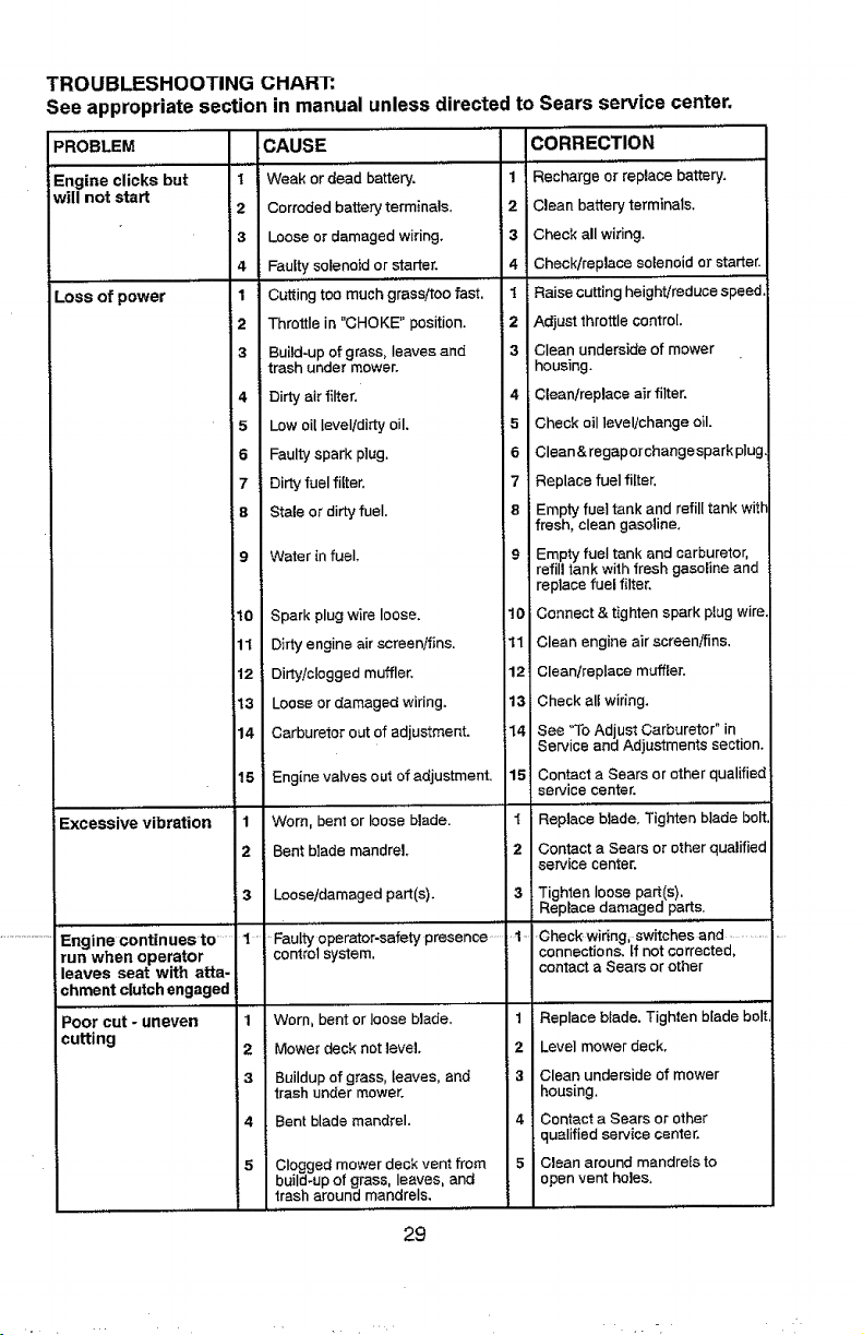
TROUBLESHOOTING CHART:
See appropriate section in manual unless directed to Sears service center.
PROBLEM
Engine clicks but
will not start
6 Faulty spark plug.
7 Dirty fuel filter.
8 Stale or dirty fuel.
CAUSE
Weak or dead battery, 1
Corroded battery terminals, 2
Loose or damaged wiring. 3
Faulty solenoid or starter. 4
Cutting too much grass/too fast. 1
Throttle in "CHOKE" position. 2
Build-up of grass, leaves and 3
trash under mower.
Dirty air filter. 4
Low oil IeveIidirty oil. 5
6
7
8
1
2
3
4
1
2
3
4
5
Loss of power
Engine continuesto .......1 -
run when operator
leaves seat with atta-
chment clutch engaged
Poor cut - uneven 1
cutting 2
9 Water in fuel,
10 Spark plug wire loose.
11 Dirty engine air screen!fins.
12 Dirty/clogged muffler,
13 Loose or damaged wiring.
14 Carburetor out of adjustment.
15 Engine valves out of adjustment.
1 Worn. bent or loose blade.
2 Bent blade mandrel,
4
5
Loose/damaged part(s).
Faulty operator-safety presence .....
control system.
Worn. bent or loose blade.
Mower deck not level,
Buildup of grass, leaves, and
trash under mower,
Bent blade mandrel.
Clogged mower deck vent from
build-up of grass, leaves, and
trash around mandrels,
10
11
12
13
14
15
2
3
CORRECTION
Recharge or replace battery,
Clean battery terminals.
Check all wiring.
Check/replace solenoid or starter.
Raise cutting height/reduce speed
Adjust throttle control.
Clean underside of mower
housing,
i Clean/replace air filter,
Check oil level/change oil.
Clean& regaporchangespark plug.
Replace fueI filter.
Empty fuel tank and refill tank with
fresh, clean gasoline.
Empty fuel tank and carburetor,
refill tank with fresh gasoline and
replace fuel filter.
Connect & tighten spark plug wire.
Clean engine air screen/fins,
Clean/replace muffler.
Check all wiring,
See "To Adjust Carburetor" in
Service and Adjustments section.
Contact a Sears or ether qualified
service center.
Replace blade. Tighten blade bolt
Contact a Sears or other qualified
service center,
Tighten loose part(s).
Rep ace damaged parts.
Check wir_ng_switches and .............
connections, tf not corrected.
contact a Sears or other
1 Replace blade, Tighten blade bolt
2 Level mower deck.
3 Clean underside of mower
housing.
4 Contact a Sears or other
qualified service center.
5 Clean around mandrels to
open vent holes.
29
,. =
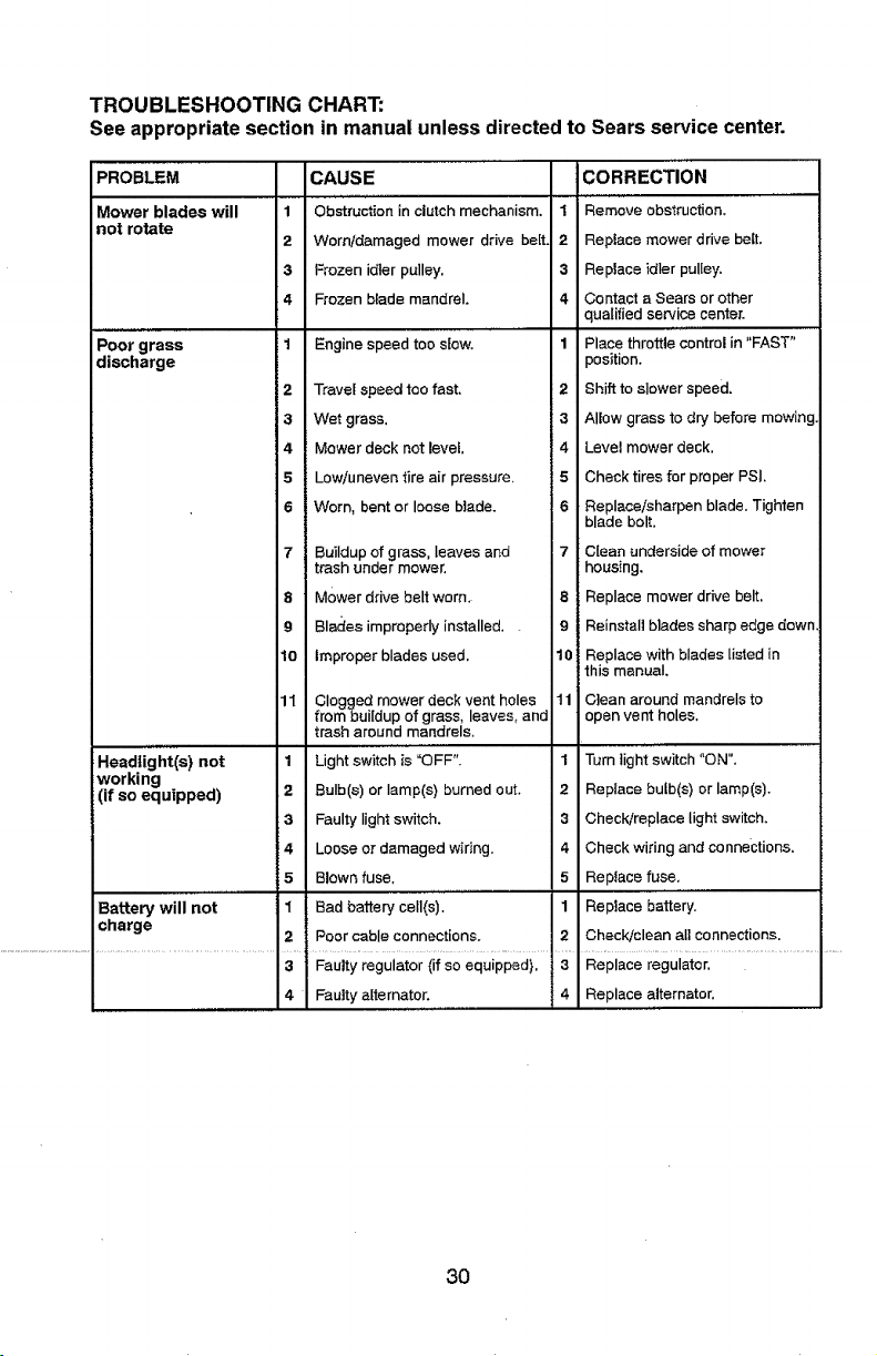
TROUBLESHOOTING CHART:
See appropriate section in manual unless directedto Sears service center.
PROBLEM
Mower blades will
not rotate
Poor grass
discharge
CAUSE CORRECTION
1 Obstruction in clutch mechanism, 1 Remove obstruction,
2 Worn/damaged mower drive be[t. 2 Replace mower drive belt.
3 Frozen idler pulley. 3 Replace idler pulley,
4 Frozen blade mandrel, 4 Contact a Sears or other
qualified service center.
i 1 Engine speed too slow, 1 Place throttle control in "FAST"
position,
i 2 Travel speed too fast, 2 Shift to slower speed,
3 Wet grass. 3 Allow grass to dry before mowing,
4 Mower deck not level. 4 Level mower deck.
5 Low/uneven tire air pressure, 5 Check tires for proper PSI,
6 Worn, bent or loose blade. 6 Replace/sharpen blade. Tighien
blade bolt.
7 Buildup of grass, leaves and 7 C{ean underside of mower
trash under mower, housing.
8 Mower drive belt worn. 8 Replace mower drive belt.
9 Blades impreperly installed.. 9 Reinstall blades sharp edge down.
10 Improper blades used. 10 Replace with blades listed in
this manual,
11 Clogged mower deck vent holes 11 CIean around mandrels to
from buildup of grass, leaves, and open vent holes.
trash around mandrels.
,.,,,,,,..............
Headlight(s) not 1 Light switch is "OFF". I Turn tight switch "ON".
working
(if so equipped) 2 Bulb(s) or lamp(s) burned ouL 2 Reptace bulb(s) or lamp(s).
3 Faulty light switch, 3 Check/replace light switch,
4 Loose or damaged wiring, 4 Check wiring and connections,
5 Blown fuse, 5 Replace fuse.
Battery will not I Bad battery ceil(s). 1 Replace battery.
charge
2 Poor cabIe connections, 2 Check/clean all connections.
3 Faulty regulator (if so equipped). 3 Replace regulator.
4 Fautty alternator, 4 Replace alternator.
3O

TROUBLESHOOTING CHART:
See appropriate section in manual unless directedto Sears service center.
PROBLEM ICAUSE CORRECTION
Loss of drive 1 Freewheel control in 1 Place freewheel control in
"DISENGAGED" position. "ENGAGED" position.
2 Debris on steering plate (if 2 See "CLEANING" in the
equipped), maintenance section.
3 Motion drive beJt worn, damaged, 3 Replace motion drive belt.
or broken.
4 i Air trapped in transmission during 4 Purge transmission.
I
shipment or servicing.
i 5 Axle key missing. 5
Engine "backfires" 1 Engine throttle control not eel 1
when turning between half and full speed (fast
engine "OFF" position before stopping engine.
......... , ,_ ,,.,,.....................
Engine dies when 1 Reverse operation system (ROS) 1
tractor is snirted is not "ON" while mower or other
into reverse attachment is engaged,
Insta8 axle key at rear wheel. See
"TO REMOVE WHEEL" inthe
Service and Adjustments section.
,,,,,L
Move throttle control between
half and ful! speed (!ast) position
i before stopping engine.
Turn ignition key to ROS "ON"
position. See Operation section.
NEED MORE HELP?
i You'tl find the answer a_d more on managemyhome.com - for free! _!
i " Find this and a[[ your other product manua[s online.
• Get answers from our team of home experts.
• . Get a personalized maintenance pl.an for your home.
i " Find information and tools to he|p with home projects. _
manage home
i brought to yon l_y Sea_s
31
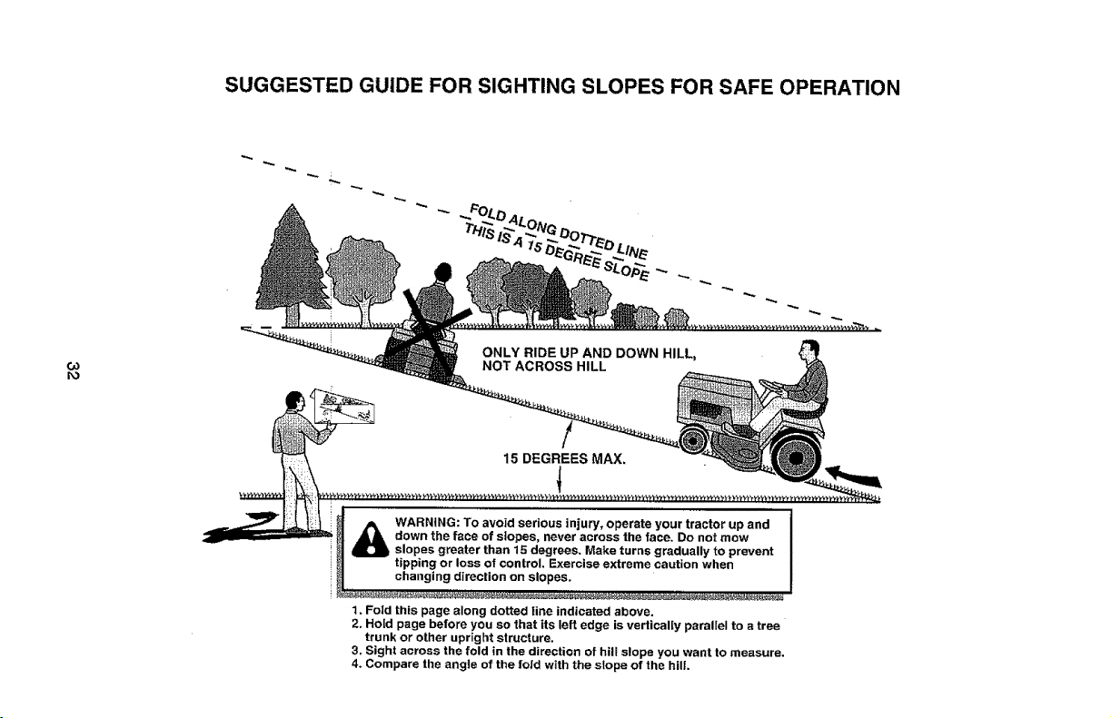
SUGGESTED GUIDE FOR SIGHTING SLOPES FOR SAFE OPERATION
G3
ro
ONLY RIDE UP AND DOWN HILL,
NOT ACROSS HILL
15 DEGREES MAX,
WARNING: To avoid serious injury, operate your tractor up and
down the face of slopes, never across the face. Do not mow
slopes greater than 15 degrees. Make turns gradually to prevent
tipping or loss of control. Exercise extreme caution when
changing direction on slopes.
1. Foid this page along dotted line indicated above.
2. Hold page before you so that its left edge is vertically parallel to a tree
trunk or other upright structure.
3r Sight across the fold in the direction of hill slope you want to measure.
4_ Compare the angle of the fold with the slope of the hill
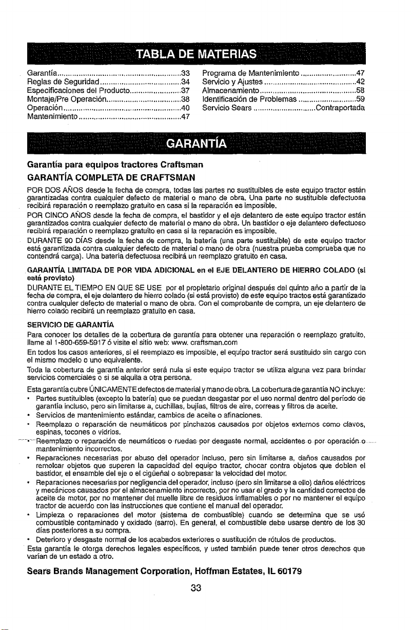
Garantia .......................................................... 33
Reglas de Seguridad ...................................... 34
Especificaciones del Producto ........................ 37
MontajeiPre Operaci6n ................................... 38
Operaci6n ....................................................... 40
Mantenimiento ................................................ 47
Prograrna de Mantenimiento .......................... 47
Servicio y Ajustes ........................................... 42
Almacenamiento ............................................. 58
Identiflcaci6n de Problemas ........................... 59
Servicio Sears ............................. Contraportada
Garantia para equipos tractores Craftsman
GARANTJA COMPLETA DE CRAFTSMAN
PeR DOS Af'4OS desde ]a fecha de compra, todas [as partes no sustituibtes de este equipo tractor est_n
garantizadas contra cualquier defecto de material o mane de obra. Una parte no sustituible defectuosa
recibir& reparaci6n o reemp]azo gratuite en case si la reparaci6n es imposible.
PeR CINCO ANOS desde Ia fecha de compra, el bastidor y el eje delantero de este equipo tractor estan
garantizados centre cualquier defecto de material o mane de obra. Un bastidor o eje delantero defectuoso
recibir_ reparaci6n o reemplazo gratuito en case si Ia reparacion es imposible.
DURANTE 90 DJ'AS desde la fecha de compra, la bateria (una parte sustituible) de este equipo tractor
est,. garantizada centre cualquier defecto de material o mane de obra (nuestra prueba comprueba que no
contendr_ carga). Una bateria defectuosa recibir_, un reemplazo gratulto en case.
GARANTiA LIMITADA DE PeR VIDA ADICIONAL en el EJE DELANTERO DE HIIERRO COLADO (si
estb provisto)
DURANTE EL TIEMPO EN QUE SE USE per el propietario original despu6s del quinto afro a partir de ia
fecha de compra, el eje delantero de hierro colado (si est_ provisto) de este equipo tractos est& garantizado
centre cualquier defecto de material o mane de obra, Con el comprobante de compra, un eje delantero de
hierro colado recibir_ un reemplazo gratuito en case.
SERVIClO DE GARANTJA
Pare conocer los detalles de la cobertura de garantia pare obtener una reparaci6n c reemp_azo gratuito,
llame al 1-800-659-5917 6 visite el sitio web: www. craftsman.cam
En redes los cases anteriores, si et reemplazo es imposible, el equipo tractor ser_ sustituido sin cargo con
el mismo modefo o uno equivalente.
Toda la cobertura de garantia anterior ser& nula si este equipo tractor se utiiiza alguna vez pare brindar
servicios comerciales o si se alquila a otra persona.
Esta garantia cubre 0N]CAMENTE defectos de mate rial y mane de obra. La cobertura de garantia NO incluye:
• Partes sustituibles (excepto la bater[a) que se puedan desgastar per eI use normal dentro del periodo de
garantJa incluso, pete sin limitarse a, cuchillas, bujias, filtros de aire, correas y filtros de aceite.
• Servicios de mantenimiento est&ndar, cambios de aceite o afinaciones.
° Reemplazo o reparaci6n de neum_ticos per pinchazos causados per objetos extemos come cfavos,
espinas, tecones o vidrios.
.......,_'_Reemplazo o reparaci6n-de neumAticos o ruedas per desgaste norma]_ aceidentes.o per operaci6n o ......
mantenimiento incorrectos.
• Reparaciones necesarias per abuse del operador incluso, pare sin limitarse a, rases causados per
remolcar objetos qua superen la capacidad deI equipo tractor, chocar contra objetes qua doblen el
bastidor, el ensamble det eje o el cig_e_aI o sobrepasar la velocidad del motor.
• Reparaciones necesarias per negfigencia del operador, incluso (pare sin Iimitarse a ella) da_.os eI6ctricos
y mec&nicos causados per el almacenamiento incorrecto, per no usar el grade y Ia canfidad correctos de
aceite de motor, per no mantener dot muelle Iibre de residues infiamables o per no mantener el equipo
tractor de acuerdo con las instrucciones qua contiene et manual deI operador.
• Limpieza o reparaciones de1 motor (sistema de combustible) cuando se determina que se us6
combustible contaminado y oxidado (sarro). En general, el combustible debe usarse dentro de los 30
dJas posteriores a su compra.
° Deterioro y desgaste normal de los acabados extedores o sustituci6n de r6tulos de productos.
Esta garantJa le oterga derechos legales especfficos, y usted tambi6n puede tener otros detaches que
varian de un estado a otto.
Sears Brands Management Corporation, Hoffman Estates, IL 60179
33
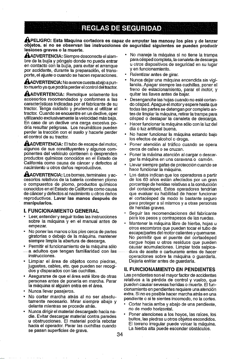
_PELIGRO: Esta Maquina cortadora es capaz de amputar las manosy los pies y de lanzar
objetos, si no se observan las instrucciones de seguridad siguientes se pueden producir
lesiones graves o la muerte.
_DVERTENCIA: Siempre desconecteel alam-
bre de la buj(a y p6ngalo donde no pueda entrar
en contacto con la buj[a, para evitar el arranque
per accidente, durante la preparaci6n, el trans-
porte, el ajuste o cuando se hacen reparaciones.
_I_DVERTENCIA: Noavance cuestaabajo a pun-
tomuerto ya quepodriapettierel cor_roldeltractor.
_I_DVERTENCIA: Remolque solamente los
accesorios recomendados y conformes a las
caracteristicas indicadas perel fabricante de su
tractor. Tenga cuidado y prudencia al utilizar el
tractor. Cuando se encuentre en un declive, oper
utilizandoexclusivamentelavelocidad m_.sbaja.
En case de un declive una carga excesiva po-
dr[a resultar peligrosa. Los neum_.ticos pueden
perder la tracci6n con el suelo y hacerle perder
el control de sutractor.
_DVERTENCIA: El tube deescape deI motor,
algunos de sus constituyentes y algunos com-
ponentes del vehiculo contienen o desprenden
productos quimicos conocidos en el Estado de
California come eausa de c&ncer y defectos af
nacimiento u otros dafios reproductivos.
_I_ADVERTENCIA: Losbornes, terminalesyac-
cesorios relatives de la bateria contienen plomo
o compuestes de plomo, productos quimicos
conocidos en el Estado de California come causa
de c,_ncer y defectos al nacimiento u otros dafios
reproductivos. Lavar las manes despu@s de
manipularlos.
!, FUNCIONAMIENTO GENERAL
• Leer,entender y seguir todas Ias instrucciones
sobre Ia m&quina y en el manual antes de
empezar.
• No porter las manes o los pies cerca de partes
giratorias o debajo de ]a m&quina, rnantener
siempre Iimpia Ia abertura de descarga.
• Permitir el funcionamiento de la m&quina s61o
• No maneje fa m&quina si no tiene la trarnpa
para c@spedcomp]eta, la canaleta dedescarga
u otros dispositivos de seguridad en su lugar
yen foncionamiento.
• RaIentizar antes de girar.
• Nunca dejar una m_quina encendida sin vigk
lancia. Apagar siempre las cuchil[as, poner el
freno de estacionamiento, parar el motor, y
quitar Ias [laves antes de bajar.
• Desenganche Ias hojas cuando noest_ cortan-
de c6sped. Apague el motor y espere hastaque
todas [as partes se detengan per complete an*
tes de limpiar Ia m,_quina, retirar ]atrampa para
c6sped o destapar la canaleta de descarga.
•Hacer funcionar Ia m_,quina s61ocon la luz del
dia o luz artificial buena.
° No hacer funcionar la m&quina estando bajo
los efectos de alcohol o droga.
• F'oner atenci6n al tr_.fico cuando se opera
cerca de calles o se cruzan.
• Poner la m&xima atenciSn al cargar o descar-
gar la m&quina en una caravana o cami6n.
• Llevar siempre galas de protecci6n cuando se
hace funcionar la m_quina.
• Los dates indicanque los operadores a partir
de los 60 aries est&n afectados per un gran
percentaje de heridas relativas a la conducci6n
del cortac_sped. Estes eperadores tendrtan
que evaluar su habilidad de hacer funcionar
el cortac@sped de mode Io bastante seguro
para proteger a si mismos y a otras personas
de heridas graves.
• Seguir tas recernendaciones del fabricante
para los pesos y contrapesos de Ias ruedas.
• Mantener ta m&quina Iibre de hierba, hojas u
otros escombres que pueden tocar el tube de
escapeipartes deI motor calientes y quemarse.
No permitir que el puente deI cortac@sped
cargue hojas u otros residues que pueden
causar acumu[aciones. Limpiar toda salpica-
........a adultos.que tengan familiaridad, con las ..............dura de aceiteo carburante antes de hacer
instrucciones.
Lirnpiar el _rea de objetos come piedras,
juguetes, cables, etc. que pueden ser recogi-
dos y disparados con ias cuchillas,
Asegurarse de que el &rea est6 Iibre de otras
personas antes de ponerla en marcha. Parar
la m_.quina si alguien entra en el ,_rea.
Nunca llevar pasajeros.
No coFtar marcha atr&s al no ser absolu-
tamente necesario. Mirar siempre abajo y
detante mientras se precede atr&s.
Nunca dirigir el material descargado hacia na-
die. Evitar descargar material contra paredes
u obstrucciones. El material podria rebotar
hacia el operador. Parar Ias cuchiIIas cuando
operaciones sobre la m&quina o guardarla.
Dejarla enfriar antes de guardarla.
I!. FUNCIONAMIENTO EN PENDIENTES
, !_aspendientes son ei mayor factor de accidentes
relatives a la p_rdida de control y vuelco, que
pueden causar severas heridas o muerte. El fun-
, cionamiento en pendientes requiere una atenci6n
. extra. Si no es posible hacer marcha atr_s en una
pendiente o site sientes incomodo, no la cortes.
• Cortar hacia arriba y abajo de una pendiente,
no de mode horizontal
• Poner atenciones a los hoyos, Ias rafces, los
buttes, las piedras u otros objetos escondidos.
El terreno irregular puede velcar Ia m&quina.
se pasan superficies de grava. La hierba atta puede esconder obst&culos.
34
° Escoger una velocidad de maroha baja de
mode que no sea necesado pararse o cambiar
estando en una pendiente.
° No co]tar la hierba mojada, !_asruedas pueden
pettier tracci6n.
Poner siempre una marcha cuando se est&
en pendientes. No poner en punto muerto e ir
cuesta abajo.
. Evitar arrancar, pararse o girar en una pendien-
to. Si las ruedas pierden tracci6n, desconectar
|as cuchillas y preceder despacio cueste abajo
en Ia pendiente.
• Mantener todo los movimientos en las pen-
dientes tentos y gradual, No haoer cambios
repentinos de velocidad o direcci6n, ya que
pueden causar el escape de la m&quina.
. Poner la m&xima atenci6n cuando Ia m&quina
funciona con captadores de hierba u otros
dispositivos enganchados; pueden afectar la
estabilidad de la m_.quina. No usar en pendi-
entes amp|hades.
• No intentar estabilizar {a m_quina poniendo el
pie en el terreno.
• No cortar cerca de bajadas, cunetas y orillas.
Las m&quina puede votcarse improvisamente
si una rueda est& en et borde o se hunde.
IlL NINES
_ADVERTENCIA: LOS NII_IO$ PUEDEN
SUFRtR DANES CON EL use DE ESTE EQUI-
PC. La Academia Estadounidense de Pod|atria
{American Academy of Pediatrics) recomienda
que s6_o se permita a niSos con una edad mini-
ma de 12 ahos manejar m#,quinas oortac#sped
manuales, y at menos de t6 aSos para manejar
tractores cortac6sped.
Si el operador no pone atenci6n a la presencia
de los niSos pueden ocurrir accidentes tr&gicos,
Los nifios a menudo est&n atraidos per ta m_qui-
na y las actividad de cortar. No dar per hecho
de que los niSos se queden adonde estaban Ia
• Toner el m&ximo cuidado c_uando se acerca
a cantos ciegos, arbustos, &rboles u otros
objetos que pueden impedir la vista de ni_os.
IV. REMOLQUE
• Remolcar s61ocon una m&quina que tenga un
gancho disef_ado para remolcar, Enganchar ei
equipo o remolcar s61oen et punto dispuesto
aI efecto.
• Seguir las recomendaciones del productorcon
respecto a los limites del equipo per remolcar
y el remo[que en pendientes.
- Nunca permitir qua nifios u otras personas
est@ndentro del equipo per remolcar.
• En pendientes, el peso del equipo remo/cado
puede causar la p6rdida de tracci6n y la p@r-
dida de control.
• Viajar despacio y dejar m&s distancia para
frenar.
V. SERVICIO
MANIPULACI6N SEGURA DE LA GASOLINA
Para evitar heridas personales o da_os alas
cosas, poner el m&ximo cuidado a Ia hera de
manipular la gasollna. La gasolina es extrema-
mente inflamab[e y los vapores son explosives,
• Apagar redes los cigarrillos, cigarros, pipas y
otras fuentes de ignici6n.
• Usar s61ocontenedores para gasolina aproba-
dos.
- Nunca quitar el tap6n de la gasolina o afiadir
carburante con el motor en mar€ha, dejar
enfi'iar el motor antes deI abastecimiento de
la gasolina.
• Nunca abastecer la m&quina at interior de un
local,
• Nunca guardar la m_.quina o et contenedor
del carburante deride haya una llama abierta,
chispas ouna luz piloto come un calentador
de agua u otros dispositivos.
• Nunca Ilenar tos contenedores aI interior de
01tima vez que los vistas, un vehiculo oen una caravana o cami6n
Mantener os n hos fuera de _trea de co e recub ertos con un forro de p &st co Co coat
............................. rt y........................ ,
vigilados perun adulto responsabIe que no sea siempre los centenedores ene terreno lejos .............
el operador, dot vehicu]o cuando se est& Ilenando.
• Estar a|erta y apagar la mAquina si un ni_os "
entra en el &rea,
• Antes y durante la marchaatr&s, mi[ar adelante
y abajo para ver si hay ni_,os peque5os,
• Nunca Ilevar niSos, incluso si hay las cuchiIlas "
apagadas. Podrfan caer y herirse seriamente
o interferir con el funcionamiento seguro de la
m_.quina, los niSos qua se han Ilevado prec-
edentemente pueden aparecer de pronto en el
&rea de torte per otto paseo y set atropellados "
o tumbados per ia m&quina,
- Nunca dejar que los niSos manipulen Ia m&- "
quina.
Quitar el equipo de gas deI cam_n o caravana
y abastecerlo en el terreno. Si no es posible,
abastecer dicho equipo con un contenedor por-
t&til, m&s bien qua de un surtidor de gasolina.
Mantener la boquilla a contacto del borde
del dep6sito de carburante o la abertura de]
contenedor durante toda la operaci6n de
abastecimiento. No utilizar un dispositivo con
boquiila cerrada-abierta.
Si se vierte _,,arburante sobre la rope, cambi-
apse la ropa inmediatamente.
Nunca Ilenar el dep6sito m&s de Io debido.
Volver a co|ocar el tap6n del gas y cerrar de
mode firme.
35
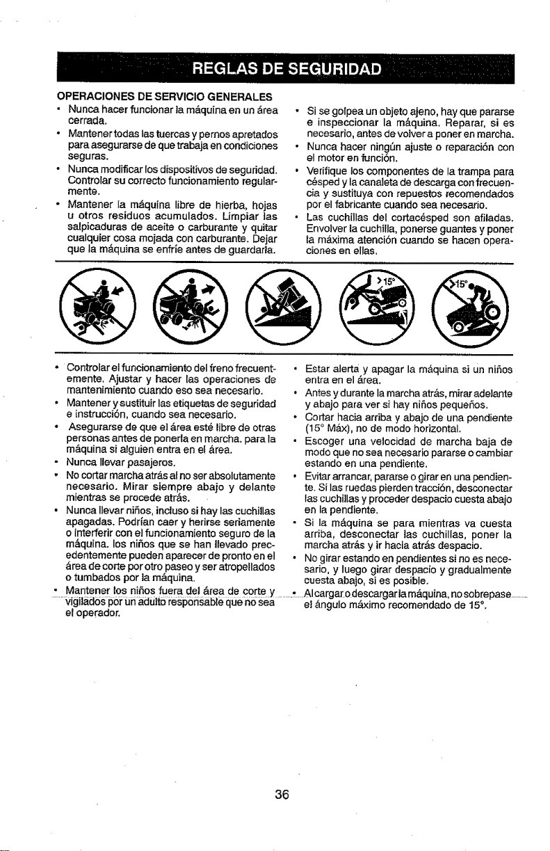
OPERACIONES DE SERVICIO GENERALES
• Nunca hacer funcionar ]a m_quina en un &rea
cerrada,
• Mantener todas Ias tuercas y pemos apretados
para asegurarse de quetrabaja en condiciones
seguras.
• Nunca modiflcar los dispositivos de segu ridad,
Controlar su correctofuncionamiento regular-
mente,
• Mantener Ia m-4,quinalibra de hierba, hojas
u otros residues acumulados. Limpiar ins
sa[picaduras de aceite o carburante y quitar
cualquier cosa mojada con carburante. Dejar
qua la m&quina se enfrie antes de guardaria.
!
i
Si se golpea un objeto ajeno, hay qua pararse
e inspeccionar la m&quina, Reparar, si es
necesario, antes de vo]ver a porter en marcha.
Nunca hacer ning_n ajuste o repamci6n con
el motor en 1unciSn.
Verifique los componentes de la trampa para
c_sped y la canaleta de descarga con frecuen-
cia y sustituya con repuestos recomendados
par el fabricante cuando sea necesado.
Las cuchillas deI ¢ortac_sped son afiladas.
Envolver |a cuchiUa, ponerse guantes y paner
ia m&xima atenci6n cuando se hacen opera-
clones en elias,
@@@@@
• Controlar el funcionamiento deIfreno frecuent-
emente. Ajustar y hacer Ins operaciones de
mantenimiento cuando eso sea necesario.
• Mantener y sustituir Ins etiquetas de seguridad
e instrucci6n, cuando sea necesario.
° Asegurarse de que e] &rea est_ libre de otras
personas antes de poneria en marchao para la
m_.quina si alguien entra en el &tea,
- Nunca Ilevar pasajeros.
, No cortar marcha atr_.sal no ser absolutamente
necesario. Mirar siempre abajo y delante
mientras se precede atr&s.
• Nunca Ilevar niSos, incluso si hay las cuchillas
apagadas. Podr|an caer y herirse seriamente
o interfefir con el funcionamiento seguro de la
m&quina, los nihos qua se han Uevado prec-
edentemente pueden aparecer de pronto en el
_rea de carte par otro paseo y set atropellados
o tumbados par la m__quina.
• Estar alert_( y apagar la m&quina si Un nifos
entra en el _-rea.
• Antes y durante Ia marcha atr&s, mirar adeiante
y abajo para ver si hay nifos pequefos.
• Cortar hacia arriba y abajo de una pendiente
(15 ° Max), no de mode horizontal.
• Escoger una vetocidad de marcha baja de
mode que no sea necesario pararse o cambiar
estando en una pendiente,
• Evitararrancar, pararseogirarenunapendien-
re. Si las ruedas pierden tracciOn, desconectar
ias cuchi]las y preceder despacio cuesta abajo
en la pendiente.
- Si la m&quina se para mientras va cuesta
arfiba, desconectar ins cuchilIas, porter la
marcha atr&s y ir hacia atr&s despacio.
• No girar estando en pendientes si no es nece-
sario, y luego girar despacio y gradualmente
cuesta abajo, si es posible,
• Mantener los nihos fuera del &tea de carte y ...... A .cargarodescargar a m&quina, no sobrepase ..........
......vigil_6s pSr _.J5a_duttoi:esp55§al:)teque n0sea el &ngulo m&ximo recomendado de 15%
el operador,
36
ESPECIFICACIONES DEL PRODUCTO
Capacidad y Tipo 2.5 Galones19.46 L
de Gasoline: Regular Sin Ptomo
Tipo de Aceite SAE 10W30 (sobre 32°F/0_C)
(APt: SG-SL): SAE5W30(deabajo32°F/0 C)
Capacidad de Con Filtro: 51 Oz./1,5 L
Aceite: Sin Filtro: 35 Oz.ii ,05 L
Bujia Champion RC12YC
(Abertura: .030"/0.76 ram)
Sistema de 15 Amps @ 3600 RPM
Carga:
Bater[a: Amp/Hr: 28
Min, CCA: 230
Modelo Tamaflo: U1R
Torsi6n del Perno 45-55 Ft, Lbs./62-75 Nm
de {a Cuchilla:
FELICITACIONES per la compra de su tractor, Ha
side diseflado, p[aniflcadoy fabricado pare darle la
mejor confiabilidad y el mejor rendimiento posible.
En el case de que se encuentre con cualquier
problema que no pueda solucionar _cilmente,
haga el favor de ponerse en contacto con un
centre de servicio Sears o con un otto centre de
servicio cualificado, Cuenta con representantes
bien capacitados y competentes y con las her-
ramientas adecuadas pare darle servicio o pare
reparar este tractor.
Haga el favor de leer y de guardar este manual,
Estas instruc-ciones Ie permitir&n montar y man-
tenor su unidad en forma adecuada. Siempre
observe las "REGLAS DE SEGURIDAD2
RESPONSABIUDADES DEL CL|ENTE
• Lea y observe Ias regtas de seguridad,
• Siga un programa regular de mantenimiento,
cuidado y use de su tractor,
- Siga tas instrucciones descritas en las sec-
clones "Mantenimiento" y "Almacenamiento"
de este manual.
• Utilice prendas de seguridad edecuadas al
manejar la m&quina, incluidos (come mfnimo)
calzado de seguridad, galas protectoras y pro-
tecci6n auditiva. No utilice pantalones cortes
yio calzade abierto cuando corte la hierba,
En el estado de California, la ley exige lo anterior
(Secci6n 4442 del "California Public Resources
Code"). Otros estados pueden center con otras
leyes parecidas. Las 1eyesfederales se aptican
en la tierras federales, Su centre de Servicio m&s
cercano tiene disponible amortiguadores de chis-
pas pare el silenciador. (Vea la secci6n de Partes
de Repuesto en el manual Ingles del duefio,)
AOUERDOS DE PROTECCION PARA
LA R EPARAClON
Congratulaciones per su buena compra. Su
nuevo producto Craftsman® est& diseSado y
fabricado para funcionar de mode fiable per
touches a_os. Pete come redes los productos.
puede necesitar alguna reparaci6n de tanto en
tanto. En este case tenor un Acuerdo de Protec-
ci6n pare la Reparaci6n puede hacedes ahorrar
dinero y fastidios,
Compre ahora un Acuerdo de Protecci6n pare Ia
Reparaci6n y prot6gese de molestias y gastos
inesperados,
Un Acuerdo incluye los puntos siguientes:
• Servicio experte de nuestros 12.000 espe-
cialistas profesionales en la reparaci6n.
• Servicio ilimitado sin cargo alguno para
las partes y la mano de obra sobre todas las
reparaciones garantizadas,
• 8ustituci6n del producto si su producto
garantizado no puede ser arreglado,
° Desouento de110% sobre el precio cordente
del servicio y de las partes relatives el servicio
no cubiertas per el acuerdo; tambi_n el 10%
menos sobre el precio corriente de un control
de mantenimiento preventive,
• Ayuda r_pida per tel6fono- soporte telef6ni-
co per parte de un representante Sears sobre
productos que requieren un arreglo en case, y
adem&s una programaci6n sobre los arreglos
m&s convenientes.
Cuando se ha comprado el Acuerdo, basra con
una Ilamada telef6nica para programar el servicio,
Puede Ilamar cuando quiera, dia y noche o fijar
en linea una cite para obtener el servicio, Sears
tiene m&s de 12.000 especialistas profesionales
en la reparaci6n, que tienen acceso a m&s de
4,5 milIones de partes y accesofios de calidad.
_;._informe sier_pre=a,algt]ien de que sedispone ..........Este esel tipo de prefesionalidad con que puede ........
a cortar ta hierba en el exterior, contar pare ayudar a alargar la vide del pro-
_&,DVERTENCIA: Este tractor viene equipado
con un motor de combusti6n interne y no se debe
usar sobre, ocerca, de un terreno no desarrollado
cubierto de bosques, de arbustos o de c6sped,
o menos que el sistema de escape del motor
venga equipado con un amortiguador de chispas
que cumpla con tas leyes locales o estatales {si
existen), Si se usa un amortiguador de chispas,
et operador debe mantenerlo en condiciones de
trebajo eficientes.
ducto que acaba de comprar, per touches aries.
iCompre hey su Acuerdo de Protecci6n pare la
Reparaci6n!
Se aplican algunas limitaciones y exclusiones.
Para conocer los precios y toner mds Infor-
macibn, Uame al 1-800-827-6655.
SERVICIO DE INSTALACION SEARS
Para /a insta/aci6n profesiona/ Sears de apara-
tos de casa, puertas de garaje, calentadores de
agua y otros importantes artlculos pare la case,
en U,S,A Ilamar a
1-800-4-MY-HOME®
37
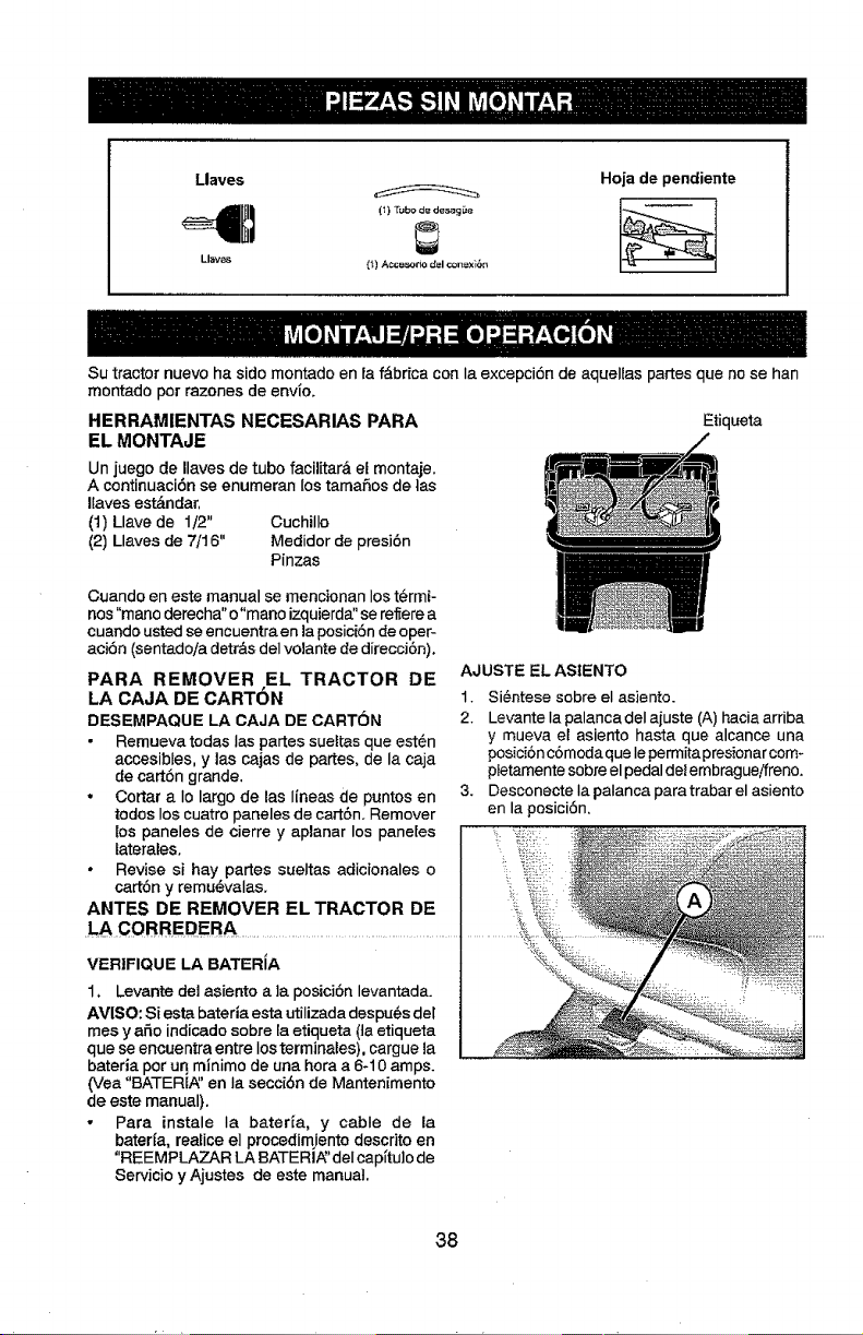
Llaves
(1) Tubo de des_g _e
Llaves {_} AccBso_o d_l con_xidn
Hoja de pendiente
Su tractor nuevo ha sido montado en la f_.brica con Ia excepci6n de aquelias parses que no se han
montado por razones de envfe.
HERRAMIENTAS NECESARIAS PARA
EL MONTAJE
Un juego de Ilaves de tube facilitar& et montaje.
A continuaci6n se enumeran los tamafios de tas
liaves est&ndar,
(1) Llave de 1/2" Cuchillo
(2) Llaves de 7/16" Medidor de presi6n
Pinzas
Etiqueta
Cuando en este manual se mencionan los termi-
nos "mano derecha" o "mano izquierda" se re_erea
cuando usted se encuentra en la posici6n deoper-
aci6n (sentado/a detrds del volante de direcci6n).
PARA REMOVER EL TRACTOR DE
LA CAJA DE CARTON
DESEMPAQUE LA CAJA DE CARTON
• Remueva todas las partes sueltas que est6n
accesibtes, y las cajas de partes, de la caja
de cart6n grande.
• Cortar a Io largo de las I{neas de puntos en
todoslos cuatro paneles de ca_t6n. Remover
{os paneles de cierre y aplanar los pane[es
laterales.
• Revise si hay partes sueitas adicionales o
cart6n y remu_valas.
ANTES DE REMOVER EL TRACTOR DE
CORREDERA
VERIFIQUE LA BATER{A
1, Levante del asiento a ]a posici6n levantada.
AVISO: Si esta bateria esta utilizadadespu6s de[
mes y a_o indicado sobre la etiqueta (ta etiqueta
que se encuentra entre los terminales), cargue la
bateria por un minimo de una hora a 6-10 amps.
(Vea "BATER[_' en Ia secci6n de Mantenimento
de este manual).
• Para instale Ia bater{a, y cable de la
bater{a, reaHcee] procedirnientodescrito en
"REEMPLAZAR LA BATERI_' deI eap{tulo de
Servicio y Ajustes de este manual.
AJUSTEELASIENTO
1. Si@ntesesobre el asiento.
2. Levante Ia palanca del ajuste (A) hacia arriba
y mueva e! asiento hasta que alcance una
posici6n c6modaque Iepermitapresionar com-
pietamente sobre el pedaldel embragueifreno.
3. Desconecte Ia palanca paratrabar el asiento
en la posici6n.
i!iiii
38
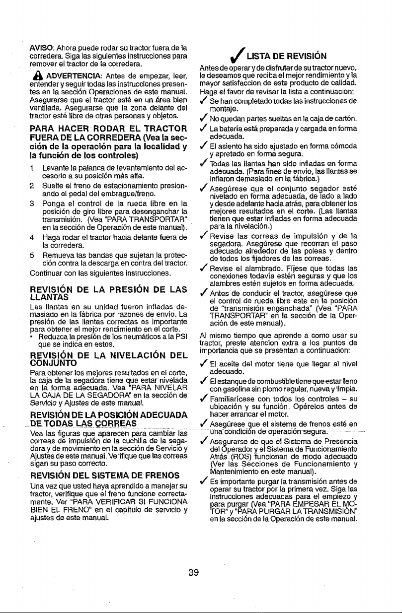
AVISO: Ahora puede rodar su tractor fuera de la
corredera. Siga Ias siguientes instrucciones para
remover el tractor de la corredera.
ADVERTENOIA: Antes de empezar, leer,
entender y seguir todas las instrucc[ones presen-
tesen la secci6n Operaciones de este manual.
Asegurarse que el tractor est_ en un &tea bien
ventilada. Asegurarse que la zona delante del
tractor est6 libre de otras personas y objetos.
PARA HACEFI RODAR EL TRACTOR
FUERA DE LA CORREDERA (Vea |a sec-
ci6n de la operacl6n para |a local|dad y
la funci6n de los controles)
1 Levante la palanca de levantamiento del ac-
cesorio a su posici6n m&s alta.
2 Suelte el frene de estacionamiento presion-
ando el pedal del embrague/freno.
3 Ponga el control de la rueda libre en la
posici6n de giro libre para desenganchar Ia
transmisi6n. (Vea "PARA TRANSPORTAR"
en Ia secci6n de Operaci6n de este manual).
4 Haga rodar el tractor hacia delante fuera de
la corredera.
5 Remueva las bandas que sujetan la protec-
ci6n contra Ia descarga en contra deI tractor.
Continuar con las siguientes instrucciones.
REVISION DE LA PRES|ON DE LAS
LLANTAS
Las Ilantas en su unidad fueron infladas de-
masiado en Ia f&brica per razones de envio. La
presi6n de las Ilantas correctas es importante
para obtener el meier rendimiento en el corte.
• Reduzca la presi6n de los neum&ticos a la PSI
que se indicaen estos.
REVISION DE LA NIVELACION DEL
CON JUNTO
Para obtener los mejores resultados en el corte,
la caja de la segadora tiene (]ue estar nivelada
en la forma adecuada. Vea 'PARA N1VELAR
LA CAJA DE LA SEGADOR_' en la secci6n de
Servicio y Ajustes de este manual.
REVISION DE LA POSICl6N ADECUADA
J LISTA DE REVISI6N
Antes de operar y dedisfrutar de sutractornuevo,
le deseamos que reciba el meier rendimiento y ]a
mayorsatisfaction de este productode ealidad,
Haga el favor de revisar la lista a continuacien:
J" Se hancompletado todas Ias instruccionesde
mon_je,
Vr Noquedan partes suettas en Ia cajade cart6n.
t/" Labateria est&preparada y cargada en forma
adecuada.
El asiento ha side ajustado en forma c6moda
y apretado en forma segura,
J" Todas las Ilantas han side infladas en forma
adecuada. (Para fines de envlo, Ias liantas se
inflarondemasiado en ta f_.brica.)
vf AsegQrese que el conjunto segador est_
nivelado en forma adecuada, de lade a lade
y desde adelante hacia atr__s,para obtener los
mejores resultados en el corte. (Las ltantas
tienen que estar infladas en forma adecuada
para la nivelaci6n.)
V( Revise Ias correas de impulsi6n y de la
segadora. AsegQrese que recorran el paso
adecuado alrededor de las poleas y dentro
de todos los fijadores de las correas.
V_ Revise el alambrado. Ffjese que todas las
conexiones todavia est_n seguras y que los
alambres estOn sujetos en forma adecuada,
i/" Antes de conducir el tractor, aseg0rese que
el control de rueda libre este en la posici6n
de "transmisi6n enganchada" (Vea "PARA
TRANSPORTAR" en la secci6n de Ia Oper-
aci6n de este manual),
AI mismo tiempo que aprende a come usar su
tractor, preste atencion extra a los puntos de
[mportancia que se presentan a continuacion:
i/El aceite deI motor tiene que tlegar al niveI
adecuado.
J El estanquede combustibletiene queestar lIeno
con gasolina sin plomoregular, nueva ylimpia.
t/" Familiaricese con todos los contro[es - su
ubicaci6n y su funci6n. Op6relos antes de
hacer arrancar el motor.
.....DE TOD&S. LASCO!].REAS Vq Aseg0rese que el sistema de frenos est_ en
Vea las figuras que aparecen para cambiar ia.s ............ unacondici6nde operaci6n segura_ ....................
correas de impuLsi6n de la cuchilla de la sega- J" Asegurarse de que el Sistema de Presencia
dora y de movimiento en la secci6n de Servicio y de10perador y el Sistema de Funcionamiento
A_ustesde este manual. Verifique que las correas Atr&s (ROS) funcionan de mode adecuado
sigan su paso correcto. (Vet las Secciones de Funcionamiento y
tVtantenlmlento en este manual)
REVISION DEL SISTEMA DE FRENOS ' " "
Una vez que usted haya aprendido a manejar su t/Es importante purgarla transmisi6nantes de
tractor, verifique que el freno funcione correcta- operar su tractor per la primera vez. Siga tas
instruccionesadecuadas para el empiezo y
mente. Vet "PARA VERIFICAR St FUNCIONA para purgar (Vea "PARA EMPESAR EL @O-
BIEN EL FRENO" en el capltulo de servicio y TOR" y"PARA PURGAR LATRANSMISION"
ajustes de este manual, en Ia secci6n de ta Operaci6n de este manual.
39
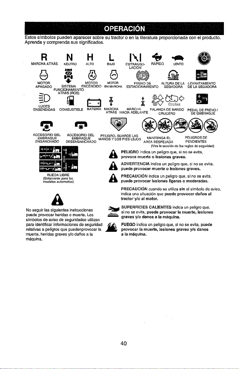
Estos simbolos pueden aparecer sobre su tractor o en la literatura proporcionada con e] producto.
Aprenda y comprenda sus significados.
R
MARCHAATR._S
6
MOTOR
APAGADO
LUCES
ENSENDIDAS
ACCESORIODEL
EMBRAGUE
ENGANCHADO
N H L Ikl
NEUTRO ALTO 8AJO ESTRANGU- Ri_,PIDO LENTO
LACION
" 45 (.®) N
MOTOR MOTOR FNENO DE ALTURA DE LA LLCVANTAMtENTO
SISTEMA ENCENOIDO ENMARCI-IA ESTACEONAM_ENTOSEGADORA DELA SEGADORA
FUNG{QNAMIENTO
ATRAS (ROB)
COM81JSTIBLE BATERIA MARCHA MARCHA PALANCA DE MANOO PEDAL DE FRENO/
ATRA8 HAC|A ADELANT I:: CRUCERO DE EMBRAGUE
ACCESORIODEL PELIGRO,GUARDELAS
EMBRAGUE MANOSY LOSPiESL_JOS MANTENGAEL PELIGROSDE
DESENGANCHADO AREADESPEJADA PEN'DIENTES
(Vea laseCC_6nde laSregtas de seguridad)
PELIGRO ;ndica an peligro que, si no se evita,
provoca muerte o lesiones graves.
ADVERTENCIA indica un peligro que, si no se evita,
puede provocar muerte o lesiones graves.
PRECAUCION indica un peligro que, si no se evita,
puede provocar {esiones ligeras o moderadas.
RUEDA LIBRE
($olamente p_ra los
modelos automati;o)
&
No seguir las siguientes insttucciones _1_
puede provocar heridas o muerte. Los ,_,_,,..---=
simbolos de aviso de seguridadse utilizan
para identificar ir_formacionesde segur_dad /._.
relativas a peligros que puedenprovocar ta
muerte, heridas graves y/o daSos a Ia
m&quina.
PRECAUCION cuando se utiliza sin el simbolo de aviso,
indica una situaci6n que puode provocar da6os al
tractor y/o aI motor.
SUPERFICIES CALIENTE8 indica un peligro que,
si no se evita, puede provocar la muerte_ [esiones
graves y/o danos a la maquina,
FUEGO indica un peligro que, si no se evita, puede
provocar la muerte, lesiones graves yto danos
a la mdquina.
4O
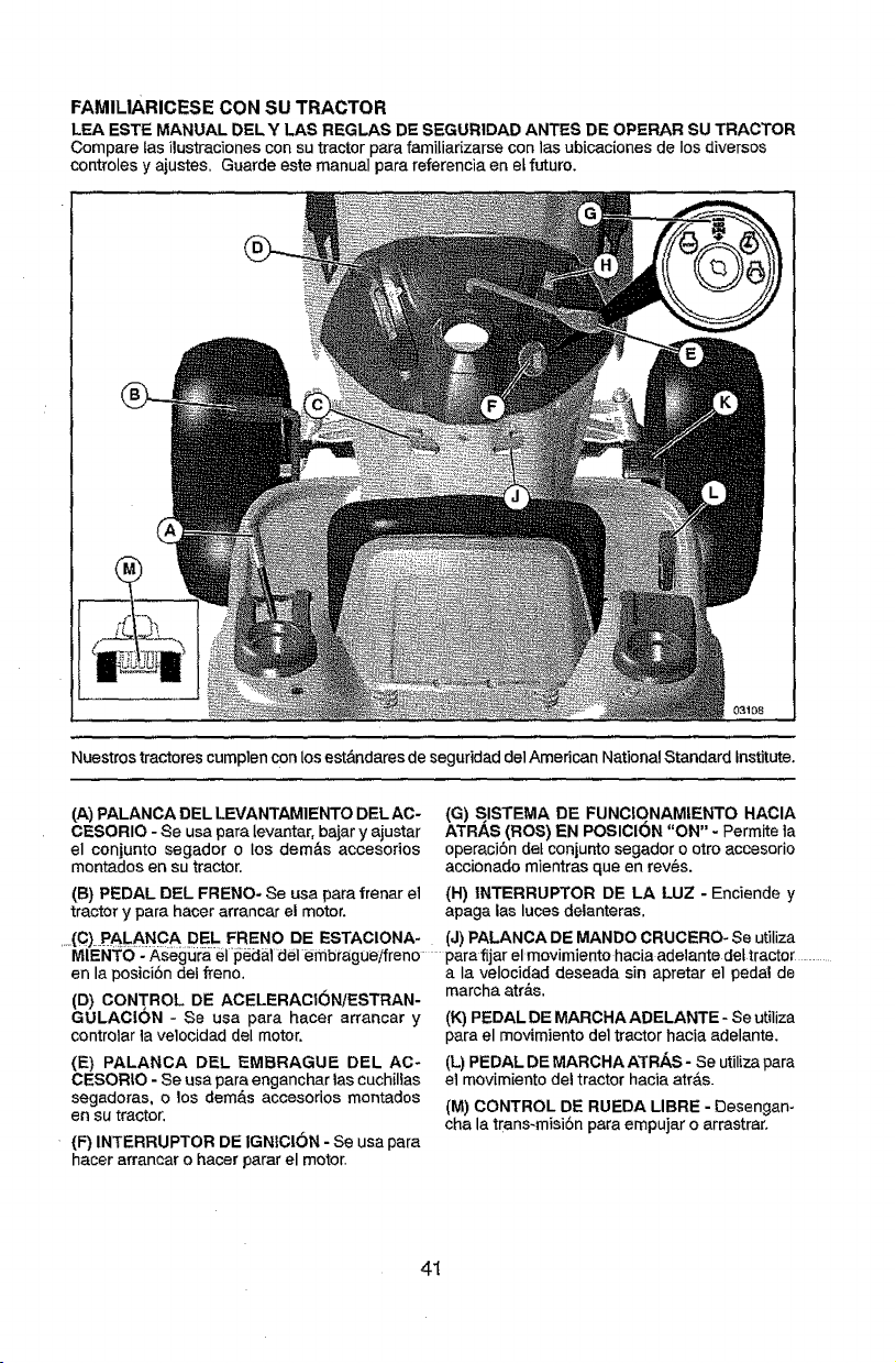
FAMILIARICESE CON SU TRACTOR
LEA ESTE MANUAL DELY LAS REGLAS DE SEGURtDAD ANTES DE OPERAR SU TRACTOR
Compare las ilustraciones con su tractor para familiarizarse con las ubicaciones de los diversos
controles y ajustes. Guards este manual para referencia en et futuro.
Nuestros tractores cumplen conios est&ndares de seguridad del American National Standard institute.
(A) PALANCA DEL LEVANTAMIENTO DEL AC- (G) SISTEMA DE FUNCIONAM|ENTO HACIA
CESORIO - Se usa para ievantar, bajar y ajustar ATRAS (ROS) EN POSICI6N "ON" -Permite ta
el conjunto segador o los dem&s accesorios operaci6n det conjuntosegador o otto accesorio
montados en su tractor, acoionadomientras queen rev_s.
(B) PEDAL DEL FRENO- Se usa para frenar el (H) |NTERRUPTOR DE LA LUZ - Enciends y
tractor y para hacer arrancar el motor, apaga las luces delanteras.
=(C).PALANCA DEL FRENO DE ESTACIONA- (J) PALANCA DE MANDO CRUCERO- Se utiliza
MIENTO L_segu?a =eI=]_edaldelembraguej'freno _ para _tjarel movimiento hacia adelante deltractor ..........
en la posiciSn det freno.
(D) CONTROL DE ACELERAC|6NJESTRAN-
GULAQION - Se usa para hacer arrancar y
controlar la velocidad del motor.
(E) PALANCA DEL EMBRAGUE DEL AC-
CESOR|O - Se usa para enganchar las cuchiltas
segadoras, o los dsmds accesorios montados
en su tractor.
(F) INTERRUPTOR DE IGNIOION - Se usa para
hacer arrancar o hacer parar el motor.
a la velocidad deseada sin apretar el pedal de
marcha atr&s.
(K) PEDAL DE MARCHA ADELANTE - Se utiliza
para el movimiento de1tractor hacia adelante.
(L) PEDAL DE MARCHA ATRAS - Se utiliza para
el movimiento del tractor hacia atr&s.
(M) CONTROL DE RUEDA LIBRE - Desengan-
cha la trans-misi6n para empujar o arrastrar.
41
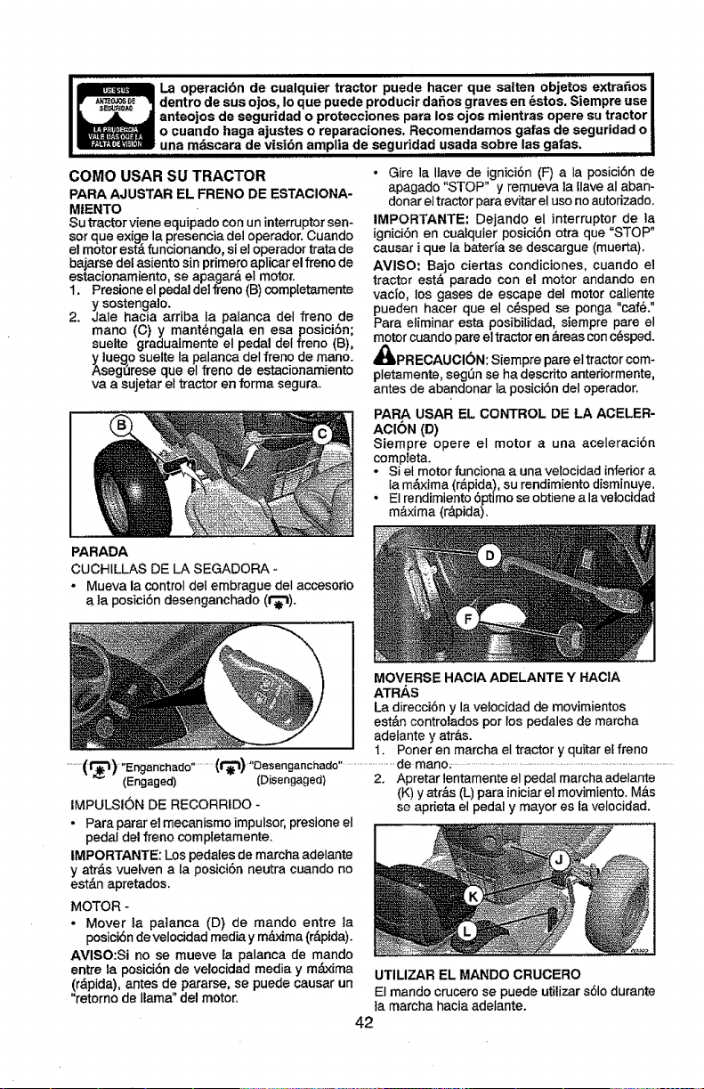
i llll ii
La operactbn de cualquier tractor puede hacer que satten objet0s extra_os
lr _ lj dentro de sus ojos, Ioque puede producir da_os graves en _stos, Siempre use
ll_ anteojos de seguridad o protecciones para los ojos mientras opere su tractor
o cuando haga ajustes o reparaciones. Recomendamos gafas de seguridad o
_,,una mdscara de visi6n amplia de seguddad usada sobre las gafas,
COMO USAR SU TRACTOR
PARA AJUSTAR EL FRENO DE ESTACIONA-
MIENTO
Su tractor viene equipado con un interruptor sen-
sor que exige la presencia del operador. Cuando
el motor est&funcionando, si el operador trata de
bajarse del as[ento sin primero aplicar el freno de
estacionamiento, se apagar& el motor.
1, Presione el pedal delfreno (B) completamente
y sostenga]o,
2, Jale hacia arriba La palanca del freno de
mano (C) y mant_ngala en esa posici6n;
suelte graduatmente el pedal det freno (B),
y luego suelte Ia palanca deI freno de mano.
Aseg_rese que el freno de estacionamiento
va a sujetar el tractor en forma segura,
• Gire la Itave de ignici6n (F) a Ia posici6n de
apagado "STOP" y remueva la Ilave al aban-
donar eltractor para evitar el uso no autorizado,
IMPORTANTE: Dejando el interruptor de ]a
ignici6n en cualquier posici6n otra que "STOP"
causar i que la bateda se descargue (muerta).
AMISO: Bajo ciertas condiciones, cuando el
tractor est& parado con el motor andando en
vac_o, los gases de escape del motor caliente
pueden hacer que el c@sped se ponga "caf_."
Para eliminar esta posibilidad, siempre pare el
motor cuando pare el tractor en &reas con c@sped.
_,PR ECAUCI6N: Siempre pare el tractor com-
pletamente, segt3n se ha descrito anteriormente,
antes de abandonar la posici6n del operador.
PARA USAR EL CONTROL DE LA ACELER-
ACION (D)
Siempre opere el motor a una aceleraci6n
compIeta,
- Si el motor funciona a una vetocidad inferior a
la m_xima (r&pida), su rendimiento disminuye.
• EI rendimiento 6ptimo se obtiene a lavelocidad
m&xima {r_.pida).
PARADA
CUCHILLAS DE LA SEGADORA -
° Mueva la control del embrague deI accesorio
a la posici6n desenganchado (t_),
MOVERSE HACIA ADELANTE Y HACIA
ATRAS
La direcci6n y la vetocidad de movimientos
est&n controlados pot tos pedales de marcha
adelante y atr&s.
1. Poner en marcha el tractor y quitar el freno
......(r_3)"Engarrchado..........(f_) "Oesenganchado........................de manor-...................................................................................
-'_" (Engaged) (Disengaged) 2. Apretarlentamenteelpedalmarchaadelante
{K) y atr&s (L) para iniciarel movimiento, M&s
IMPULSION DE RECORRIDO - se aprieta el pedal y mayor es la velocidad,
• Para parar el mecanismo impulsor, presione eI
pedal del freno compietamente,
IMPORTANTE: Los pedaies de marcha adelante
y atr&s vuelven a la posioi6n neutra cuando no
est&n apretados.
MOTOR -
- Mover la palanca (D) de mando entre ta
posiciSn de velocidad media y m_ma (r&pida).
AVISO:Si no se mueve la palanca de mando
entre la posici6n de velocidad media y m#,xima UTILIZAR EL MANDO CRUGERO
(r&pida), antes de pararse, se puede causar un
"retomo de llama" del motor, El mando crucero se puede utilizar s61odurante
]a marcha hacia adelante.
42
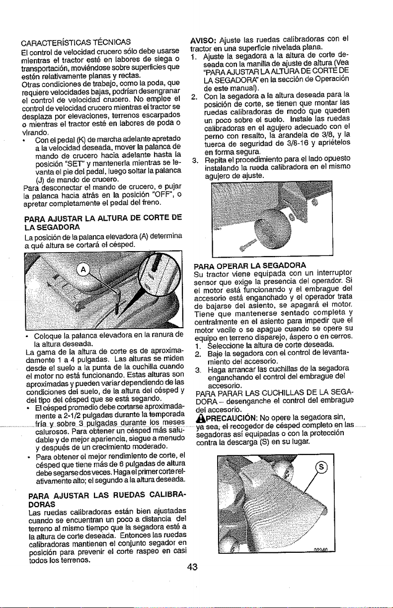
CARACTERiSTIOASTE_CNIOAS
Elcontroldevelocidadcruceros61odebeusarse
mientraseltractorest4_enlaboresdesiegao
transportacJ6n,movJ#ndosesobresuper_ciesque
est6n relativamente planas y rectas.
Otras condiciones de trabafo, come la poda, que
requiere velocidades bajas, podrlan desengranar
el control de velocidad crucero. No emplee el
control de velocidad crucero mientra8 eftractor se
desplaza per elevaciones, terrenos escarpados
o mientras el tractor est6 en labores de poda o
virando.
• Con el pedal (K)de marcha adelante apretado
a la velocidad deseada, mover la palanca de
mando de crucero hacia adelante hasta la
posici6n "SET' y mantenerla mientras se le-
vanta el pie def pedal, luego soltar la palanca
(J) de mando de crucero.
Para desconectar el mando de crucero, e pujar
la palanca hacia atr&s en la posici6n "OFF", o
apretar comptetamente et pedal del freno.
PARA AJUSTAR LA ALTURA DE CORTE DiE
LA SEGADORA
La posici6nde la palanca elevadora (A) determina
a qua' altura se cortar&el c_sped.
AVISO: Ajuste las ruedas calibradoras con el
tractor en una superficie nivelada plana.
1. Ajuste Ia segadora a la altura de corte de-
seada con Ia manilta de ajuste de altura (Vea
"PARA AJUSTAR LA ALTURA DE CORTE DE
LA SEGADOR_:' en fa secci6n de Operaci6n
de este manual).
2. Con la segadora a la aftura deseada para la
posici6n de corte, se tienen que montar las
ruedas calibradoras de mode que queden
un poco sobre el suelo. Instale Ias ruedas
calibradoras en el agujero adecuado con el
perno con resatto, la arandela de 3/8, y Ia
tuerca de seguridad de 3/8-16 y apri6telos
en forma segura,
3. Repita el procedimiento para el Iado opuesto
instalando ia rueda calibradora en el mismo
agujero de ajuste.
• Coloque Ia palanca etevadora en la ranura de
la altura deseada.
La gama de ta altura de corte es de aproxima-
damente 1 a 4 pulgadas. Las alturas se miden
desde el suelo a la punta de la cuchilla cuando
el motor no est& funcionando. Estas alturas son
PARA OPERAR LA SEGADORA
Su tractor viene equipada con un interrupter
sensor que exige la presencia del operador. Si
el motor est& funcionando y el embrague deI
accesorio est,. enganchado y el operador trata
de bajarse del asiento, se apagar& et motor.
Tiene que mantenerse sentado completa y
centralmente en el asiento para impedir que el
motor vacile o se apague cuando se opere su
equipo en terreno disparejo, &spore o en cerros.
t. Seleccione la altura de corte deseada.
2. Baje la segadora con et control de levanta-
miento det accesodo.
3. Haga arrancar las cuchiltas de la segadora
aprox[madas y pueden variar dependiendo de las enganchando el control del embrague del
accesorio.
condiciones del suelo, de Ia altura del c4_spedy
del tipo del c6sped que se est& segando. PARA PARAR LAB CUCH1LLAS DE LA SEGA-
* _! _,z,_n,d,_romedi:_a,=hecor_rse =r,roxima,_a DORA - desenganche el control del embrague
mente a 2-1/2 pulgadas durante Iatemporada _'____ " o
. 4BkPH_'uAUCION ' No opere Ia segaaora sin
........................frla.y.sobre_.3pu!gadas durante los meses . _" ..... ,.
ya sea el recogeaor de cespea comptezo en las
calurosos.Para obtener-U-11-6_sped'm_iSsalu: ........ . _ " , _ " . . ........
dable y de meier apafiencia, siegue a menudo segadoras as_ equtpaaas o con la pro[ecc[on
y despu4_sde un crecimiento moderado, contra la descarga (S) en su lugar.
• Para obtener el meier rendimiento de code, el
c_sped que tiene robs de 6 pulgadas de altura
debe segarse dos veces. Haga eI primercorte rel-
ativamente alto; el segundo a Ia altura deseada.
PARA AJUSTAR LAS RUEDAS CALIBRA-
DORAS
Las ruedas calibradoras est&n bien ajustadas
cuando se encuentran un poco a distancia del
terreno al mismo tiempo que la segadora est_ a
la altura de corte dese_,da. EntoncesIas ruedas
calibradoras mantienen el conjunto segador en
posici6n para prevenir el corte raspeo en casi
todos los terrenos.
43
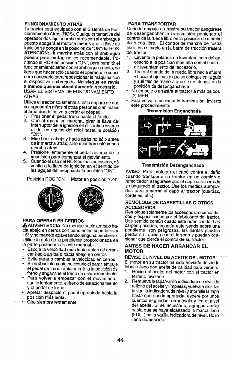
FUNCIONAMIENTOATR/_,S
Tu tractor est& equipado con el Sistema de Fun-
oionamiento Atr&s (ROS). Cualquier tentativa deI
operador de viajar marcha atr_.scon el embrague
puesto apagar& el motor a menos que la liave de
ignici6nse ponga en la posici6n de "ON" del ROS.
ATENClON: Ir marcha atr_s con el embrague
puesto para cortar, no es recomendable. Po-
niendo el ROSen posici6n "ON", para permiUr el
funcionamiento atr&s con el embrague puesto, se
tiene que hacer s6Jocuando el operador lo consi-
dera necesario para reposicionar la m&quina con
e! dispositivo embragado. No siegue en rev_s
a menos que sea absotutamente necesario.
USAR EL SISTEMA DE FUNCIONAMIENTO
ATRAS -
Utilioe el tractor sotamente si est& seguro de que
no ingresar_n nifios ni otras personas o animales
al #.rea donde se va a cortar el c@sped.
t. Presionar el pedal freno hasta el fondo.
2. Con el motor en marcha, girar Ia Ilave deI
interruptor de la ignici6n en el sentido inverso
al de las agujas deI reloj hasta la posici6n
"ON".
3 Mire hacia abajo y hacia atr_s no s6Io antes
de ir marcha atr_.s,sino mientras est_ yendo
marcha atr_.s.
4. Presione Ientamente el pedal reverso de la
Jmpulsi6n para comenzar el movimiento.
5, Cuando el uso del ROS es m&s necesario, d6
vuelta a la Ilave de ignicibn en el sentido de
las agujas deI reloj hasta la posici6n "ON".
Posici6n ROS "ON" Motor en posiciSn "ON"
PARA OPERAR EN CERROS
_ILADVERTENCIA: No maneje hacia arriba o ha-
cia abajo en cerros con pendientes superiores a
15° y nomaneje atravesando ninguna pendiente.
Utilice la gula de Ia pendiente proporcionada en
Ia parte posteriora de este manual.
• Escoja Ia velocidad m&s lenta antes de arran-
• Evite parar o cambiar la velocidad en cerros.
• Si esabsolutamente necesario ef parar,empuje
el pedal de freno r&pidamente a la posici6n de
freno y enganche el freno de estacionamiento,
• Para volver a empezar con el movimiento,
suelte lentamente, el freno de estacionamiento
y el pedal de freno.
• Apretar despacio el pedal apropiado hasta la
posici6n m&s lent&
• Gire siempre lentamente.
PARA TRANSPORTAR
Cuando empuje o arrastre su tractor aseg_rese
de desenganchar la transmisi6n poniendo el
control de ta rueda libre en la posiciOn de marcha
de rueda libre. El control de marcha de rueda
libre esta situado en la barra de tracci6n trasera
deI tractor.
1. Levante la palanca de tevantamiento det ac-
cesorio a la posiciOn m_.s alta con el control
de Ievantamiento deI accesorio.
2. Tire del mando de la rueda libre hacia afuera
y hacia abajo hasta que se coloque en laguia
y sueltalo de manera que se mantenga en la
posici6n de desenganchada,
• No empuje o arrastre el tractor a m&s de dos
(2) MPH.
. Para volver a accionar la transmisi6n, invierta
este procedimiento.
Transmisi6n Enganchada
Transmisi6a Desenganchada
AVISO: Para proteger el cap6 contra el daSo
cuando transporte su tractor en un cami6n o
remo_cador,aseg0rese que el cap5 est6 cerrado
y asegurado al tractor. Use los medios apropia-
dos para amarrar el cap6 at tractor (cuerdas,
cordeles, etc.).
REMOLQUE DE CARRETILLAS O OTROS
ACCESORIOS
Remolque solamente los accesorios recomenda-
dos y especificados pot el fabricante del tractor.
Use sentido comfin cuado este remolcando. Las
cargas pesadas, cuando este yendo sobre una
pendiente, son peligrosas, las Ilantas pueden
perder su tracci6n con el terreno y pueden oca-
s]onar que pierda el control de su tractor.
ANTES DE HAOER ARRANOAR EL
MOTOR
El motor en su tractorha sido enviado desde la
f&brica !Ieno con aceite de calidad para verano.
1. Revise el aceite deI motor con el tractor en
terreno nivelado.
2, Remueva la tapajvarilta indicadora de nivelde
relleno del aceite y Iimpielas, vuelva a insertar
la vadlla indJcadora de nivel y atorni]le latape
hasta que quede apretada, espere por unos
cuantos segundos, remu@vala y lea el niveI
det aceite. Si es necesario, agregue aceite
hasta que se haya alcanzado la marca lleno
(FULL) en la varilla indicadorade nivel. No Io
Ilene demasiado.
44
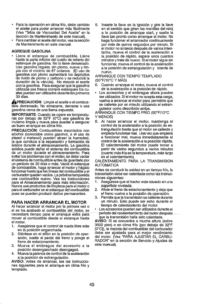
• Para la operacion en clima frio, debe cambiar
el aceite para poder arrancar rn&s f&cilmente
(Vea "Tabla de Viscosidad Del Aceite" en ta
secci6n de Mantenimento de este manual).
• Para cambiar eI aceite del motor, vea ta secci6n
de Mantenimento en este manual.
AGREGUE GASOLINA
• Llene el estanque de combustible. Llene
hasta Ia porte inferior del cuello de relleno del
estanque de gasolina, No Io tlene demasiado.
Use gasolina regular, sin plomo, nueva y lirn-
pia con el minimo de 87 octanos. (El uso de
gasolina con plorno aumentar& los dep6sitos
de 6xido de p!omo y carbono y se reducirA la
duraci6n de la v&Ivula). No mezcle el aceite
con la gasolina. Paraasegurar que [agasolina
utilizada sea fresca compre estanques los cu-
ales puedan ser utilizados durante los pdmeros
30 dias.
_PRECAUCI6N: Limpie el aceite o el combus-
tible derramado. No alrnacene, derrame o use
gasolina cerca de una llama expuesta.
|MPORTANTE: Cuando se opere en ternperatu-
ras por debajo de 32°F (0°C) use gasolina de
invierno limpia y nueva para auedar a asegurar
un buen arranque en clima frio.
PRECAUCION: Combustibles mezclados con
alcohol (conocidos como gasohol, o el uso de
etanol o metanol) pueden atraer Ia humedad,
la que conduce a ia separaci6n y formacibn de
&cfdos durante el almacenamiento. La gasolina
acidica puede daSar el sistema del combustible
de un motor durante el alrnacenamiento. Para
evitar los problemas con el motor, se debe vaciar
el sistema de combustible antes de guardarlo pot
un per|odo de 30 di'as o re&s. Vac_e el estanque
de combustible, haga arrancar el motor y h&galo
funcionar hasta que las lineas del combustible y el
carburador queden vacios. La pr6ximaternporada
use combustible nuevo. Vea los tnstrucciones
para el Atmacenamiento para m&s informaci6n.
Nunca use productos de timpieza para el motor o
para el carburador en el estanque de1combustible
pues se pueden producir dodos permanentes.
PARA HACER ARRANCAR EL MOTOR
5. lnserte ia tlave en Ia ignicibn y gire la tlave
en et sentido que giran Ias maniUas del reloj
a Ia posici6n de arranque start, y suelte Ia
Ilave tan pronto como arranque el motor. No
haga funcionar el arrancador continuamente
por m&s de quince segundos por minuto. Si
el motor no arranca despu6s de varios inten-
tarlos, mueva el control de Ia aceleraci6n a
Ia posici6n de r&pido, espere unos cuantos
minutos y trate de nuevo. Si el motor sigue sin
funcionar, mueva el control de la aceteraci6n
a Ia posici6n de estrangulaci6n y intente de
nuevo,
ARRANQUE CON TEMPO TEMPLADO
(50°F/10°0 Y MAS)
6. Cuando arranque el motor, rnueva el control
de ia aceleraci6n a la posici6n de r&pido.
* Los accesorios y el embrague ahora pueden
ser utilizados. Si el motor no acepta esta cargo,
vuelva a arrancar el motor para permitirle que
se caiiente por un minuto utilizando el estran-
gulador come desoribido arriba.
ARRANQUE CON TIEMPO FR{O (50°F/10°C
Y MENOS)
6. At hater arrancar el motor, rnantenga el
control de ta aceleraci6n a la posicibnde es_
trangulaci6n basra que el motor se caliente y
empiezefuncionar mat. Unavezque empieze
a funcionar rnal, mueva inrnediatamente el
control de Ia aceleraci6n a Ia posici6n r&pida.
El calentamiento deI motor puede tomara
partir de varies segundos a varios minutos
(cuanto rn&sfria es latemperatura, m&s largo
es el calentarniento).
CALENTAMIENTO PARA LA TRANSMISION
AUTOMATICA
Antes de conducir la unidad en un tiempo fr{o, la
transmisiOn debe ser calentada como las instruc-
ciones siguientes:
1. AsegOrese que el tractor este situado en una
superficie nivelada.
2. Aiivie el freno de estacionamiento y deje que
el freno vuelva a ta posioi6nde operaci6n.
3. Permita que Ia transmisi6n se caliente durante
un minuto. Esto puede set echo durante el
At hacer arrancar el motor por la primera vez o tiempo de calentamiento del motor.
• h_ _ n m • a t _ • Losaccesoriospuedenserutilizadosduranfeet
stse ...... cabado .el .,o.,.bust_bIe _el too,or.....
penodo det recalentarnlento det motor despu_s
necesitar& tiernpo para el ar_'anqueext_'a para ......... .............
mover el combustible desde el estanque hasta
et motor.
I, Aseg_rese que el control de rueda libre es_e
en la posici6n enganchada.
2. Si6ntase en el sill6n en la posici6nde oper-
aci6n, sueIte e[ pedal det freno y ponga el
freno de estacionamiento.
3. Mueva el embrague det accesorio a la
posici6n desenganchado disengaged.
4. Mueva Ia palanca de controlde la aceleraci6n
a la posici6n de estrangulaci6n.
AVISO: Antes de arrancar, lea las instruccio-
nes siguientes para ef arranque en clima frio y
templado.
que la transmisibn halla sido calentada.
AVISO: Si se encuentra a mucha altura (sobre
3000 pies) o en clima frio (por debajo de 32°F
[0°C]), la mezcta del combustible del carburador
debe set ajustada para el mejor rendimiento
del motor. (Vea "PARA AJUSTAR EL CARBU-
RADOR" en [a secci6n de Servicio y Ajustes de
este manual).
45
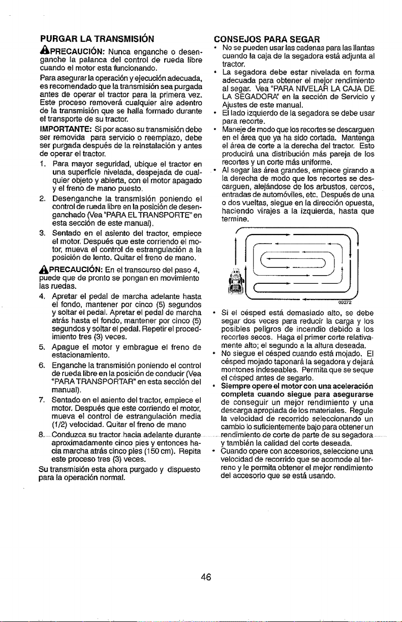
PURGAR LA TRANSMISION
_PRECAUCI6N: Nunca enganche o desen-
ganche Ia palanca del control de rueda libre
cuando el motor esta funcionando.
Para asegurar la operaci6n y ejecuci6n adecuada,
es recomendado que la transmisi6n sea purgada
antes de operar el tractor para la primera vez.
Este proceso remover& cualquier aire adentro
de ta transmisibn que se halla formado durante
e! transporte de su tractor.
IMPORTANTE: Si por acaso su transmisi6n debe
ser removida para servJcio o reemplazo, debe
set purgada despu@s de Ia reinstalaci6n y antes
de operar el tractor.
1. Para mayor seguridad, ubique el tractor en
una superficie nivelada, despejada de cual-
quier objeto y abierta, con el motor apagado
y el freno de mano puesto.
2. Desenganche Ia transmisi6n poniendo el
control de rueda libre en la posici6n de desen-
ganchado (Vea "PARA ELTRANSPORTE" en
esta secci6n de este manuaD.
3. Sentado en el asiento del tractor, empiece
el motor. DespuL=sque este corriendo el mo-
tor, mueva el control de estrangulaci6n a la
posici6nde lento. Quitar el freno de mano.
_PRECAUCI6N: En el transcurso del paso 4,
puede que de pronto se pongan en movimiento
las ruedas.
4. Apretar el pedal de marcha adelante hasta
el rondo, mantener por cinco (5) segundos
y soltar el pedal. Apretar el pedal de marcha
atr&s hasta el fondo, mantener pot cinco (5)
segundos y soltar el pedal. Repetir el proced-
imiento tres (3) veces.
5. Apague el motor y embrague el freno de
estacionamiento.
6. Enganche la transmisi6n poniendo el control
de rueda libre en la posici6n de conducir (Vea
"PARA TRANSPORTAR" en esta secci6n del
manual).
7. Sentado en el asiento del tractor, empiece el
motor. Deepu@sque este corriendo el motor,
mueva el control de estrangulaci6n media
(I/2) velocidad. Quitar el freno de mano
CONSEJOS PARA SEGAR
• No se pueden usar lascadenas para las llantas
cuando la caja de la segadora est_ adjunta al
tractor.
• La segadora debe estar nivelada en forma
adecuada para obtener el mejor rendimiento
al segar. Vea "PARA NIVELAR LA CAJA DE
LA SEGADOR,_' en la secci6n de Servicio y
Ajustes de este manual.
• El Iado izquierdo de Ia segadora se debe usar
para recorte.
• Manejede modoque los recortes se descarguen
en el &tea que ya ha sido cortada. Mantenga
el &rea de corte a Ia derecha del tractor. Esto
producir_,una distribuci6n m,_s pareja de los
recortes y un corte m&s uniforme.
AI segar Ias &rea grandes, empiece girando a
Ia derecha de modo que los recortes se des-
carguen, alej&ndose de los arbustos, cercos,
entradas de autom6viles, etc. Despu_s de una
o dos vueltas, siegue en la direcoi6n opuesta,
haciendo virajes a Ia izquierda, hasta que
termine.
£/0272
• Si el cesped est& demasiado alto, se debe
segar dos veces para reducir la carga y los
posibles peligros de incendio debido a los
recortes secos. Haga el primer corte relativa-
mente alto; el segundo a la altura deseada.
• No siegue el c6sped cuando est& mojado. El
c_sped mojado taponar_, la segadora y dejar&
montones indeseables. Permita que se seque
el c6sped antes de segarlo.
• Siempre opereel motorcon una aceleracibn
completa cuando siegue para asegurarse
de conseguir un mejor rendimiento y una
descarga apropiada de los materiales. Regule
la velocidad de recorrido seleccionando un
cambio Io suficientemente bajo para obtener un
8. -.Conduzca su.tractor.hacia adelante durante ..........rendimiento de corte de parte de su segadora .........
aproximadamente cinco pies y entonces ha- y tambi@n la calidad del corte deseada.
cia marcha atr&s cinco pies (I 50 cm). Repita • Cuando opere con accesorios, seleccione una
este proceso tres (3) veces, velocidad de recorrido que se acomode a] ter-
Su transmisi6n esta ahora purgado y dispuesto reno y le permita obtener el mejor rendimiento
para _aoperaci6n normal, deI accesorio que se est& usando.
46
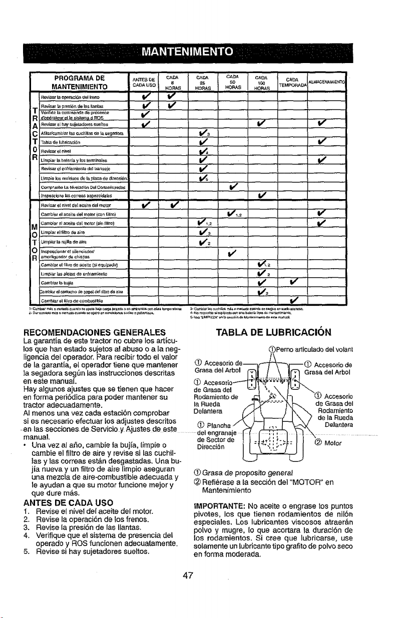
PRO'GRAMADE ..........._r_s_ ''''CAD,' CA_ <_AOA CA_A CA_
MANTENIMIENTO CADA U_O HQSRAS 25 HOF_S50 t_3 TEMPORAD.= ALMt,CE_L_I£NTCJ
HORA_ HOP_
Revis_rla opera;i6n _eI Imno if
l_B_isar_ pre_n d_I_sI_ntas If I_
T w,i_ h.._o _,_6.... Vt .........................................
R d'oo_,l_l!e sislen_ d ROS . ,
,o,,,,°,,oo0,o,,..... , w
IT
0 Revisar _1._el I
R Li_,p_,_._o_,r_i._= ,, . V'
R_is_ el o_ftiamianto dal t_rtsoj_ V #
Umpie k_ mslduos de la pl;_¢a d_ d_e_ci_t_ .... _ ......
lnspar;ck_nelas correa$ #apez_ida_s
FLm_isare_ eJvelctelaceit_ °el molor V _ re,,
Camb]_l el _¢_]Is del motor (c,_ _ fillto) V#_,_ V _
a CamL_i,_" el acei_e d_!,,_oz" (sin _llro)
T Limpi_r la r_illa do ai_ _1#12
0 I_spe_;_r,_t €_I si_e r_]adot!
v'
a amorlig_a0or _e r:h[$pas ..............................
Cambiar el fillm _e,_,¢_ite (€i eQuipa_o) ................. V_. 2
Li_pJ_r _as oI_ias de e_f_en_g (l_ 2
c._..,...i,. !/ I/
_m_i_r el_tl_cho c_ pa_l de1Iiltm _ a_r_ _
C_mbi_r _I lillr0 de comb_$1_ble _l_
RECOMENDACIONES GENERALES
La garantta de este tractor no cubre los articu-
losque han estado sujetos al abuso o a la neg-
Iigenciadel operador. Para recibir todo el valor
de I_ garantia, el operador tiene que mantener
lasegadora seg0n tas instrucciones descritas Grasa(telArbol
en este manual,
Hay algunos ajustes que se tienen que hacer de Grasadel
en forma peri6dica para poder mantener su Rodamientode
tractor adecuadamente, laRueda
AI menos una vez cada estaci6n comprobar Delantem
si as necesario efectuar losadjustes descritos ,,,_ .
.en as secc ones. de Servio O y Ajustes de este _e, P_',_a;a''^^"
..... _ ...............................e g nale .....
"="_=" de,Sectorde
• Unavez al afro, cambie la bujia, [impie o Direcci6n
eambie el filtro de aire y revise si [as cuchil-
las y las correas est&n desgastadas. Una bu-
jia nueva y un filtro de aire limpio aseguran
una mezcla de aire-combustible adecuada y
le ayudan a que su motor funcione mejor y
que dure m&s.
ANTES DE CADA USO
1. Revise el nivel del aceite del motor.
2, Revise Ia operaci6n de los frenos.
3, Revise Ia presi6n de las tlantas,
4. Verifique que el sistema de presencia del
operado y ROS funcionen adecuatamente.
5. Revise si hay sujetadores sueltos.
TABLA DE LUBRICACION
_)Perno axticulado delvolam
Accesorio de
Grasa del Arbol
de Gras_ del
Rodam_ento
de la FIueda
De]antera
(_ Grasa de proposito generai
_) Refi_rase a la secci6n del "MOTOR" en
Mantenimiento
IMPORTANTE: No aceite o engrase los puntos
pivotes, los que tienen rodamientos de nil6n
especiales, Los lubricantes viscosos atraer&n
polvo y mugre, Io que acortara ta duraci6n de
los rodamientos, Si cree que lubriearse, use
sotamente un lubricante tipo grafito de polvoseco
en forma moderada.
47
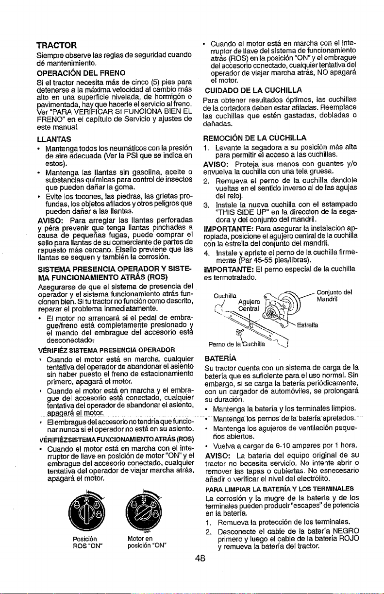
TRACTOR
Siempre observe las regtas de seguridadcuando
d_ mantenimiento.
OPERACION DEL FRENO
Si el tractor necesita m&s de cinco (5) pies para
detenerse a la m&xima velocidad al cambio m&s
alto en una superficie nivelada, de hormig6n o
_avimentada, hayque hacerle eI servicio a! freno.
r "PARA VERIFICAR SI FUNCIONA BIEN EL
FRENO" en el capitulo de Servicio y ajustes de
este manual.
LLANTAS
• Mantenga todos losneum&ticos con la presi6n
de aJreadecuada (Ver la PSi que se indica en
estos).
- Mantenga Ias Ilantas sin gasolina, aceite o
substancias quimieas para control de insectos
que pueden da5ar Ia goma.
• Evite los tocones, las piedras, las grietas pro-
fundas, los objetos afilados y otros peligros que
pueden dar_ar alas tlantas.
AVISO: Para arreglar las Uantas perforadas
y p_ra prevenir clue tenga Ilantas pinchadas a
causa de pequenas fugas, puede comprar el
selIo para llantas de su comerciante de partes de
repuesto m&s cercano. EIsello previene que las
llantas se sequen y tambi_n la corrosi6n.
SISTEMA PRESENCIA OPERADOR Y SISTE-
MA FUNCIONAMIENTO ATRAS (ROS)
Asegurarse de que el sistema de presencia del
operador y el sistema funcionamiento atr&s fun-
eionen blen. Si tu tractor no funcidn como descrito,
reparar el problema inmediatamente.
• Et motor no arrancar_, si el pedal de embra-
gueifreno est& completamente presionado y
el mando de1 embrague del accesorio esta
desconectado:
V_=RIFI_7 SISTEMAPRESENCIAOPERADOR
• Cuando el motor estgt en marcha, cualquier
tentativa deIoperador de abandonar el asiento
sin haber puesto ef freno de estacionamiento
primero, apagar_ el motor.
, Ouando el motor est& en rnarcha y el embra-
• Cuando el motor est& en marcha con el inte-
rruptor de ttave det sistema de funcionamiento
atr,_s (ROS) en la posici6n "ON" y el embrague
del accesorio conectado, cuatquier tentativa del
operador de viajar mareha atr_s, NO apagar&
el motor.
CUlDADO DE LA CUCHILLA
Para obtener resultados 6ptimos, ias cuchillas
de Ia cortadora deben estar afiladas. Reemplace
tas cuchillas que est_n gastadas, dobladas o
daSadas.
REMOCION DE LA CUCHILLA
1. Levante la segadora a su posici6n m_s atta
para permitir el acceso alas cuchitlas.
AVISO: Proteja sus manos con guantes y/o
envuelva Ia cuchilla con una tela gruesa.
2. Remueva el perno de la cuchilla dandole
vueltas en el sentido inverso aI de las agujas
deI reloj.
3. lnstale ta nueva cuchilla con el estampado
"THIS SIDE UP" en la direccion de la sega-
dora y del conjunto del mandril.
1MPORTANTE: Para asegurar la instalacion ap-
ropiada, posicione el agujero centralde lacuchiIla
con la estrella del conjunto del mandril.
4. Instale y apriete et perno de la cochiUa firme-
mente (Par 45-55 pJes_ibras).
tMPORTANTE: El perno especial de la cuchilla
es termotratado.
Cuchilla _/_:_.. / Gonjun.tode1
f._ Agujero "_...__._ ¥1 Mandril
L t Central _stretta
Pemo_
BATERiA
Su tractor cuenta con un sistema de carga de la
bateria que es suficiente para el uso normal. Sin
embargo, si se carga la baterla ped6dicamente,
con un cargador de automSvites, se prolongar&
gue del accesorio est,. conectado ¢ua[quier _H ¢Jllr-_;'_'_
' ...... _l,_lVl i,
tentativa del operador de abandonar et asiento , .. .......
apaga..r&e mo'_Qr_........ ' Mantenga ta omeria y los terminales limpios.
, .......
nar nunca si el operador no est_ en su asiento. • Mantenga los agujeros de ventilaciSn peque-
VI_RIFIEZSISTEMAFLINCIONAMIENTOATRAS(ROS)
. Cuando el motor est,. en marcha con el inte-
rruptorde llave en posici6n de motor"ON" y el
embrague del accesorio conectado,cualquier
tentativa del operador de viajar marcha atr&s,
apagar& e! motor.
Posici6n Motor en
ROS "ON" posici6n "ON"
fios abiertos.
• Vuelva a cargar de 6-10 amperes por I hora.
AMISO: La bateria del equipo original de su
tractor no becesita servicio. No intente abrir o
remover las tapas o cubiertas. No esnecesario
afiadir o verificar el nivel del electr61ito.
PARA LIMPIAR LA BATERiA Y LOS TERMINALES
La corrosi6n y la mugre de Ia bateria y de los
terminales pueden producir 'escapes" de potencia
en ta bateria,
1. Remueva la protecci6n de los terminales.
2. Desconecte el cable de ta bateria NEGRO
primero y luego el cable de la baterla ROJO
y remueva la bateria del tractor.
48
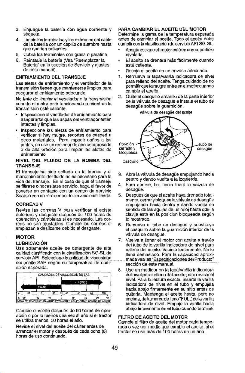
3. Enjuague la bater{a con agua corriente y
sequela.
4. LirnnpieLosterrninales y los extremos del cable
de la bateria con un cepil[o de atambre hasta
que queden brillantes.
5. Cubra los terminales con grasa o parafina.
6. Reinst_[e la bateria (Vea "Reemplazar Ia
Bateria" en la secci6n de Servicio y ajustes
de este manual).
ENFRIAMIENTO DEL TRANSEJE
Las aletas de enfriamiento y el ventilador de Ia
transmisi6ntienen que mantenerse limpiospara
asegurar el enfriamiento adecuado.
No trate de timpiar eI ventilador o la transmisi6n
cuando el motor est@funcionando o mientras Ia
transmisi6n estL• caliente.
• Inspeecione el ventilador de enfriarniento para
asegurarse que Ins aspas del ventilador esten
intactas y limpias.
• Inspeccione tas aletas de enfriamiento para
verificar si hay mugre, recortes de c_sped u
otros materiales. Para impedir dafios a Ins
juntas, no use un rociador de aire compresado
o de alta presi6n para IJmpiar Ins aletas de
enfdamiento
NIVEL DEL FLUtDO DE LA BOMBA DEL
TRANSEJE
E1 transeje ha side seUado en fa f&brica y el
mantenimiento deI fluido no es necesario para la
vida del transeje. En el caso de que el transeje
se filtrase o necesitase servicio, haga el favor de
ponerse en contacto con un centre de servicio
Sears o con un otro centro de servicio cualificado.
CORREAS V
Revise Ins correas V para verificar si existe
deterioro y desgaste despu@s de 100 horas de
operaci6n y c&mbielas si es necesario. L3s cor-
teas no son ajustables. Cambie las correas si
empiezan a deslizarse debido a! desgaste.
MOTOR
LUBRICACION
Use solamente aceite de detergente de atta
calidad clasificado con la clasfficaci6n SG-SL de
PAPA CAMBIAR EL ACEITE DEL MOTOR
Determine la gama de Ia temperatura esperada
antes de cambiar el aceite. Todo el aceite debe
cumptir con laclasificaci6n de servioio AP! SG-S L.
Asegl_rese que eltractor est@en unasuperficie
nivelada.
• El aceite se drenar& rn&s f&cilmente cuando
est6 caliente.
, Recoja el ace_te en un envase adecuado.
1. Remueva ia tapaJvarilla indicadora de nivet
para relieno del aceite. Tenga cuidado de no
permitirque ta mugre entreen el motor cuando
cambie el aceite.
2. Quite el casquillo amarillo de la parte inferior
de ta v&Ivula de desag0e e instale el tubo de
desagLie sobre faguarnici6n.
v&tvulade desag_edel aceite
Posici6rl __Tubo de
CasquilIo
3. Abra la vb,ivula de desag_e empujando hacia
dentro y dando vue!ta a la izquierda.
4. Para abrirse, tire hacia fuera la v&Ivu[a de
desagQe.
5. Despu6s de que el aceite haya drenado total-
mente, cerrarybloquee lav_lvulade desag0e
empujando hacia dentro y dando vuefta en
sentido de las agujas de un reloj hasta que Ia
clavija est& en la posici6n bloqueada segSn
Io mostrado.
6. Rernueva el tubo de desagLie y substituya
el casquillo sobre la guarniciSn inferiorde la
v_.Ivula de desagL_e.
7. Vuelva a Ilenar el motor con aceite a trav@s
del tubo de Ia varilla indicadorade niveI para
retleno del aceite. Vacielo lentamente. No Lo
llene dernasiado. Para Ia capacidad aproxi-
..servicio APLSeteccione la._;a!<!adde viscosidad madavea as"Esoec f caciones dei Producto"
de! ace_te SAE seg n su tempera urn d op r- secci6n de este manu_.i ......................................................
acton esperada. 8. Use un reed(dot en Ia tapaivariUa indicadora
CALIDAOESD_VISCOSIDADDESAE del hive[ para retleno de1aceite para revisar el
niveL Para la [ectura exacta, [nserte la variIIa
indicadora de nivel en el tubo y ernp_jela
hacia abajo firmemente en su sitio antes de
quitarla. Mantenga el aceite hasta, pero no
encima, de tamarcade []eno"FULE de tavaritla
..... indicadora de niveL Empuje la varilta hacia
abajo firmemente en el tubo cuando termine.
Cambie et aceite despu_s de 50 horas de oper-
aci6n o pot 1ornenos una vez al afio si el tractor
se utiliza menos 50 horns el ado.
Revise el nivel deLaceite deI c&rter antes de
arrancar el motor y despu@sde cada ocho (8)
horns de uso continuado.
FILTRO DE ACEITE DEL MOTOR
Cambie el filtro de aceite del motor cada tempo-
rada ovez por med[o que cambie e! acelte, si el
tractorse usa rn&s de t 00 horas en un aSo.
49
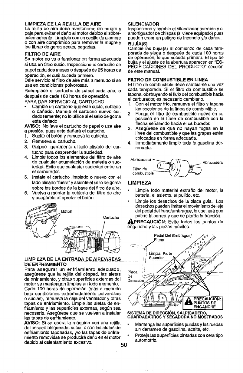
LIMPIEZA DE LA REJILLA DE AIRE
La rejilla de aire debe mantenerse sin mugre y
paja para evitar el daSo aI motor debido al sobre-
calentamiento. Limpiela con un cepil[o dealambre
o con aire compdmido para remover la mugre y
las fibras de goma secas, pegadas.
FILTRO DE AIRE
Su motor no va a funcionar en forma adecuada
si usa un filtro sucio. Inspeccione el cartucho de
papel cadados meses o despuL=sde 25 horas de
operaciSn, el cu&t suceda primero.
D_'Ie servicio al filtro de aire rods a menudo si se
usa en condiciones polvorosas.
Reemplace el cartucho de papeI cada aSo, o
despu_s de carla 100 horas de operaciSn.
PARA DAR 8ERVtCIO AL CARTUCHO
• Cambie un cartucho que est_ sucio, doblado
o dafado. Maneje el carbJchOnuevo cui-
dadosamente; no to utilice si el selIo de goma
esta daSado
AVISO: No lave el cartucho de papel o use aire
a presi6n, pues esto daSard el cartucho.
1. Suelte el botSn y remueva {a cubierta.
2. Remueva el cartucho.
3. Golpee ligeramente el lade plisado del car-
tucho para desprender la suciedad.
4. Limpie todos los elementos de! filtro de aire
de cualquier acumulaciSn de matefia o suc-
iedad. Evite que cualquier suciedad entre en
el carburador.
5. lnstale el cartucho limpiado o nuevo con el
lade p]isado "fuera" y asiente el sello de goma
sobre los berries de la base de] filtro de airs.
Vuelva a montar la cubierta del filtro de aire
y asegSrela al apretar el botSn.
SILENCIADOR
Inspeccione y cambie el silenciador corroido y el
amortiguador de chispas (si viene equipado) pues
pueden crear un peligro de incendioy!o daSos.
BUJiA(S)
Cambie {as buiia(s ) aI comienzo de cada tem-
porada de siega o despu_s de cada 100 horas
de operaci6n, Io que suceda primero. El tipo de
bujia y el ajuste de la abertura aparecen en "ES-
PECIFICACIONES DEL PIRODUCTO" secc{bn
de este manual.
FILTRO DE COMBUSTIBLE EN LINEA
El fiItro de combustibledebe cambiarse una vez
cada temporada. Si el filtro de combustible se
tapona, obstruyendo et flujo del combustible hacia
el carburador, es necesado cambiar}o.
1. Con el motor frio, remueva el filtro y tapone
las secciones de Ia Itnea de combustible.
2. Ponga el fi]tro de combustible nuevo en su
posici6n en la linea de combustib]e con la
flecha seSalando hacia el carburador.
3. Aseg0rese de que no hayan fugas en la
linea del combustible y que las grapas est_n
colocadas en forma adecuada.
4. Inmediatamente Iimpie toda la gasolina tier-
ramada.
Abrazadeta _--____.__ ,f_---.-_ Abra.zadera
combustible _-r__
LIMPIEZA
6. Limpie todo material extrafto del motor, Ia
bater{a, el asiento, el pulido, etc.
Limpie los desechos de Ia placa guia. Los
desechos pueden limitar el movimiento del eje
i Boron" deI pedal detfrenoiembrague, ioque har_,que
Cartucho patine [a correa y que se pierda la tracci6n.
_I_PRECAUCI6N: Evite todos los puntos de
enganche y ]as piezas m6viles.
PedalDetEEmbraguel/_ _ _>.
LIMPIEZA DE LA ENTRADA DE AtRE/AREAS t SUlked°l=___'//_
DEENFRIAMIENTO ................................................................................' i_ 1_7_//_ _._ "
Para asegurar un enfriamiento adecuado _, : _./_--_.J __
I I s , . ' Haca .... _ I
aseg_rese que a rejilla del c6sped, a aletas r_, __>_-_
de enfriamiento, y otrassuperficies externas deI D_recci6n__._,,_ __k "t
motor se mantengan mpias en todo memento ,_,{,'7-_,_,_ _ i_-_\
Cada t00 horas de operaci6n (m&s a menudo ./_<J_ _._ J'/_" _ -'-_,
bajo condiciones extremadamente polvorosas /_(_/_ =_=_,// 1
o sucias) rernueva ta caja del ventilador y otras ,. _ "_._:_ _'__.___RECAU'C_I6 N: I
tapas de 'enfriamiento. Limpie tas aletas de en- _'._>-. _._1 _,_ EPUNTOSD_'JA : :_--. ---_-_.-,
friamiento y tas superficies externas, seg_[n sea : _ I NGANCHE J
necesario. Aseg6rese que se vuelvan a instalar SfSTEMADIEDIRECCt6N,SALPICADERO,
las tapas de enfdamiento. GUARDABARROS Y SEGADORA NO MOSTRADO8
AVISO: Si se opera la mdquina con una rejilla , Mantenga Ias superficies pulidasy lasruedas
del c_sped bloqueada, sucia,o con las alefas de sin derrames de gasolina, aceite, etc.
enfriamiento taponadas, y/o las tapas de enfria- • Proteja las superficies pintadas concera ripe
miento remov]das se producir& daSo en el motor automotdz.
debido at calentamiento excesivo. 50
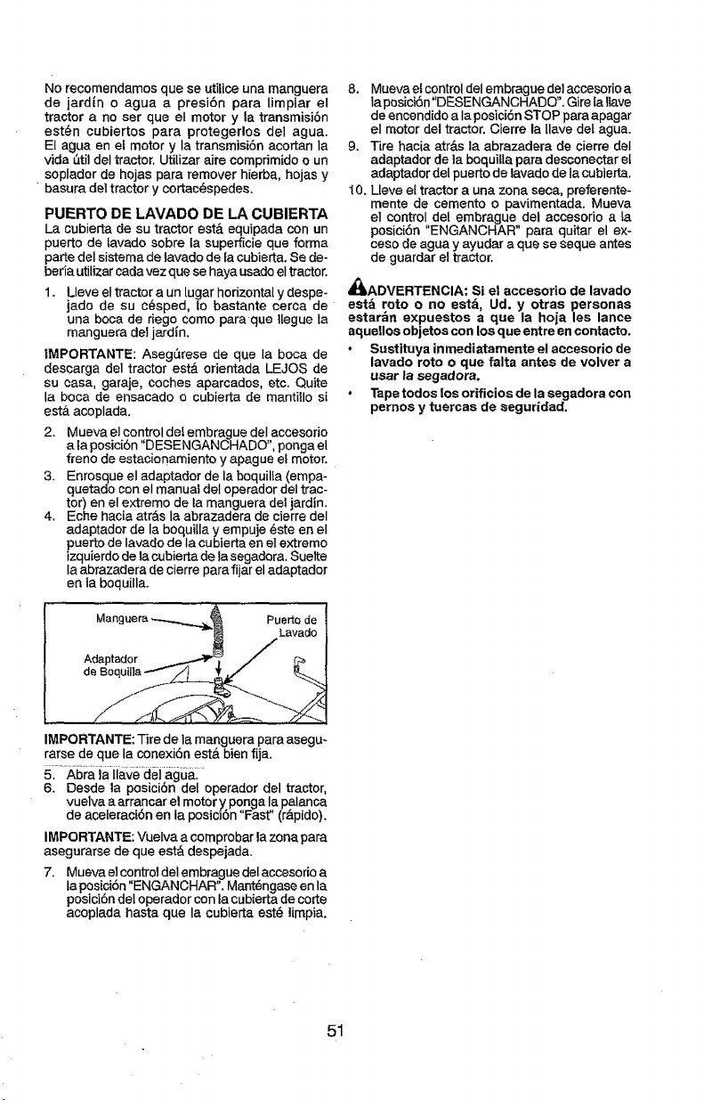
No recomendamos que se utilice una manguera
de jard{n o agua a presi6n para limpiar el
tractor a no set que el motor y {a transmisi6n
est6n cubiertos para protegerlos del agua.
El agua en el motor y Ia transmisi6n acortan ia
vida 5til deI tractor. Utilizar aire comprimido o un
soplador de hojas para remover hierba, hojas y
basura del tractor y cortac(_spedes.
PUERTO DE LAVADO DE LA CUBIERTA
La cubierta de su tractor est_ equipada con un
puerto de Lavado sobre la super_cie que forma
parts del sistema de lavado de la cubierta. Se de-
bsria utilizar cadavez que se haya usado el tractor.
1. Lleve el tractor a un [ugar horizontal y despe-
jado de su c6sped, lo bastante cerca de
una boca de riego como para que llegue [a
manguera del jardln.
tMPORTANTE: Aseg_rese de que la boca de
descarga del tractor est& orientada LEJOS de
su oasa, garaje, coches aparcados, ete, Quite
la boca de ensacado o cubierta de mantillo si
est_ acoplada.
2. Mueva el control deLembrague del accesorio
a fa posici6n"DESENGANCHADO", ponga el
treno de estacionamiento y apague el motor.
3. Enrosque el adaptador de la boquilla (empa-
quetado con el manual deI operador deI trac-
tor) en el extremo de tamanguera del jardin.
4. Echo hacia atr&s la abrazadera de cierre del
adaptador de la boquiUa y empuje (_steen el
puerto de Iavado de Ia cubierta en el extremo
izquierdode lacubierta de la segadora. Suelte
Ia abrazadera de cierre parafijar el adaptador
en la boquilla.
Puerto de
Lavado
8. Mueva el control del embrague del accesorio a
Iaposici6n"DESENGANCHADO", Gire la Ilave
de encendido a Ia posici6nSTOP paraapagar
el motor del tractor. Cierre la llave dot agua.
9. Tire hacia atr&s la abrazadera de cierre del
adaptador de la boquit[a para desconectar et
adaptador del puerto de lavado de Ia cubierta.
I0. Lleve el tractor a una zona seca, preferente-
monte de cemento o pavimentada. Mueva
el control del embrague del acc_sorio a ta
posJci6n"ENGANCHAR" para quitar el ex-
ceso de agua y ayudar a que se seque antes
de guardar el tractor.
_ADVERTENCIA: Si el accesorio de lavado
est& roto o no est,, Ud. y otras personas
estar_n expuestos a que la hoja los lance
aqueUos objetos con los que entre en contacto.
• Sustituya inmediatarnente el aecesorio de
lavado roto o que falta antes de volver a
usar la segadora.
• Tapetodos los orificios de la segadora con
pernos y tuercas de seguridad.
IMPORTANTE: Tire de la manguera para asegu-
rarse de que la conexi6n est& bien fija.
5. Abra la Ilave del agua.
6. Desde la posici6n del operador del tractor,
vuelva a arrancar el motor y ponga la palanca
de aceleraoi6n en la posici6n "Fast" (r&pido).
IMPORTANTE; Vuelva a cornprobar la zona para
asegurarse de que est& despejada.
7. Mueva el control del embrague del accesorio a
la posici6n"ENGANCHAR". Mant_ngase en la
posici6ndel operador con la cubierta de corte
acoplada hasta que la cubierta est_ limpia.
51
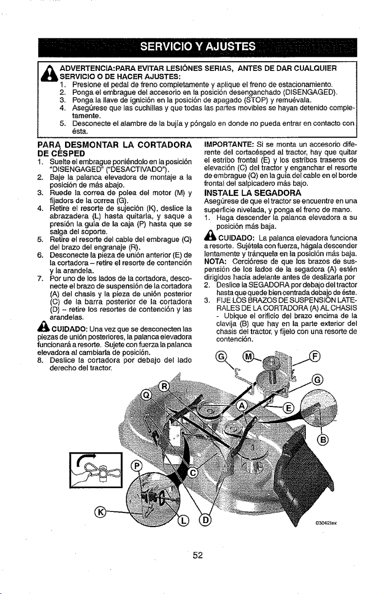
A DVERTENCIA:PARA EVITAR LESt6NES SERIAS, ANTES DE DAR CUALQUIER
SERVIC]O O DE HACER AJUSTES:
1. Presione el pedal de freno cornpletarnente y aplique el freno de estacionarniento.
2. Ponga at embrague del accesodo en Ia posicion desenganchado (DISENGAGED).
3. Ponga la llave de ignici6n en la posici6nde apagado (STOP) y remu@vala.
4. AsegOrese que las cuchillas y que todas [as partes movibles se hayan detenido cornple-
tarnente.
5. Desconecte el atarnbre de la bujfa y p6ngalo en donde no pueda entrar en contacto con
@sta.
PARA DESMONTAR LA CORTADORA
1. Suelte el ernbrague poni_ndoJo en ta posici6n
"DISENGAGED" ("DESACTIVADO").
2. Baje la palanca elevadora de montaje a la
posici6n de rn&s abajo.
3. Ruede ]a correa de polea dat motor (M) y
fijadors de la correa (G).
4. Retire el resorte de sujecibn (K), deslice ta
abrazadera (L) hasta quitarla, y saque a
presibn la guia de la caja (P) hasta que se
salga del soporte.
5. Retire el resorte deI cable del ernbrague (Q)
deI brazo deI engranaje (R).
6. Desconecte la pieza de uniSn anterior (E) de
la cortadora - retire el resorte de contencibn
y la arandela.
7. Pot uno de los lades de ta cortadora, desco-
necte el brazo de suspensi6n de la cortadora
(A) del chasis y la pieza de uni6n posterior
(C) de Ia barra posterior de la cortadora
(D) - retire los resortes de contenciSn y tas
arandelas,
_k CUIDADO: Una vez que se desconecten Jas
piezas de uni6n posteriores, la palanca elevadora
funcionar& a resorte. Sujete con fuerza ta palanca
atevadora at carnbiarlade posici6n.
8. Deslice ta cortadora por debajo del Iado
derecho det tractor.
IMPORTANTE: Si se monta un accesorio dife-
rente del cortac_sped at tractor, hay que quitar
et estribo frontal (E) y los estribos traseros de
elevaciSn (C) del tractor y enganchar el resorte
de embrague (Q) en ]a guia deI cable en el horde
frontal deI salpicadero rn&s bajo.
INSTALE LA SEGADORA
Aseg_rese de que el tractor se encuentre en una
superficie nivelada, y ponga el freno de mano.
1. Haga descender la palanca elevadora a su
_lPOSiCiSn rn&s baja.
CUIDADO: La palanca elevadora funciona
a resorte. Suj@telacon fuerza, h&gala descender
]entamente y tr&nquela en la posici6n rn&s baja.
NOTA: Cerci6rese de que los brazes de sus-
pensiSn de los lados de ]a segadora (A) est6n
didgidos hacia adelante antes de deslizarla por
2. Deslice ]a SEGADORA pot debajo del tractor
hasta que quede biencentrada debajp de 6ste.
3. FIJE LOS BRAZOS DE SUSPENSION LATE-
RALES DE LA CORTADORA (A)AL CHAStS
- Ubique el orificio del brazo encima de la
clavija (13)que hay en la parte exterior del
chasis deI tractor, y fijelo con una resorte de
contenci6n.
®
03042te_
52
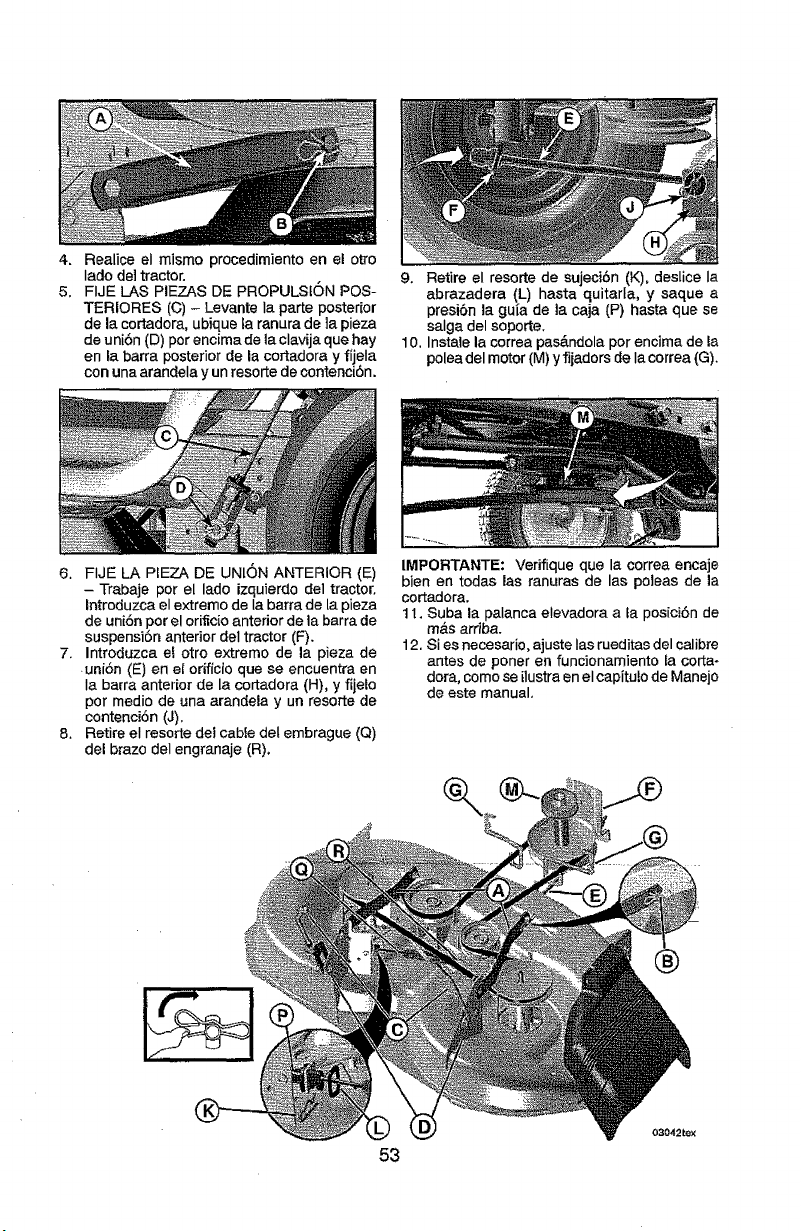
4-,
5.
Realice el mismo procedimiento en el otto
lade del tractor.
FIJE LAS PIEZAS DE PROPULSK_N POS-
TERIORES (C) - Levante Ia parte posterior
de la cortadora, ubique la ranura de la pieza
de uni6n (D) per encima de la clavija que hay
en la barra posterior de la cortadora y fijela
con una aranclela y un resorte de contenciSn.
9. Retire el resorte de sujeci6n (K), deslice Ia
abrazadera (L) hasta quitarfa, y saque a
presi6n la gu[a de la caja (P) hasta que se
salga del soporte.
10. Instale la correa pas&ndola per encima de la
polea del motor (M) y fijadors de Ia correa (G).
6. FIJE LA PIEZA DE UNION ANTERIOR (E)
- Trabaje per el lade izquierdo del tractor.
Introduzca el extreme de Ia barra de la pieza
de uni6n per el orificio anterior de la barra de
suspensi6n anterior del tractor (F).
7. Introduzca et otto extreme de la pieza de
uni6n (E) en el odficio que se encuentra en
Ia barra anterior de la cortadora (H), y fijelo
per medio de una arandela y un resorte de
contenci6n (J).
8. Retire el resorte del cabte del embrague (Q)
del braze del engranaje (R).
IMPORTANTE: Verifique que la correa encaje
bien en todas las ranuras de las poleas de la
cortadora.
11. Suba la palanca elevadora a la posici6n de
m_tsarriba.
12. Si es necesario, ajuste Ias rueditas del calibre
antes de poner en funcionamiento fa corta-
dora, come se ilustra en el capitulo de Manejo
de este manual.
53
03042_X
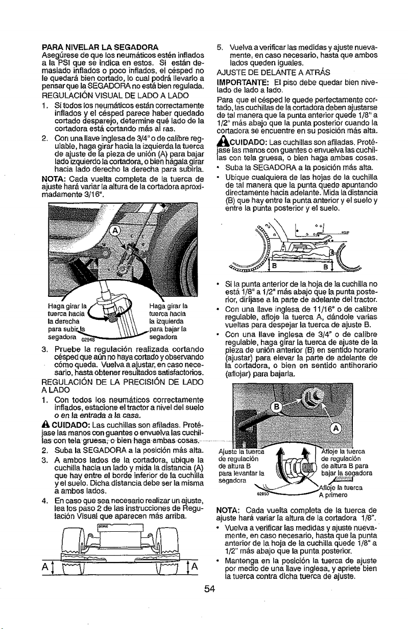
PARA NIVELAR LA SEGADORA
Aseg0rese de que los neum_,ticosest_n inflados
ala PSi que se indice en estos. Si est&n de-
masiado inflados o poco inflados, el c6sped no
le quedar_, bien cortado, Io cual podr& Ilevarlo a
pensarque la SEGADOP_ no estA bien regulada.
REGULACION VISUAL DE LADO A LADO
1. Si todos |os neum&ticos est_n correctamente
inflados y el c_sped parece haber quedado
cortado desparejo, determine qu_ lado de la
cortadora est& cortando m&s aI ras.
2. Con una Ilave inglesade 3/4"o de calibre reg-
ulable, haga girar hacia fa izquierda la tuerca
de ajuste de la pieza de uni6n (A) para bajar
ledo izquierdo la cortadora, o bien h&gala girar
hacia Iado derecho la derecha para subirla.
NOTA: Cada vuelte complete de Ia tuerca de
ajuste hat& variar la alture de la cortadora aproxi-
madamente 3/16",
Hagagirar la HagagirarIa o
tuerca hacia! tuerca hacia
la derecha la izquierda
.pare bajarla
segadora segadora "
3. Pruebe la regulaci6n realizada cortando
c6spedqueadn no hayacorlado y observando
c6mo queda. Vue]va a ajustar, en caso nece-
sario, hasteobtener resultados satisfactorios.
REGULACION DE LA PRECISION DE LADO
A I.ADO
1, Con todos los neum&ticos correctamente
inflados, estacione el tractor a nivel del suelo
o en la eatrada a _acasa.
_t, CUIDADO: Las cuchi[Iasson afiladas. Protb-
ase lasmanos conguanteso envuelvalas cuchil-
ascon tela-gruesarobien haga ambas coses. .....................
2, Suba la SEGADORA ala posici6n m&s alta.
3. A embos lados de la cortadora, ubique la
cuchitla hacia un lado y mida la distancia (A)
que hay entre el horde inferior de la cuchi!la
y el suelo. Dicha distancia debe ser la misma
a ambos lados.
4, En caso que sea necesado realizar un ajuste,
lea los paso 2 de las instruccionesde Regu-
laci6n Visual que aparecen mAs ardba.
5. Vuelva a verificar Ias medidas y ajuste nueva-
mente, en caso necesario, hasta que ambos
Iados queden iguales.
AJUSTE DE DELANTE A ATRAS
IMPORTANTE: El piso debe quedar bien nive-
lado de lado a lado.
Pare que el c@speclle quede perfectamentecor-
tado, tascuchillas de ta cortadora deben aiustarse
de tel manera que la punta anterior quede I/8" a
1/2" m&s abajo que la punta posterior cuando la
cortadora se encuentre en su posiciSn m&s atta,
j_OUIDADO: Las cuchillas son afiladas. Prot6-
ase las manos con guantes o envuelve tascuchit-
Ias con te]a gruesa, o bien haga ambas cosas,
• Suba la SEGADORA ala posici6n m_.salta.
• Ubique cuelquiera de las hojas de la cuchilla
de tel manera que la punta quede apuntando
directamente hacia adelante, Mida la distancia
(B) que hay entre la punta anterior y el suelo y
entre la punta posterior y el suelo.
Si la punta anterior de Ia hoja de ]a cuchiila no
estA 1/8" a 1t2" m&s abajo que la punta poste-
rior, dirijase ala parte de adelante del tractor.
Con una Ifave inglesa de t 1/16" o de calibre
regulable, afloje Ia tuerca A, d&ndole varies
vueltas para despejar la tuerca de ajuste B.
Con una Ilave inglesa de 3/4" o de calibre
regulable, haga girar fa tuerca de ajuste de la
pieza de uni6n anterior (t3)en sentido horatio
(ajustar) pare elevar la parle de adelante de
la cortadora, o bien en sentido antihorario
(afIojar) pare bajarla,
Ajuste Ia tuerca
de regulaci6n de regulacibn
de altura B de altura B para
para levantar Ia
segadora
NOTA: Cada vuelta complete de la tuerca de
ajuste har& variar la altura de la corladora 1/8".
. Vuelva averificar las medides y ajuste nueva-
mente, en caso necesario, haste queta punta
anterior de la hoja de la cuchilla quede 1/8" a
1/2" m&s abajo que la punta posterior.
• Mantenga en la posici6n Ia tuerca de ajuste
por medio de una ltave inglesa, y apriete bien
la tuerca contra dicha tuerca de ajuste.
54
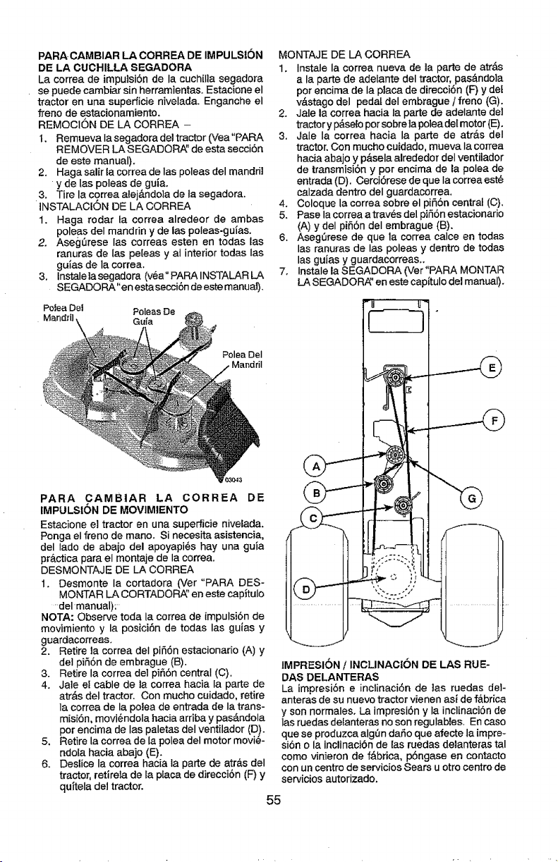
PARA CAMBIAR LA CORREA DE IMPULSI6N
DE LA CUCHILLA SEGADORA
La correa de impulsi6n de la cuchiI]a segadora
se puede cambiar sin herramientas+ Estacione el
tractor en una superficie nivelada+ Enganche el
freno de estacionamiento.
REMOCION DE LA CORREA -
I. Remueva Ia segadora del tractor (Vea "PARA
REMOVER LA SEGADOR/_' de esta secci6n
de este manual).
2. Haga salir la correa de las poleas del mandril
y de Ias poleas de guia.
3. Tire la cgrrea alej&ndo]a de la segadora,
iNSTALACION DE LA CORREA
1. Haga rodar ia correa alredeor de ambas
poleas deI mandrin y de las poleas-gui'as+
2+ Aseg0rese Ias correas esten en todas las
ranuras de Ias pe[eas y at interior todas Ias
gu_as de la correa.
3. lnstalelasegadora (v_a"PARAINSTALARLA
SEGADORA"en esta secci6n de este manuaJ).
Poiea Del Poleas De
Mandril Gufa
Polea DeI
PARA CAMBIAR LA CORREA DE
IMPULSION DE MOVIM1ENTO
Estacione e] tractor en una superficie nivelada+
Ponga el freno de mano. Si necesitaasistencia,
del Iado de abajo del apoyapi@shay una guia
pr_.cticapara el montaje de la correa.
DESMONTAJE DE LA CORREA
1. Desmonte la cortadora (Ver "PARA DES-
MONTAR LA CORTADORh:' en este capitulo
-del manual):
NOTA: Observe toda la correa de impulsi6n de
movimiento y la posici6n de todas las guias y
guardacorreas+
2. Retire la correa deI pi56n estacionano (A) y
de] pi56n de embrague (B),
3. Retire la correa del pi_6n central (C).
4. Jaie el cable de la correa hacia la parte de
atr&s deI tractor, Con mucho cuidado, retire
la correa de la polea de entrada de Ia trans-
misi6n, movi_ndola hacia arriba y pasAndola
por encima de Ias paletas del ventilador (D)+
5+ Retire la correa de [a polea del motor movi@-
ndola hacia abajo (E).
6. Deslice Ia correa hacia la parte de atr&s del
tractor, retirela de ta ptaca de direcci6n (F) y
quTteladel tractor.
MONTAJE DE LA CORREA
1. Instale la eorrea nueva de la parte de atr&s
a la parte de adefante del tractor, pas_ndola
pot encima de Ia placa de direcci6n (F) y deL
v&stago del pedal del embrague / freno (G).
2. Jale la correa hacia la parte de adelante del
tractor y I_selo per sobre ta poleadel motor (E).
3, Jale Ia correa hacia la parte de atr_.s deI
tractor. Con mucho cuidado, mueva la correa
hacia abajo y p&sela alrededor del ventilador
de transmisi6n y por encima de la polea de
entrada (D), Cerci6rese de que Ia correaest_
calzada dentro del guardacorrea,
4. Coloque la correa sobre el pi56n central (C)+
5+ Paso la correa atrav_s del pi56n estacionario
(A) y del pi56n deI embrague (B).
6. Aseg0rese de que la correa calce en todas
las ranuras de Ias poleas y dentro de todas
las guias y guardacorreas_
7. Instale la SEGADORA (Ver '+PARAMONTAR
LA SEGADORA_'en este capitulo del manual).
IMPRESION / INCLINAC|ON DE LAS RUE-
DAS DELANTERAS
La impresi6n e inclinaciSn de 3as ruedas del-
anteras de su nuevo tractor vienen asi dof&brica
y son normaleso La impresi6n y la inclinacionde
Ias ruedas delanteras no son regulables. En caso
que se produzca alg0n daSo que afecte la impre+
si6n o la inclinacibn de Easruedas delanteras tal
como vinieron de fAbrica, p6ngase en contacto
con un centro de servicios Sears u otro centre do
servicios autorizado.
55
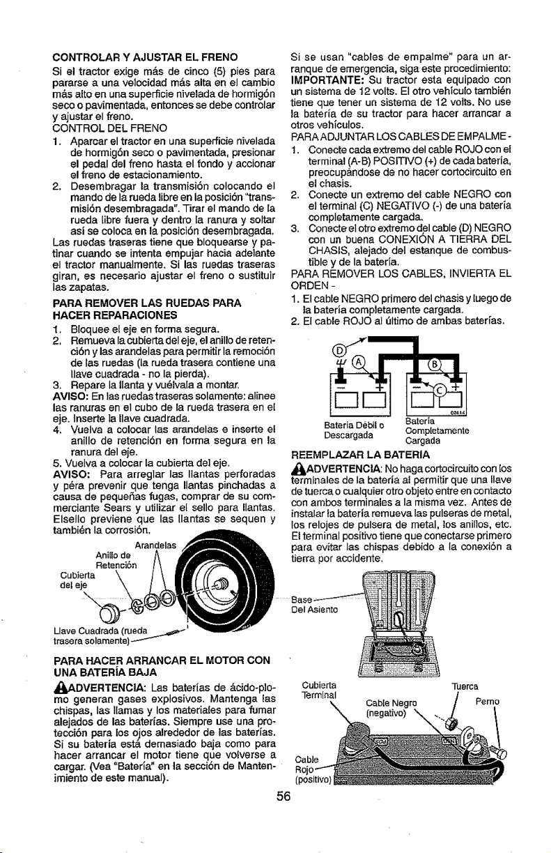
CONTROLAR Y AJUSTAR EL FRENO
Si el tractor exige m_.s de cinco (5) pies para
pararse a una velocidad m&s alta en el cambio
m&s alto en una superficie nivelada de hormig6n
seco o pavimentada, entonces se debe controlar
y ajustar el freno.
CONTROL DEL FRENO
1. Aparcar el tractor en una superPicie nivelada
de hormigdn seco o pavimentada, presionar
el pedal del freno hast_ el fondo y accionar
el freno de estacionamiento.
2. Desembragar la transmisi6n colocando el
mando de la rueda tibreen la posicidn "trans-
misi6n desembragada". -I-irar el mando de la
rueda Iibre fuera y dentro la ranura y soltar
asi se coloca en la posici6n desembragada.
Las ruedas traseras tiene que bloquearse y pa-
tinar cuando se intenta empujar hacia adelante
el tractor manualmente. Si las ruedas traseras
giran, es necesario ajustar el freno o sustituir
las zapatas.
PARA REMOVER LAS RUEDAS PARA
HACER REPARACIONES
1. Bloquee el eje en forma segura.
2, Remueva lacubiertadel eje, el anillo de reten-
cidn y las arandelas para permitir Ia remocibn
de !as ruedas (la rueda trasera contiene una
llave euadrada - no la pierda).
3. Repare Ia Ilanta y vu_tva[a a montar.
AVISO: En las ruedas traseras solamente: atinee
las ranuras en eI cube de la rueda trasera en e[
eje. Inserte la tlave cuadrada.
4. Vuelva a colocar Ias arandelas e inserte et
anilIo de retencidn en forma segura en la
ranura del eje.
5. Vuelva a colocar ta cubierta de1eje.
AVISO: Para arreglar Ias Ilantas perforadas
y p_ra prevenir que tenga Ilantas pinchadas a
causa de pequeSas fugas, comprar de su com-
merciante Sears y utilizar et sello para llantas.
Elsello previene que las Ilantas se sequen y
tambi@n la corrosidn.
Arandelas
Ani[[o de
Retencidn
Cubierta
del eje
Llave Cuadrada (rueda =_._._=_
trasera solamente)
Si se usan "cables de empalme" para un ar-
ranque de emergencia, siga este procedimiento:
IMPORTANTE: Su tractor esta equipado con
un sistema de t2 volts. El otro vehiculo tambi@n
tiene que tener un sistema de 12 volts. No use
la bateria de su tractor para hacer arrancar a
otros vehiculos.
PARAADJUNTAR LOS CABLES DE EMPALME-
1. Conecte cada extreme del cable ROJO con el
terminal (A-B) POSITIVe (+) de cada bateria,
preocup&ndose de no hacer cortocircuitoen
el chasis.
2. Conecte un extreme del cable NEGRO con
el terminal (C) NEGATtVO (-) de una bateria
completamente cargada.
3. Conecte eI otro extreme d el cable (D) NEGRO
con un buena CONEXION A TIERRA DEL
CHASIS, atejado deI estanque de combus-
tible y de la bateria.
PARA REMOVER LOS CABLES, INVIERTA EL
ORDEN -
1. El cable NEGRO primero del chasis y luego de
la bateria completamente cargada.
2. El cable ROJO aI _Itimo de ambas bateHas.
BateriaDebii o 8aterta
Descargada Corop[etamente
Cargada
REEMPLAZAR LA BATERIA
_ADVERTENCIA: No hagacortocircuitocon los
terminales de Ia bateria at permitir que una Ilave
de tuerca o cualquier otro objetoentre en contacto
con ambos terminales a Ia misma vez. Antes de
instalar ta bateria remueva Easpulseras de metal,
los relojes de pulsera de metal, los anillos, etc.
Elterminal positive tiene que conectarse pdmero
para evitar Ias chispas debido a la conexiSn a
tierra per accidente.
DeI Asiento
PARA HACER ARRANCAR EL MOTOR CON
UNA BATERiA BAJA
_pADVERTENC]A: Las baterias de _.cido-plo- Oubierta
me generan gases explosives. Mantenga las Terminal
chispas, las llamas y los materiates para fumar
alejados de las baterias. Siempre use una pro-
teccibn para los ojos alrededor de las bater[as.
Si su bateria est,. demasiado baja come para
hacer arrancar el motor tiene que votverse a Cable
cargar. (Vea "Bateda" en la seccibn de Manten-
imiento de este manual). (positive)
56
Cabte Negro
(negative)
ruerc_
Perno
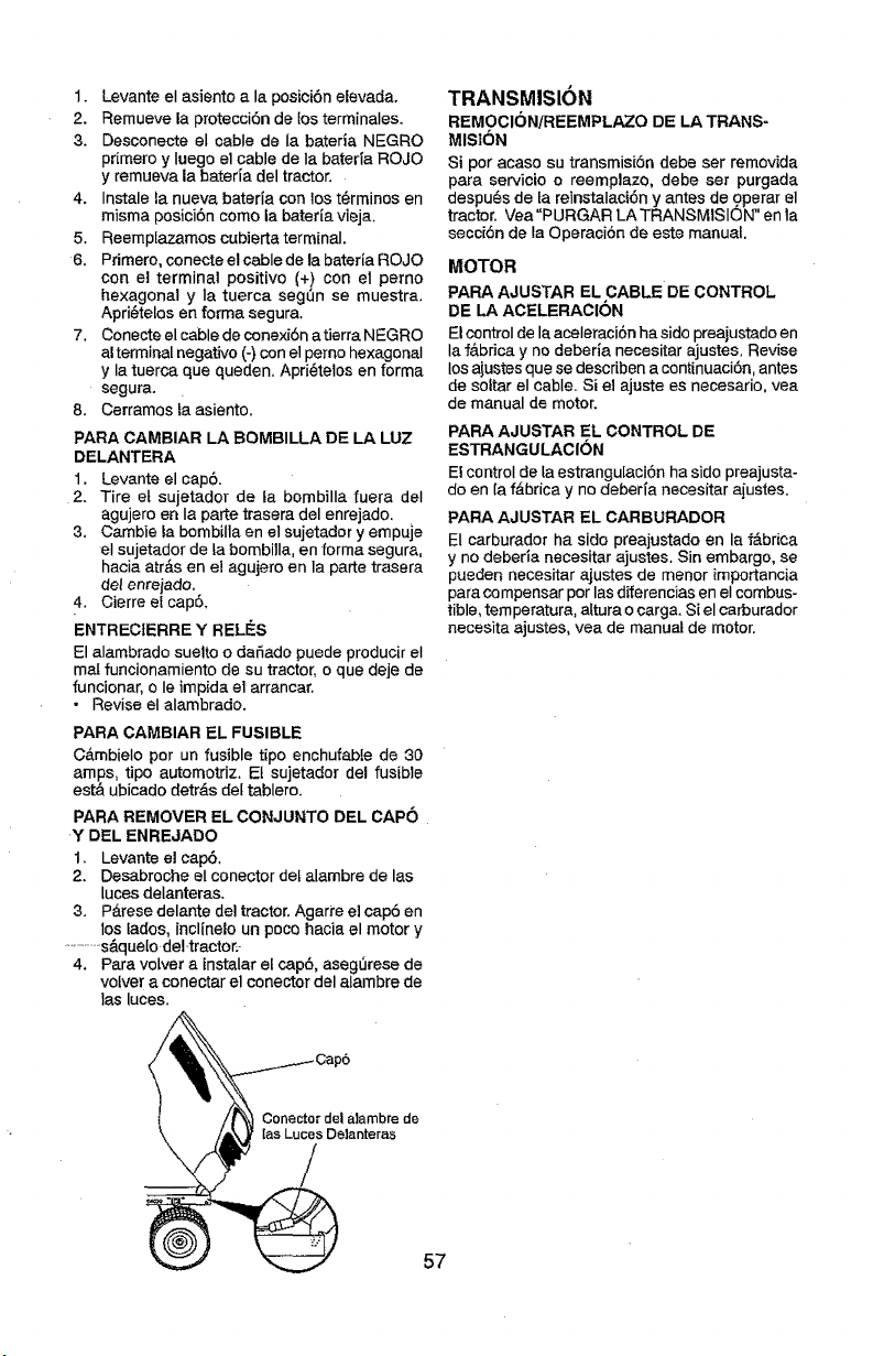
1. Levante el asiento a la posiei6n elevada,
2. Remueve la protecci6n de los terminales.
3, Desconecte el cable de Ia bateria NEGRO
primero y luego el cable de la bateria ROJO
y remueva la bateria del tractor,
4, Ins'tale la nueva bateria con los t6rminos en
misma posici6n como la bateria vieja,
5. Reemplazamos cubierta terminal,
6. Primero, conecte el cable de la bateria ROJO
con el terminal positivo (+) con el pemo
hexagonal y la tuerca seg_n se muestra,
Apri6telos en forma segura.
7. Conecte el cable de conexi6natierra NEGRO
alterminal negative (-) con el perno hexagonal
y la tuerca que queden. Apri_telos en forma
segura,
8. Cerramostaasiento.
PARA CAMBIAR LA BOMBILLA DE LA LUZ
DELANTERA
1. Levante el cap6.
2. Tire el sujetador de ta bombilla fuera deI
agujero en la parle trasera del enrejado.
3. Cambie la bombilla en el sujetador y empuje
el sujetador de ta bombilla, en forma segura,
hacia atr&s en el agujero en la parte trasera
del enrejado.
4, Cierre etcap6,
ENTRECIERRE Y RELIES
El alambrado suelto o dafiado puede producir el
mal funcionamiento de su tractor, o que deje de
funcionar, o le impida el arrancar,
* Revise el alambrado.
PARA CAMBIAR EL FUSIBLE
C&mbielo por un fusible tipo enchufable de 30
amps, tipo automotriz. El sujetador del fusible
est& ubicado detr&s det tablero.
PARA REMOVER EL CONJUNTO DEL CAP6
Y DEL ENREJADO
1. Levante el cap6.
2. Desabroche el coneotordef alambre de las
luces delanteras,
3. P_.rese delante del tractor. Agarre el cap6 en
los lades, inclinelo un poco hacia el motor y
...............s&quelo del-tractor,-
4. Para vo[ver a instalar el cap5, aseg0rese de
volver a conec_ar el conector del atambre de
las luces.
TRANSMISION
REMOCIONiREEMPLAZO DE LA TRANS-
MISI6N
Si por acaso su transmisi6n debe ser removida
para servicio o reemplazo, debe set purgada
despu_s de ta reinstalaci6n y antes de operar el
tractor. Vea "PURGAR LATRANSMISION" enla
secci6n de la Operaci6n de este manual.
MOTOR
PARA AJUSTAR EL CABLE DE CONTROL
DE LA ACELERACION
Elcontrol de la aceleraci6n ha sido preajustado en
la f&brica y no deberia necesitar ajustes. Revise
los ajustes que se describen a continuaci6n, antes
de sottar el cable. Si el ajuste es necesario, vea
de manual de motor.
PARA AJUSTAR EL CONTROL DE
ESTRANGULACION
Elcontrol de la estrangulaci6n ha side preajusta-
do en la f&brica y no deberia necesitar aiustes.
PARA AJUSTAR EL CARBURADOR
El carburador ha sido preajustado en la f_.briea
y no deberia necesitar ajustes. Sin embargo, se
pueden necesitar ajustes de menor importancia
para compensar por las diferencias en el combus-
tible, temperatura, altura o carga. Si el carburador
necesita ajustes, vea de manual de motor.
Conecto[ del alambre de
[as Luces Delanteras
57

Inmediatamente prepare su tractor para el alma-
cenamiento aI final de la temporada o si el tractor
no se va a usar pot 30 dias o m&s.
_bADVERTENOIA: Nunca almacene el tractor
con gasolina en el estanque dentro de un edificio
en donde los gases pueden alcanzar una llama
expuesta o una chispa. Permita que el motor se
enfrie antes de almacenar[o en cualquier recinto
privado,
TRACTOR
Cuando el tractor se va a almacenar pot cierto
periodo de tiempo, limpieIa cuidadosamente,
quite toda Ia mugre, la grasa, las hojas, etc.
Gu_.rdela en una &rea Iimpla y seca.
t. Limpie todo el tractor (vea "LIMPtEZ_' en la
seccibn de Mantenimiento en este manual).
2. Inspeccione y cambie tascorreas, si es nece-
sario (vea las instrucciones para el cambio de
las correas en la secci6n de Servicio y Ajustes
de este manual).
3. Lubriquelo, segSn se muestra en la secci6n
de Mantenimiento de este manual.
4. Asegflrese quetodas ]astuercas, los pernos y
los tornillos est_n sujetados en forma segura,
Inspeccione Ias partes movtbles para verificar
si hay dafio, rotura o desgaste. C&mbielas si
es necesario.
5. Retoque todas superficies pintadas oxidadas
o picadas; aplique lija antes de pintar.
BATERIA
• Cargue la bateda completamente antes de
guardarla.
• Despu_s de cierto periodo de tiempo en alma-
cenamiento, la bateda puede necesitar volver
a cargarse.
• Para ayudar a evitar la corrosi6n y Ias fugas
de potencia durante largos periodos de alma-
cenamiento, se deben desconectar los cables
de la bateria y se debe Limpiar cuidadosamen-
te (yea "PARA LIMPIAR LA BATERIA Y LOS
TERMINALES" en Ia secci6n de Mantenimien-
tode este manual).
• Despu6s de limpiarla, deje los cables desco-
nectados y p6ngalos en donde no puedan
• Vaciar el dep6sito de[ carburante poniendo en
marcha el motor y dej&ndolo funcionar hasta
que el carburante termine el carburador est_
vacio.
• Nunca use los productos para limpieza del
carburador o deI motor en el estanque de
combustible pues se pueden producir dafios
permanentes,
• Use combustible nuevo la pr6xima temporada,
AVlSO: El estabilizador de combustible es una
altemativa aceptable para reducir a un minimo
la formaci6n de dep6sitos de goma en el com-
bustible durante el periodo de almacenamiento.
Agregue estabilizador a la gasolina en el es-
tanque de combustible o en el envase para el
almacenamiento. Siempre siga la proporci6nde
mezcla que se encuentra en el envase del estabi-
lizador. Haga funcionar el motor por Io menos 10
minutos despu_s de agregar el estabilizador, para
permitir que _ste []egueal carburador. No vaciar la
gaselina del estanque de gasolina y el carburador
si se est& usando estabilizador de combustible.
ACEITE DEL MOTOR
Drene el aceite (con el motor caliente) y c&mbielo
con aceite de motor limpio. (Vea "MOTOR" en
la secci6n de Mantenimiento" de este manual.)
CILINDRO(S)
1. Remueva la(s) bujia(s).
2. Vacie una onza de aceite a trav_s deI
agujero(s) de la bujia en el cilindro(s).
3. Gire Ia tlave de ignici6na la posici6n de 'Ar-
ranque" (Start), por unos cuantos segundos
para distribuir el aceite.
4. Cambie por bujia(s) nueva(s).
OTROS
• No guarde Ia gasolina de una temporada a la
otra.
• Oambie el envase de Ia gasolina si se emp-
ieza a oxidar. La oxidaci6n y/o Ia mugre en su
gasolina producir&n problemas.
• Si es posible,guarde su unidad en un recinto
cerrado y cSbrala para protegerla contra ef
polvo y la mugre.
• Cubra su unidad con un forro protector ad-
.................................entrar._en .contacto conJos term na es.de, a ....................ecuad_.que_o.o. [etenga la h#fnedad._Ng__use.......
bateria.
• Si se remueve la bateria deI tractor para el
almacenamiento, no la guarde directamente
sobre concreto o sobre superficies ht_medas.
MOTOR
SISTEMA DE COMBUSTIBLE
IMPORTANTE: Es important evitar que se
forman depositos de goma en partes funda-
mentales del sistema de combus-tible tales
como et carburador, el fittro del combustible,
la manguera del combustibles mezclados con
alcohol (conocido como gasohoI o que tienen
etanot o metanol) pueden atraer humedad, 1o
que conduce a Ia separacibn y a la formaci6n
de acudos durante elaimacenamiento. La gaso-
lina acidica puede dafiar el sistema de combus-
tible de un motor durante el periodo de almace-
namiento. 58
pI_tstico. El pl&stico no puede respirar, Io que
permite la formaci6n de condensaci6n, Io que
producir&la oxidaci6n de su unidad.
IMPORTANTE: Nunca cubra el tractor mientras
el motor y las areas de escape todavia estan
calientes,
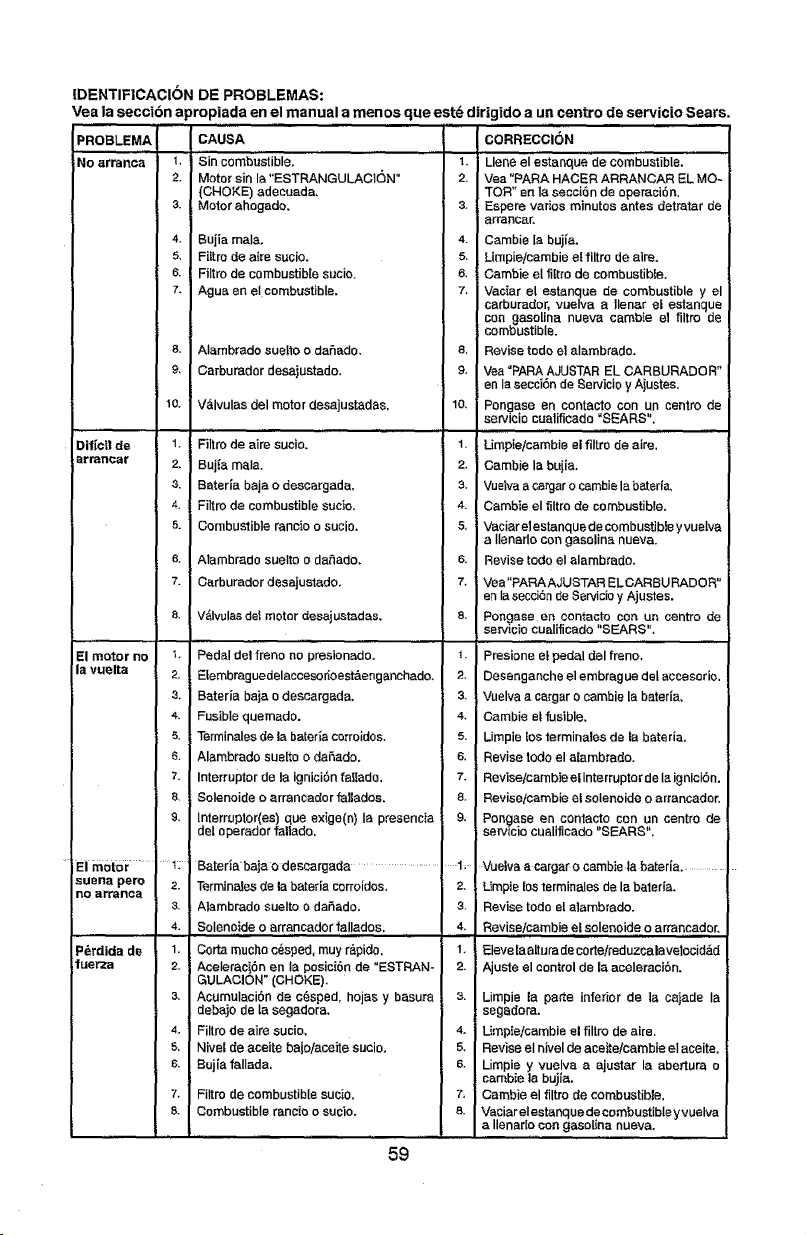
IDENTIFICACION DE PROBLEMAS:
Vea Áaseccibn apropiada en el manual a menos que est_ dirigido a un centre de servicio Sears.
PROBLEMA CAUSA
No arranca 1, Sin combustible,
2. Motor sin la"ESTRANGULACI6N"
(CHOKE) adeeuada,
3. Motor ahogado,
Dif[cn de
_lrraTlear
4. Buiia male,
5, Fittro de aim sucio,
6. Filtro de combustible sucio.
7. Ague en elcombustible,
& Alambrado suelto o dafado,
9, Carburador desajustado.
10, V&lvulas del motor desajustadas.
,,,,, _,,,,_,,,,,,,,,,,_........
1, Filtro de airs sucio,
2, Buj{a mala.
3. Bateria baja o descargada.
4. Filtro de combustible sucio.
5. Combustible rancio o sucio,
& Alambrado suelto o dafiado,
7. Carburador desajustado,
8.
El motor no t.
la vuelta 2.
3,
4,
5.
6.
7.
&
&
Eim0tor ......... 1;
suena pete 2.
Re aFranca
3.
P_rdida de 1.
luerza 2,
V_lvulas del motor desajustadas,
, ,,,,,,,L
Pedal del freno no presionado,
Efembrag uedelacceso rioest&en ganchado,
Bateria baja o descargada,
Fusible quernado.
Terminales de Iabateda corroidos,
Alambrado sue[to o daaado,
Interrupter de la ignici6n fallado.
SoIenoide o arrancador fallados,
lnterruptor(es) que exige(n) Ia presencia i
deI operador fallado,
Bateda'baja o deseargada .....................
TerminaJesde la bateria corroidos.
Alambrado suelto o dahado.
Solenotde o arrancador fallados.
Corta macho c_sped, muy r_,pido.
Aceleraci6n en lapesici6n de "ESTRAN-
GULACION" (CHOKE),
3. Acumulaci6n de c6sped, hojas y basura
debajo de la segadora,
4, Filtro de airs sucio,
5, NIvel de aceite bejo/aceite sucio,
6. Bujia f_llada,
7. Filtro de combustible sucio,
& Combustible rancio o sucio,
59
CORRECCION
l_ Liens eI'esi'anque de
combu"stibIe.
2. Vea "PARA HACER ARRANCAR EL MO-
TOR" en la secci6n de operaci6n,
& Espere varies minutes antes detmtar de
arrancar,
4. Cambie la buj_a,
& Umpieicambie el filtro de airs,
6. Carnbie el l/[tfo de combustible,
7. Vaciar el estanque de combustible y el
carburador, vuelva a llenar el estanque
con gaso[ina nueva cambie el filtro de
combustible.
8, Revise todo e] alambrado,
9. Vea=PARAAJUSTAR EL CARBURADOR"
en Ia secci6n de Servicie y Ajustes,
10, Pongase en contacto con un centro de
servicio cualificado "SEARS".
,,,,,,
1. Umpie/cambie el filtro de airs.
2+ Cambie la bajia.
3. Vus_vaa catgar 0 cambie la bated&
4. Cambie eI tiltre de combustible,
& Vaciar elestanque de combustible y vuelva
a IlenarIo con gasoline nueva.
6. Revise redo el alambrado.
7, Vea"PARAAJUSTAR ELCARBURADOR"
en Ia secei6n de Servicioy Ajustes.
8. Pongase en contacto con un centre de
serwcio cualiflcado "SEARS",
........................ ,,,L
1, Presione et pedal del frene.
2. Desengancheelembraguedelaceesorio.
& Vuelva a cargar o cambie la bateria,
4. Cambie elfusible,
5. Limpie !esterminales de la bateria.
6. Revise todo el atambrade.
7. Reviseicambie el interrupter de la ignicibn,
& Reviseicambie el solenoide o ar_ancador.
9, Pongase en contacto con un centre de
sen/tclo CLlallficado SEARS.
....1, Vuelva a cargarOcambiela bater[a, .............
2. Umpie Eosterminales de la batefia,
3 Revise tode el alambrado.
4. Reviseicambie,,el soleno!de o arrancador,
1. Elevelaalturadecorte/reduzcalavelocid_d
2. AjuSte el control de Eaaceleraeibn,
s. Limpie la parts inferior de la caiade Ia
segedora.
4. Umpie/cambie el filtro de sire.
5. Revise eI nivel de aee_te/cambie el aceite,
& Limpie y vuelva a ajustar la abertura o
cambie ta bujia,
7, Cambie el filtro de combustible.
8. Vaciar elestanque de combustibleyvuelva
a Ilenado con gasoline nueva,
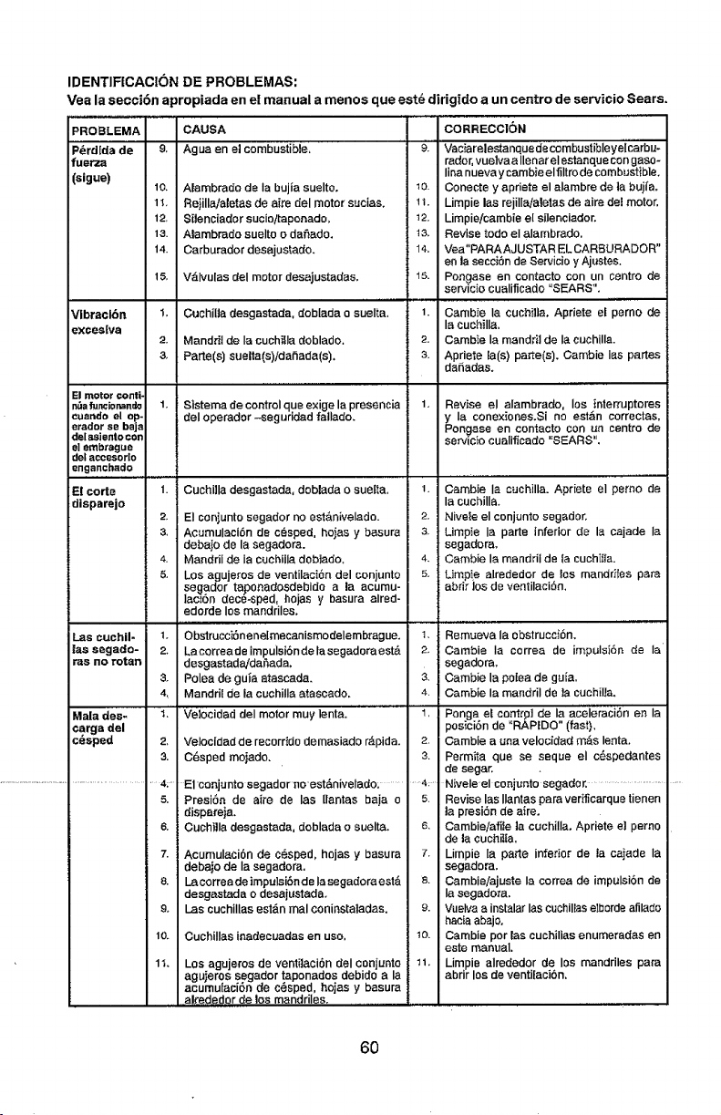
IDENTIFICACI6N DE PROBLEMAS:
Veala secci6n apropiada en el manual a menos que est_ dirigtdo aun centro de servicio Sears.
PROBLEMA CAUSA ' "CORRECC1ON
Agua en el combustible,
Alambrado de ia bujia suelto.
Rejilla/aletas de aire del motor sacias.
8ilenciader sucio!taponado,
Alambrado suelto o dalmatia.
Carburador desajus_ado.
P_rdlda de &
fuetza
(sigue)
l&
12.
13.
14.
l& V_Ivulas del motor desajustadas.
Vlbracl6n 1.
excesiva
2.
3,
El motor €onti-
n,',afuncionan_ 1,
cuartdo el op-
etador se bajs
de[ as]ento con
e] embrague
det sccesorlo
enganchsdo
E! corte 1.
disparejo
2,
CechffJa desgastada, doblada e suelta.
Mandril de la cuchitladoblade.
Parts(s) suelta(s)idafiada(s).
Las cuchll- 1,
tas segado- 2.
ras no rotan
3.
4_
Mala des- 1,
¢arga del
c_sped 2_
3.
................................................. 4/
5.
6.
7,
8.
&
l&
9'. Vaciar siesta nquede cembustible yei'carbu-
radar,vuelva a Ilenar el estanque con gaso-
linanueva y cambie elfiltro de combustible.
10. Conecte y apriete el alambre de ta buj{a.
1t. Limpie las rejillajaletas de airs del motor,
12. Limpie!cambie e[ sffenciador.
13. Revise todo el alambrado,
14. Vea"PARAAJUSTARELCARSURADOR"
an la secci6n de Setvicioy Ajustes.
15. Pongase en contacts con un centre de
servicio cualiflcade "SEARS".
t. Cambie la cuchilla. Apriete el perno de
la cuchilla.
2. Cambie la mandril de Ia cuchilla.
s. Apdete {a(s) parte(s). Cambie Ias partes
dafiadas.
,, ,,,,,
Sistema de controlqua exige la presencia
deI operador -seguridad fatlado.
Revise el alambrado, los interruptores
y Ia cone×iones.Si no estdn correctas,
Pongase an contacts con un centre de
servicio cualificado "SEARS".
CuchUla desgastada, doblada o suelta.
El conjunto segador no est_.nivelado.
Acumulaei6n de cesped, hojas y basura
debaio de la segadora.
Mandril de Ia cuchilla doblado.
Los agujeros de ventilaci6n del conjunto
segador taponadosdebido ala acurnu-
lac_6n dec6-sped, hojas y basura alred-
edorde los mandriles.
,,,,,,,,,,,,,,,,,
ObslrucciSnene[mecanismodelembrague.
Lacorreade impulsibnde lasegadoraest&
desgastada/da_ada,
Polea de gu_a atascada.
Mandril de la cuchilIa atascado.
Velocidad del motor muy lenta.
1. Cambie Ia cuchilla. Apdete el perno de
la cuchilla.
2. Niveleelconjunto segador.
3. Limpie Ia parte inferior de la cajade Ia
segadora.
4. Gamble la mandril de la cuchilia.
5. Limp!e alrededor de los mandriles pars
abrirlos de ventilaci6n.
3.
4.
I,
Velocidad de recorrido demasiado r_pida. 2r
C6sped me|adz. 3.
E1conjunto segador noest&nivelado; ..........4;-
Remt_evala obstrucci6n.
Cambie ia certes de impulsi6n de Ia
segadora.
Cambie la poise de guia,
Oambie la mandril de la euchiI_a.
Ponga et centrpl de ia ace'i'eraciSn an la
posiciSn de "RAPIDS" (fast),
Cambie a una velocidad m&s lenta.
Permita qua se seque el c6spedantes
de segar,
N;vele-el conjanto segador. ..............................
PresiSn de airs de las [lantas baiao
dispareja.
Ouchilla desgastada, doblada o suelta.
Acumulaci6n de c@sped, hojas y basura
debaio de Ia segadora,
La eorrea de impulsi6n de Iasegadora est&
desgastada o desajustada.
I_ascuchilIas est&n real eoniestaladas.
CuchilIas inedeeuadas en use,
Los agujeros de ventilaci6n deI conjunto
aguieros segador taponados debido ala
acumulaci6n de e6sped, hojas y basura
al_ededor de los mandriles.
5. Revise las Ilantas pars ver_carque tienen
la presi6n de airs.
& Cambie/afiIe ]a cuchilIa. Apriete el perno
de la euchiffa,
7. Limpie la parte inferior de fa cajade Ia
segadora.
& Cambieiajuste la cortes de impulsi6n de
Ia segadera.
9. Vuelvaa instalarIas cuchillas elbsrdeafilado
haciaabajo.
t& Cambie par las cuchilias enumeradas en
este manual.
11. Limpie alrededor de los mandriles pars
abrir los de venti[aci6n.
6O
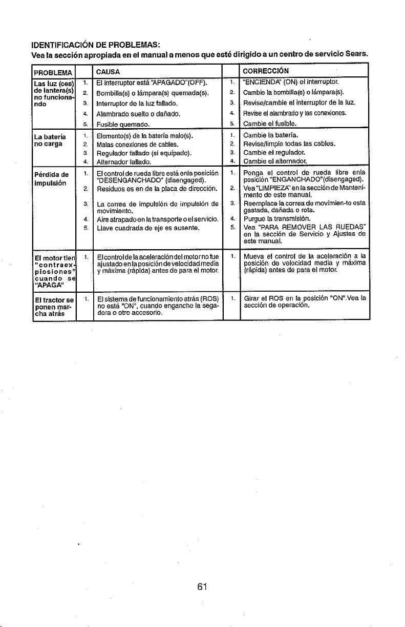
IDENTIFtCACI6N DE PROBLEMAS:
Vea la seccibn apropiada en el manual a menos que est_ dirigido a un centre de servicio Sears.
PROBLE_
Las luz (cesi
de lantera(sl
no funciona,
ndo
1.
2.
3.
4,
La baterla
no carga
5,
1.
2_
3.
4,
P_rdida de 1.
impulsiSn
2,
3.
4o
5_
El motor tien i.
"contraex-
ptosiones '*
cuando se
"APAGA"
El tractor se 1,
ponen mar-
cha atr_s
CAUSA
E[ inteirruptor esi& "APAGADO"(OFF).
Bombilla(s) o I&mpara(s) quemada(s).
Interrupter de Ia luz fallado.
AIambrado suelto o dahado.
Fus.!,blequemado,
Elements(s) de la bateria male(s).
Malas conexiones de cables.
Regulador fal]ado (st equipado),
A[temador fallado.
,, ,,,,,,,,,
El control de rueda libra est& enla posiciSn
"OESENGANCHADO" (disengaged).
Residues es en de ia piaca de direcciSn.
La correa de impulsionde impulsi6n de
movimiento.
Aire atrapado en la transporte o etsetvicio.
Liars cuadrada de eje es ausente.
tEicontroIde la aceleraciSn del motor no rue
ajustadoen taposici6ndevelocidad media
y m_lxima (r&pida) antes de para el motor,
El sistema defunc[onamienlo atr_s (ROS)
no est& "ON", cuando enganche la saga-
dora o otro accesorie.
1.
2.
3.
4.
5,
1.
2,
3,
4.
1.
2.
3.
4.
5,
CORRECCI6N
"ENCIENDA" (ON) el interrupter.
Cambie la bembilIa(s) o I&mpara(s).
Revise!cambie el interrupter de la Iuz.
Reviseel alambradoy Ias conexiones.
Cambie el fusible.
Cambie la baterfa.
Revise/Iimpie todas lascabIes.
Cambie el regulador.
Gamble el alternador.
,,, ,,,,,,,,,,,
Ponga el control de rueda libra enla
posici6n "ENGAN GHADO"(dIse ngaged).
Vea"LIMPIEZA_' en [a secci6n de Manterti-
menlo de este manual,
Reemplaee la correa de movimien-to esta
gastada, da_,ada o rata.
Purgue [a transmisi6n.
Vea "PARA REMOVER LAS RUEDAS"
en la seccibn de Servicio y Ajestes de
este manual.
Mueva el control de la aceIemcibn a Ia
posici6n de velocidad media y m_ima
(r_pida)antes de para el motor.
Girar el ROSen la posici6n "ON".Vea la
secciSn de operacton.
61

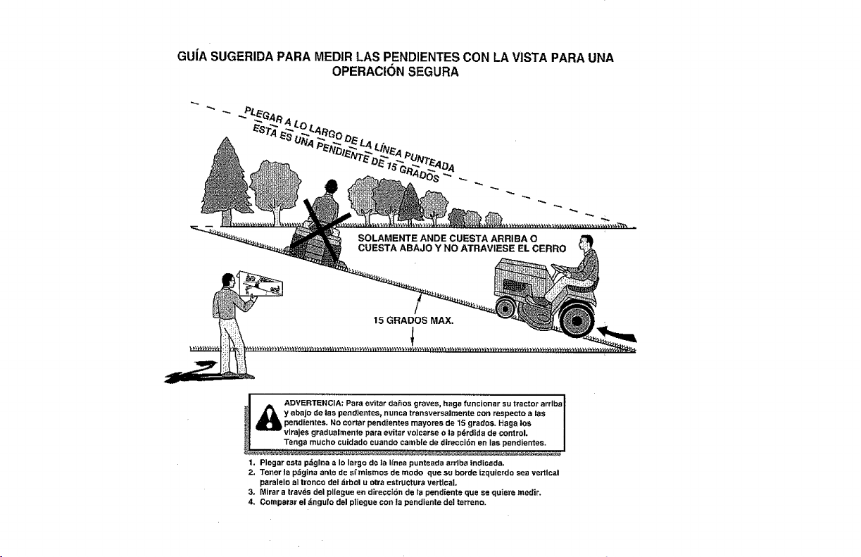
GUiA SUGERIDA PARA MEDIR LAS PENDIENTES CON LA VISTA PARA UNA
OPERACtON SEGURA
!
ADVERTENCIA; graves, hags funcionar su tractor arrlbs I
Para evitar daSos
y abajo de las pen_ientes, nunca transversalmente con reapecto aras I
pendientes. No corral pendientes mayores de 15 grados. Hags los |
vlraJes gradualmente pars evitar volcarse o la pdrdtda de control. I
Tenga mucho cuidado auando eatable de direcci6n enlas pendientes. I
1. Plegar esta pdglna a Io largo de ta Ifnea punteada arriba indicada.
2. Tenet Japdgina ante de sl'mismos de modo que su borde |zquicrdo sea vertical
paralelo al tronco de| _rbol u otra estructUra vertical
3. Mirar a trav6s del pliegue en direcel6n de la pendiente que se quiere medir.
4. Compsrar el .'_ngulo del pliegue coo ta pendiente de! terreno.

i NEED MORE HELP?
i You'[[ find the answeT and luo_e o_ mar_agemyhome.com - _or f_ee!
i . Find this and all your other product manuals online. _':
• i • Get answers from our team of home experts. _
• Get a personalized maintenance plan for your home.
• Find information and tools to help with home projects.
manage home
brought to you by Sears
_S
Your Home
For repair - in your home - of all major brand appliances,
lawn and garden equipment, or heating and cooling systems,
no matter who made it, no matter who sold it{
For the replacement parts, accessories and
owner's manuals that you need to do-it-yourself.
For Sears professional instaI]ation of home appliances
and items like garage door openers and water heaters.
1-800-4-MY-HOME ® A_ytime, dayor night
(1_00-459..4663) (U.S.A.and Csnada)
www.$eaPs.co:03 WWW,seait$; C_
Our Home
For repair of carry-in products like vacuums, lawn equipment,
and electronics, ca[I or go on-line for the nearest
Sears Parts and Repair Center.
!_i_ %800-488-1222 Anyt{me,dayor night (U.S.A.only}
_ _,_._e_._
._ ................... TO purchase a protection agreement (U.S.A.) ..................... _i_
or maintenanCe agreement (Canada) on a product serviced by Sears: _!
_-_ 1-800-B27=6655 (U.S.A.) %800-361-5665 (Carat) i_
_i_ Para pedir servP,.iode reparadOn Au Canada pour service en fran(;ais: _
_ a domic_lio, y para ordenar piezas: 1-800-LE-FOYER Mc _{_i
_s_ 1.888.SU.HOGAR _ 0_7) _
11.01,12 BD
©_P_'_tSB_ands, LL_
® Regislere_ Trademark / TM T{ademark t s_ $ervi_.._ Mark oI _ ea_*sBrands, LLC
® Marca Registr_da ! TM Marca de Fdbrica / s_ Marca _e ServiCed de Sears Bra_0s. LLC
w: M,trque de cOmmerce I _'_ M_rque dttpoe_e de Seats Bran_s, LLC
Printedin the U.S.A.


