Loading ...
Loading ...
Loading ...
,,,,,,,,,,,,,,,,,,, ,,,,,,,,, ................................................
HOW TO ASSEMBLE YOUR BLOWER
WARNING
STOP THE ENGINE BEFORE OPENING
THE VACUUM iNLET DOOR OR
ATTEMPTING TO INSERT OR REMOVE
THE VACUUM TUBES. THE ENGINE
MUST BE STOPPED AND THE IMPELLER
BLADES NO LONGER TURNING TO
AVOID SERIOUS INJURY FROM THE
ROTATING BLADES
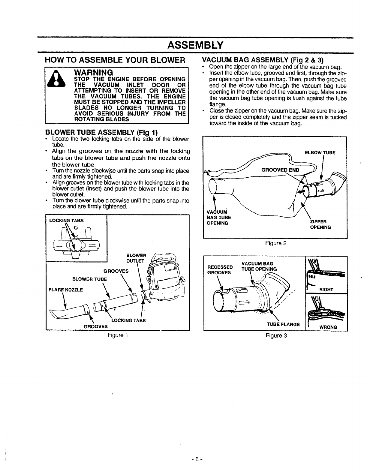
pLOWER TUBE ASSEMBLY (Fig 1)
Locatethe two locking tabs on the side of the blower
tube.
• Align the grooves on the nozzle with the locking
tabs on the blower tube and push the nozzle onto
the blower tube
• Turn the nozzle clockwise until the parts snap into place
and are firmlytightened.
• Align grooves on the blower tube with locking tabs in the
blower outlet (inset) and pushthe blower tube into the
blower outlet.
• Turn the blower tube clockwise until the parts snap into
place and are firmly tightened.
LOCKING TABS
BLOWER
OUTLET
GROOVES
BLOWER TUBE
FLARE NOZZLE
LOCKING TABS
GROOVES
Figure 1
VACUUM BAG ASSEMBLY (Fig 2 & 3)
• Open thezipper on the large end of the vacuum bag.
• Insert the elbow tube, grooved end first, through the zip-
per opening in the vacuum bag. Then, push the grooved
end of the elbow tube through the vacuum bag tube
opening in the other end of the vacuum bag. Make sure
the vacuum bag tube opening is flush against the tube
flange.
• Close the zipper on the vacuum bag. Make sure the zip-
per is closed completely and the zipper seam is tucked
toward the inside of the vacuum bag.
ELBOW TUBE
v_uu_i
BAG TUBE
OPENING
ZIPPER
OPENING
Figure 2
VACUUM BAG
RECESSED TUBE OPENING
TUBE FLANGE
Figure 3
WRONG
-6-
Loading ...
Loading ...
Loading ...