Loading ...
Loading ...
Loading ...
Setting Surface Controls
FEATURE OVERVIEW
Sizes & assembly of Surface Burners
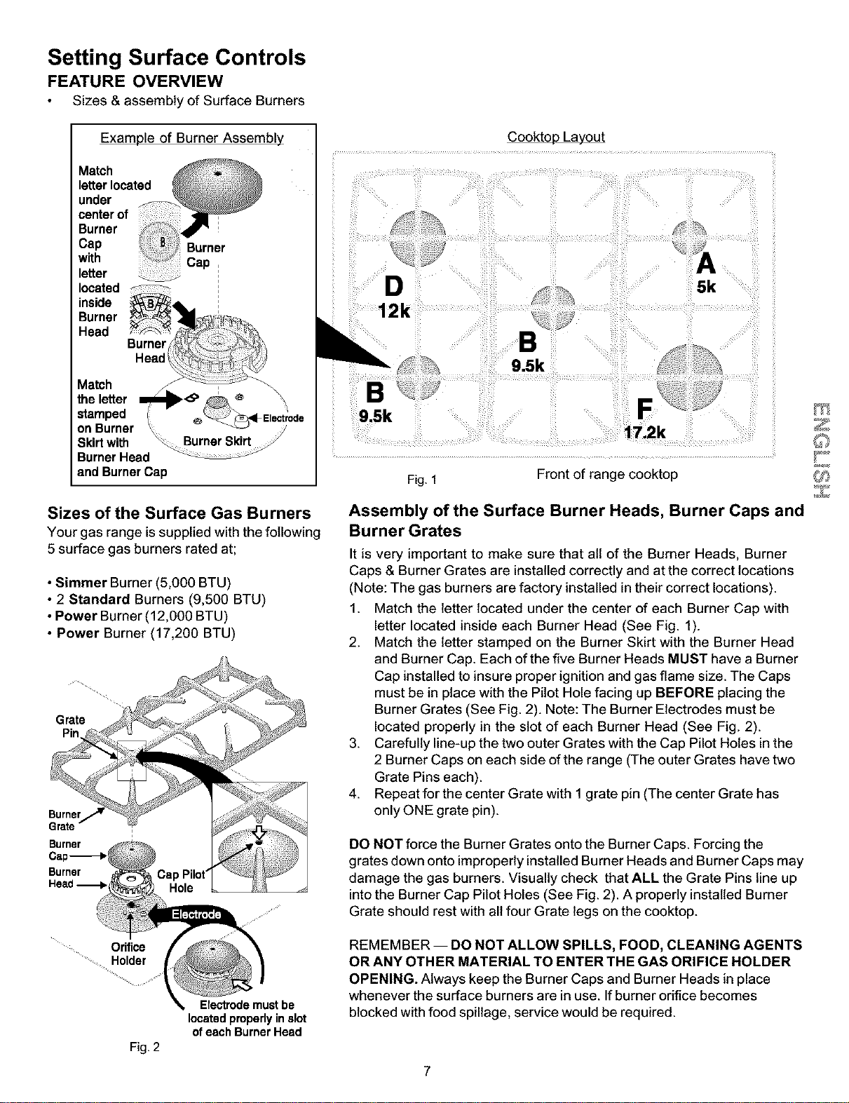
Example of Burner Assembly
Match
letterlocated
under
centerof
Burner
Cap
with
letter
located
inside
Burner
Head
Burner
Head
Match
the letter
stamped
on Burner
Skirt with
Burner Head
and Burner Cap
i
i
Burner
Cap
Electrode
D
12k
Fig. 1
Cooktop Layout
5k
Front of range cooktop
Sizes of the Surface Gas Burners
Your gas range issupplied with the following
5 surface gas burners rated at;
• Simmer Burner (5,000 BTU)
• 2 Standard Burners (9,500 BTU)
• Power Burner (12,000 BTU)
• Power Burner (17,200 BTU)
Grate
Pin
Burner
Grate
Burner
Burner
Head _,
Orifice
Holder
Fig. 2
Electrodemustbe
locatedproperlyin slot
ofeach Burner Head
Assembly of the Surface Burner Heads, Burner Caps and
Burner Grates
It is very important to make sure that Bit of the Burner Heads, Burner
Caps & Burner Grates are installed correctly and at the correct locations
(Note: The gas burners are factory installed in their correct locations).
1. Match the letter located under the center of each Burner Cap with
letter located inside each Burner Head (See Fig. 1).
2. Match the letter stamped on the Burner Skirt with the Burner Head
and Burner Cap. Each of the five Burner Heads MUST have a Burner
Cap installed to insure proper ignition and gas flame size. The Caps
must be in place with the Pilot Hole facing up BEFORE placing the
Burner Grates (See Fig. 2). Note: The Burner Electrodes must be
located properly in the slot of each Burner Head (See Fig. 2).
3. Carefully line-up the two outer Grates with the Cap Pilot Holes in the
2 Burner Caps on each side of the range (The outer Grates have two
Grate Pins each).
4. Repeat for the center Grate with 1 grate pin (The center Grate has
only ONE grate pin).
DO NOT force the Burner Grates onto the Burner Caps. Forcing the
grates down onto improperly installed Burner Heads and Burner Caps may
damage the gas burners. Visually check that ALL the Grate Pins line up
into the Burner Cap Pilot Holes (See Fig. 2). A properly installed Burner
Grate should rest with all four Grate legs on the cooktop.
REMEMBER -- DO NOT ALLOW SPILLS, FOOD, CLEANING AGENTS
OR ANY OTHER MATERIAL TO ENTER THE GAS ORIFICE HOLDER
OPENING. Always keep the Burner Caps and Burner Heads in place
whenever the surface burners are in use. Ifburner orifice becomes
blocked with food spillage, service would be required.
7
Loading ...
Loading ...
Loading ...