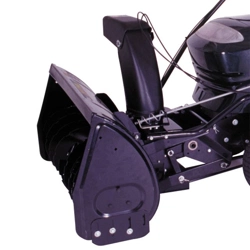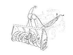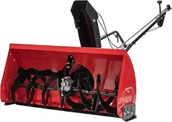

42" SNOW THROWER
CMXGZBF71248371
IF YOU HAVE QUESTIONS
OR COMMENTS, CONTACT US.
1-888-331-4569 WWW.CRAFTSMAN.COM
INSTRUCTION MANUAL
COMPATIBLE WITH:
T1, T2, and T3 Series Craftsman Riding Mowers

WARNING: Read all safety warnings and all
instructions. Failure to follow the warnings and
instructions may result in damage or seriousinjury.
WARNING: Never modify the product or any part of
it. Damage or personal injury couldresult.
WARNING: To reduce the risk of injury, read the
instructionmanual.
If you have any questions or comments about this or
any product, call toll free at: 1-888-331-4569.
Definitions: Safety Alert Symbols and Words
This instruction manual uses the following safety alert symbols and words to alert you to hazardous situations and your risk
of personal injury or property damage.
DANGER: Indicates an imminently hazardous situation which, if not avoided, will result in death or seriousinjury.
WARNING: Indicates a potentially hazardous situation which, if not avoided, could result in death or seriousinjury.
CAUTION: Indicates a potentially hazardous situation which, if not avoided, may result in minor or moderateinjury.
(Used without word) Indicates a safety related message.
NOTICE: Indicates a practice not related to personal injury which, if not avoided, may result in propertydamage.
SAFETY WARNINGS
WARNING: Read all safety warnings,
instructions, illustrations and specifications
provided with this tool. Failure to follow all
instructions listed below may result in fire and/or
seriousinjury.
SAVE ALL WARNINGS AND
INSTRUCTIONS FOR FUTURE
REFERENCE
Safety Warnings
a ) Read the tractor and snow blade owner's manuals
and know how to operate your tractor before using
tractor with snow blade attachment.
b ) Never operate tractor and snow blade without
wearing proper clothing suited to weather conditions
and operation of controls.
c ) Never allow children to operate tractor and snow
blade, and do not allow adults to operate without
proper instructions.
d ) Always begin with transmission in first (low) gear and
gradually increase speed as conditions permit.
Look for this symbol to point out
important safety precautions. It
means — Attention!! Become
alert!! Your safety is involved.
1
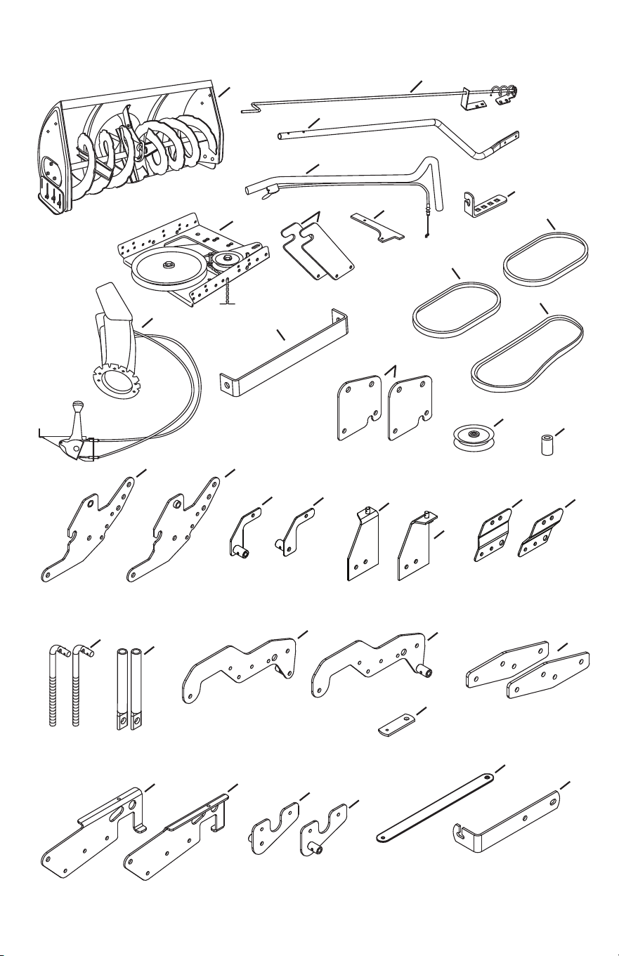
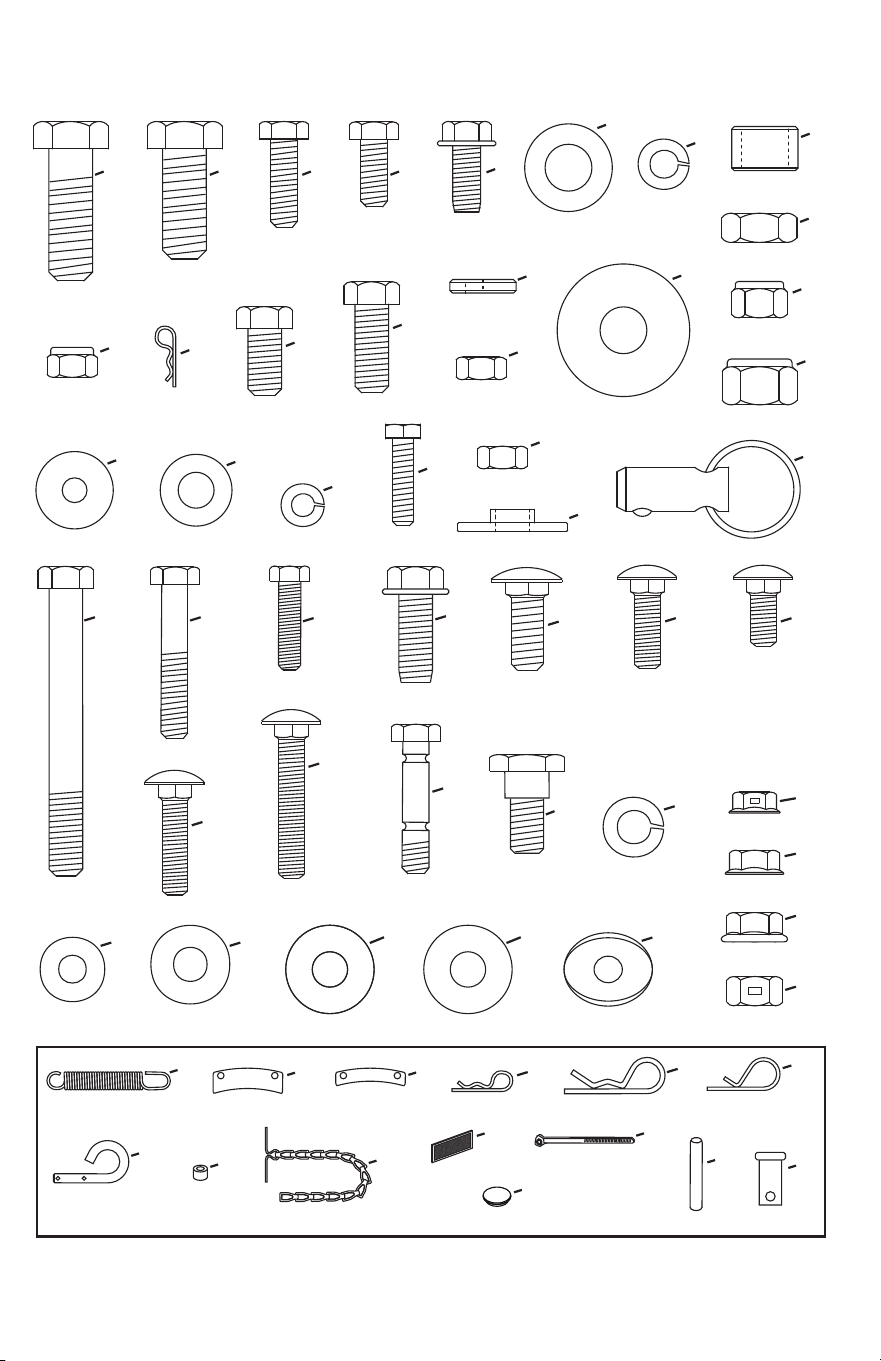
CARTON CONTENTS
46989
41353
42992
11
2
4
6
8
12
5
1
9
3
17
18
19
25
26
27
28
30
29
31 32
33
34
35
36
20
21
22
23 24
14
13
27509BL1
25728BL1
24558BL1
27914BL3
10
7
27016BL1
48883
25780
15
16
67269BL1
41346
27902BL3 27901BL3
68402BL3 68403BL3
28414BL3
28413BL3
41352BL1
67268BL1
67533BL1
27340BL1
67532BL1
67052BL1 67053BL1
67267BL1 67266BL1
27900BL3
27011BL1
27010BL1
25722BL1
2
A
x2
B
x2
C
x15
D
x11
E
x4
F
x12
G
x7
I
x2
J
x4
K
x8
O
x4
L
x2
P
x2
Q
x8
R
x4
S
x4
T
x4
U
x4
V
x4
W
x4
X
x2
M
x4
N
x6
H
x20
Y
x2
42977
47810
47134
43407
43001
43064
42846
R19172410
41657
HA21362
43019
27231
43086
R19171616
47630
43182
43063
43351
43020
R19131316 43177
42300
44685
42847
43083
GG
x2
DD
x6
FF
x2
LL
x7
SS
x10
QQ
x6
RR
x1
NN
x1
PP
x2
TT
x2
KK
x7
II
x2
MM
x22
Z
x1
46938
43084
43661
47631
43350
44215
43682
44326
43080
42849
43003
43088
43081
47605
44695
43082
47572
46584
47598
UU
x1
ZZ
x2
XX
x2
WW
x3
VV
x3
YY
x4
A6
x2
A1
x2
A2
x1
A3
x2
A4
x2
46959 27809
27810
HA3090
43343
43055
43038
46963
726-0178
47788
HA9822
42991
42842
23727
A7
x1
A5
x1
A8
x2
AA
x2
BB
x6
CC
x6
JJ
x4
48106
HH
x2
EE
x4
OO
x3
43070
NOT SHOWN ACTUAL SIZE
HARDWARE PACKAGE CONTENTS
3
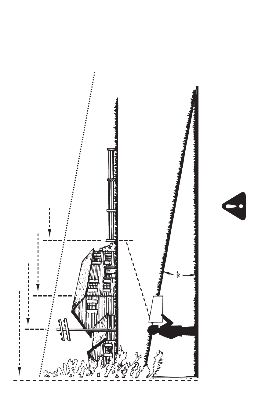
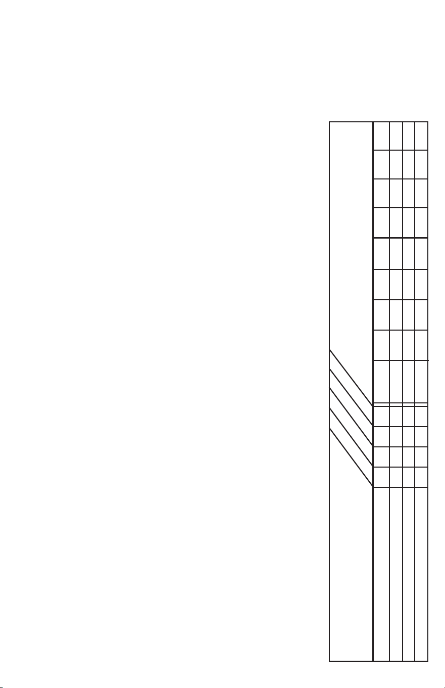
SLOPE GUIDE
(Keep this sheet in a safe place for future reference.)
Attach the chain to the spring on the lower idler arm.
Use this guide to determine if a slope is safe for the
operation of your tractor and snow thrower. Refer also to
the instructions in your vehicle owners manual.
A POWER POLE
A CORNER OF A BUILDING
OR A FENCE POST
FOLD ALONG DOTTED LINE, REPRESENTING A 10 DEGREE SLOPE
SIGHT AND HOLD THIS LEVEL WITH A VERTICAL TREE
CAUTION: Do not operate your tractor and snow thrower
on a slope in excess of 10 Degress. Verify your tractor's
towing and braking capabilities before operating on a slope.
Avoid any sudden turns or maneuvers while on a slope.
4
TOOLS REQUIRED FOR ASSEMBLY
1. (1) Pliers
2. (1) Hammer
3. (2) 7/16" Wrenches
4. (2) 1/2" Wrenches
5. (2) 9/16" Wrenches
6. (2) 3/4" Wrenches
7. (1) Screw Driver
8. (1) Knife
9. General Purpose Grease
REMOVAL OF PARTS FROM CARTON
1. Remove all parts and hardware packages from the
carton. Lay out parts and hardware and identify using
the illustrations on pages 1 and 2.
NOTE: Not all of the supplied parts and hardware will be
needed for your particular tractor. Unneeded items may be
discarded after you have completed assembly and checked
operation of unit. DO NOT DISCARD the two spare shear
bolts and 5/16" nylock nuts. Refer to the Service and
Adjustments section on page 28 and 29.
CAUTION: Before starting to assemble the
snow thrower, remove the spark plug wire(s),
set the parking brake and remove the key
from the tractor ignition.
CAUTION: Do not begin assembling until
the tractor engine, muffler and exhaust
deflector have been allowed to cool off.
TRACTOR PREPARATION
Before performing these instructions, refer to the Service
and Adjustments section of your tractor owner's manual for
specific safety instructions.
1. Allow engine, muffler and exhaust deflector to cool
before beginning.
2. Remove any front or rear attachment which is mounted
to your tractor.
3. Remove the mower deck. Refer to your tractor owner's
manual for removal instructions. Mark all loose parts and
save for reassembly.
4. Remove the tractor hood. Refer to your tractor owner's
manual for removal instructions.
IMPORTANT: Right hand (R.H.) and left hand (L.H.) side of
the tractor are determined from the operators position while
seated on the tractor.
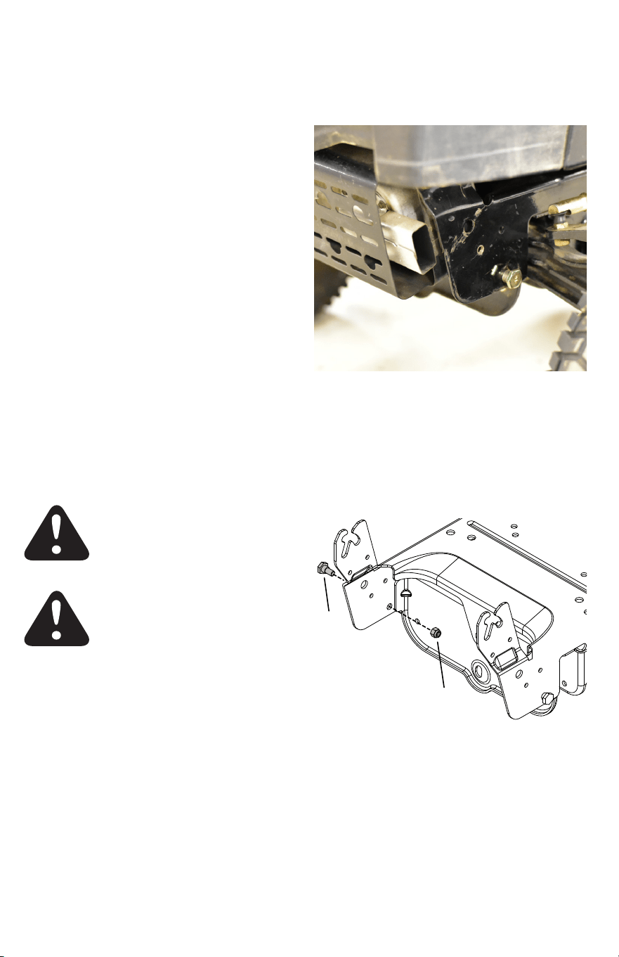
IDENTIFY YOUR TRACTOR: IF YOUR TRACTOR
FRAME MATCHES THE STYLE SHOWN
BELOW, FOLLOW THESE INSTRUCTIONS.
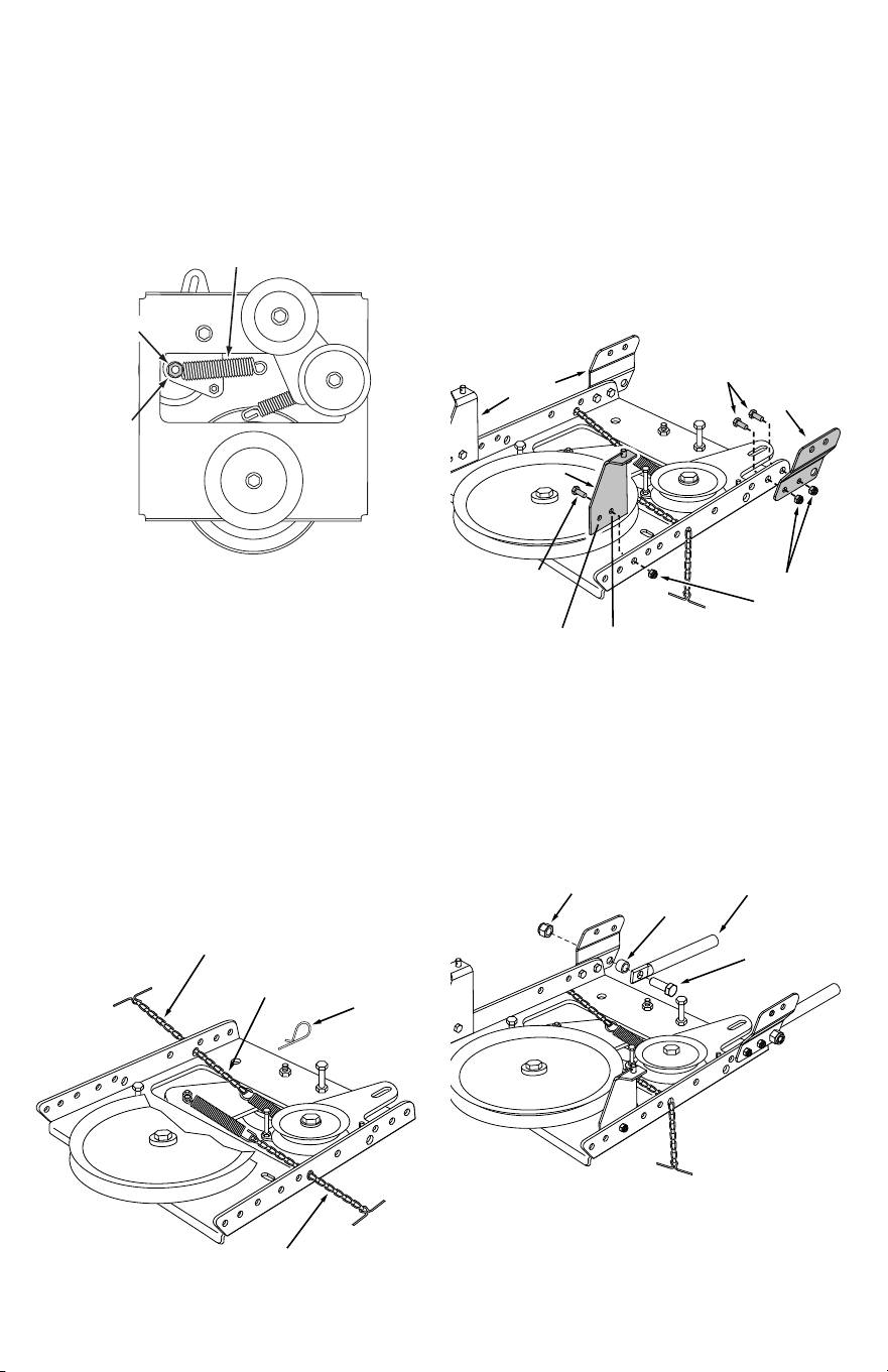
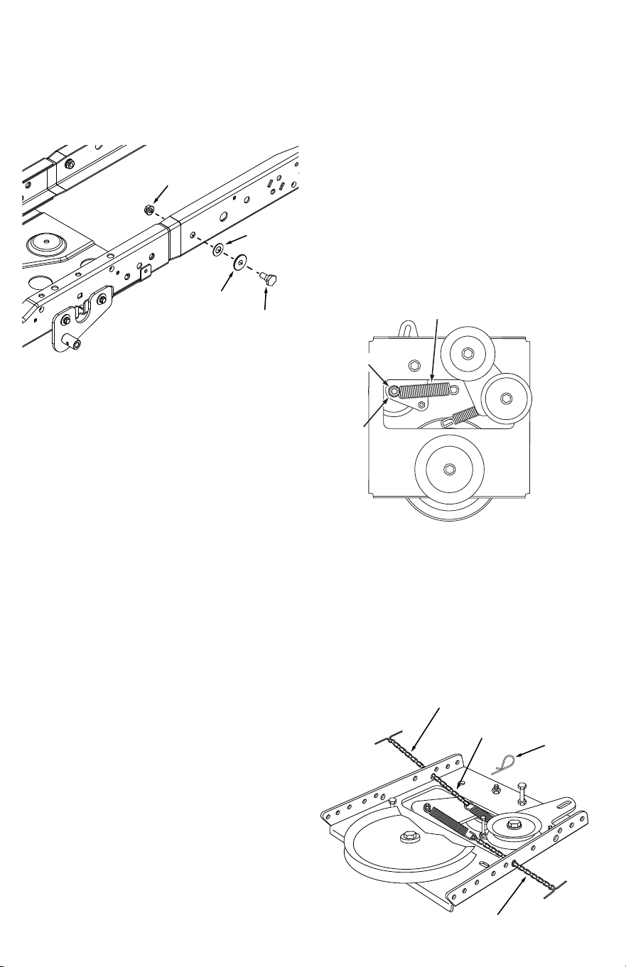
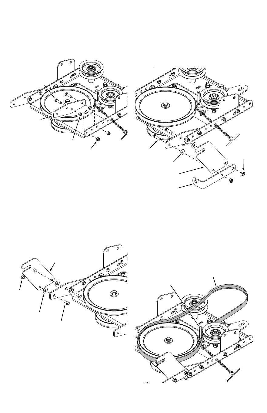
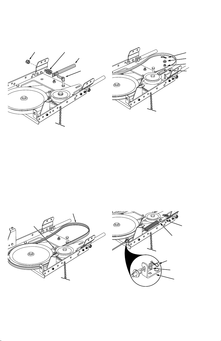
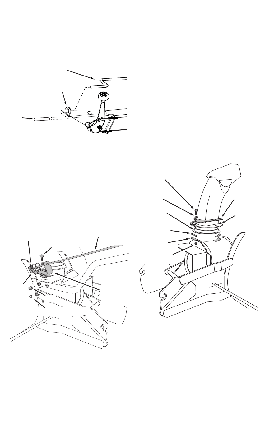
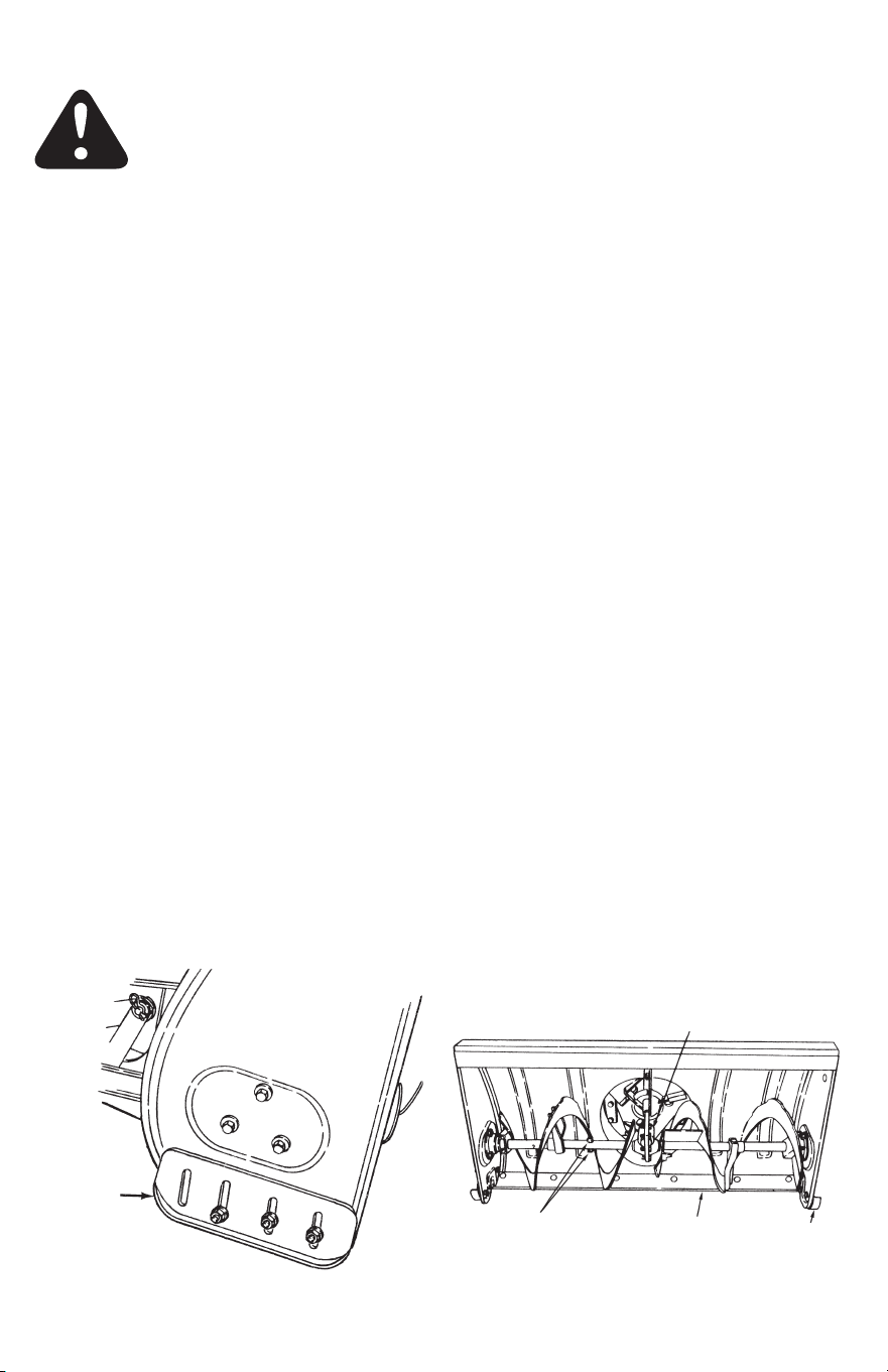
STEP 1: (Fig. 1)
1. Assemble a shoulder bolt (JJ) and a 3/8" nylock nut (K)
to the holes shown on each side of the tractor frame.
JJ
K
Fig. 1
COMPATIBLE WITH:
T1, T2, and T3 Series Craftsman
Riding Mowers
5
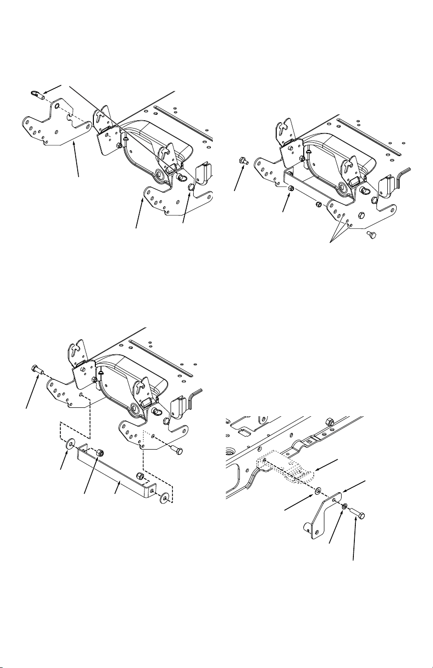
STEP 2: (Fig. 2)
1. Place a side plate (17,18) onto each shoulder bolt (JJ)
and install two quick release pins (P) as shown.
P
18
JJ
17
STEP 3: (Fig. 3)
1. Attach the frame brace (5) between the side plates
using two 1/2" x 1-1/4" hex bolts (B), 1/2" x 1-1/2"
washers (H) and 1/2" nylock nuts (O).
H
O
B
5
SS
JJ
Use hole that measures
10" above ground
STEP 4: (Fig. 4)
1. Measure from the center of the three holes indicated
in figure 4 to select the hole that is approximately 10"
above the ground in both front mount plates.
2. Install a shoulder bolt (JJ) and 3/8" nylock nut (SS) in the
selected hole in each front mount plate.
STEP 5: (Fig. 5)
1. Remove the thread forming bolt from the hole in the
footrest bracket on the left side of the tractor frame.
2. Attach the L.H. hanger bracket (20) to the empty hole
using a 5/16" x 1" hex bolt (C), a 5/16" lock washer (G),
and a 5/16" flat washer (MM). Place the flat washer
between the hanger bracket and the footrest bracket.
3. Repeat on the right side of the tractor frame using the
the R.H. hanger bracket (19).
C
MM
FOOTREST
BRACKET
20
G
Fig. 2
Fig. 3
Fig. 4
Fig. 5
6
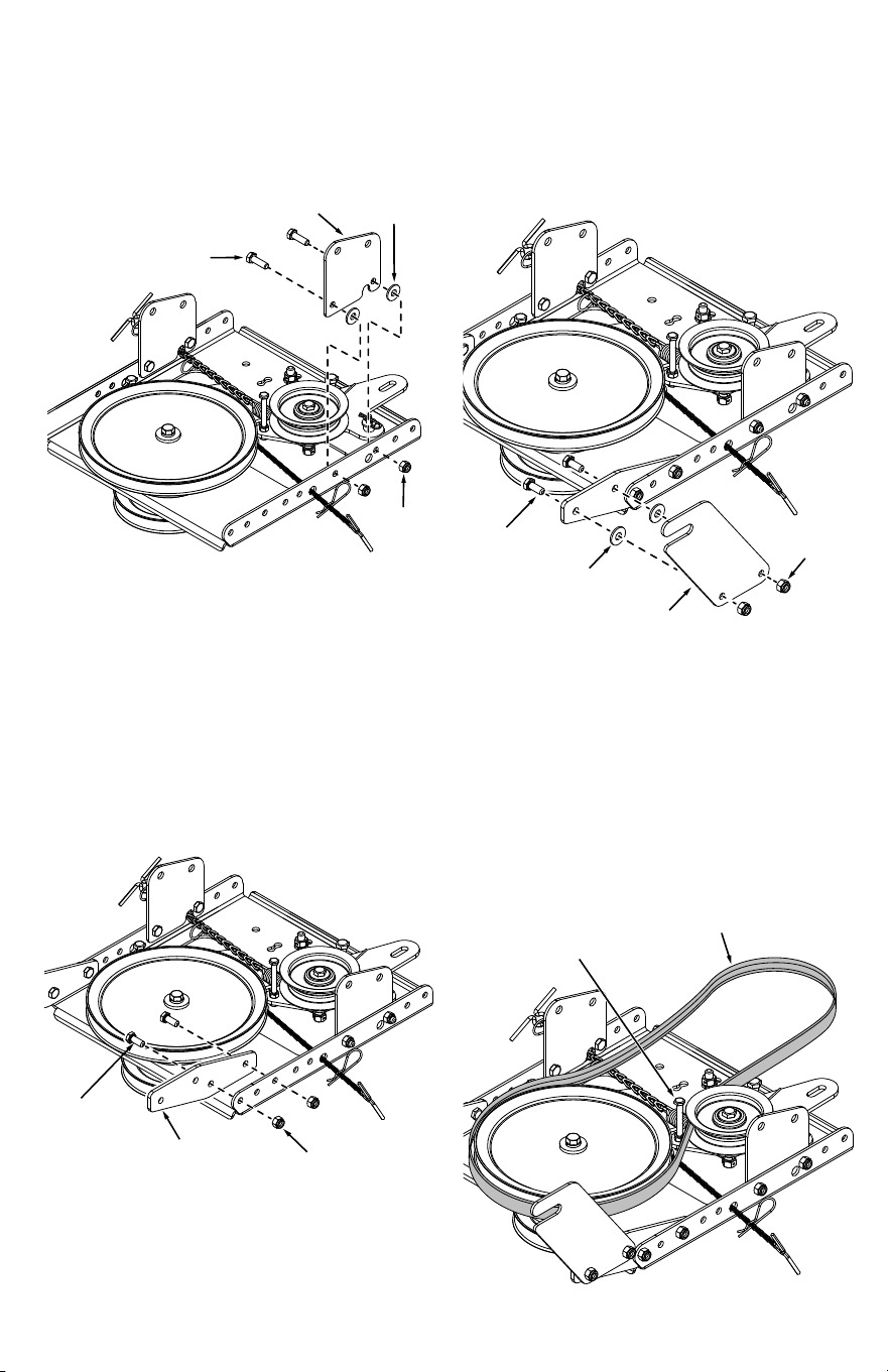
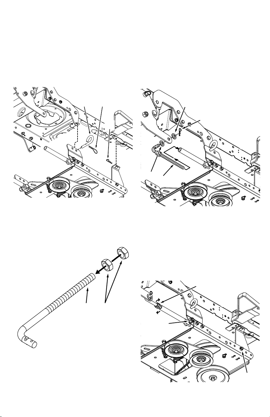
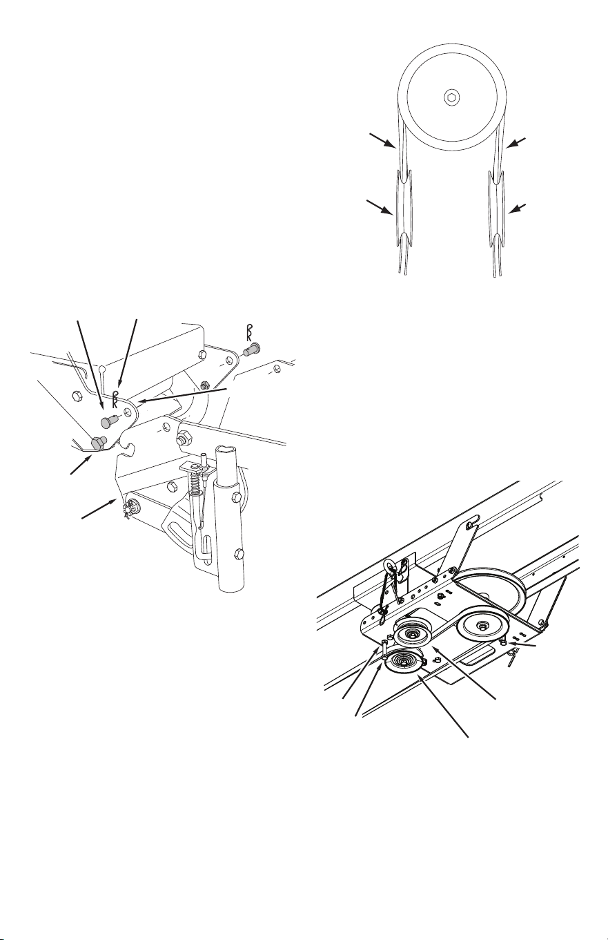
STEP 8: (Fig. 8)
1. Refer back to step 4. If you used the top hole indicated
in step 4, use hole A in this step. If you used one of the
two lower holes, use hole B in this step.
2. Attach the R.H. (21) and L.H. (22) rear frame brackets on
the inside to either hole A or B using one 5/16" x 3/4"
hex bolt (D) and 5/16" nylock nut (Q) for each bracket.
Do not tighten yet.
3. Assemble the R.H. (23) and L.H. (24) front frame brackets
on the outside using two 5/16" x 3/4" hex bolts (D)
and 5/16" nylock nuts (Q) for each bracket.
D
D
Q
24
21
23
22
Q
HOLE (B)
HOLE (A)
YY
A3 (lower idler arm)
A3 (upper idler arm)
THIRD LINK
26
I
O
A
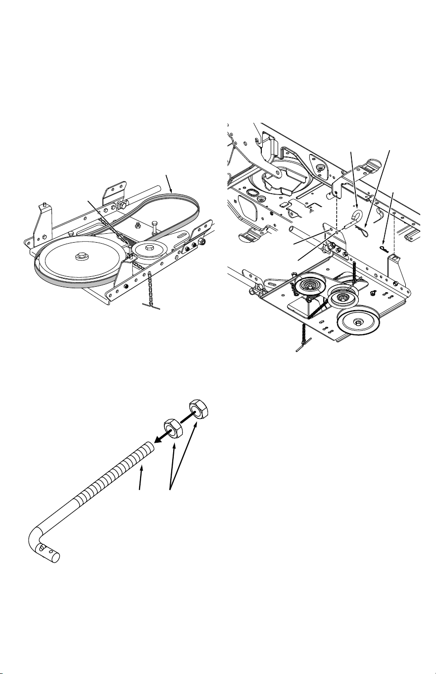
STEP 9: (Fig. 9)
1. Assemble the two support tubes (26) to the inside
of each front frame bracket using a 1/2" x 1-1/2" hex
bolt(A), a 1/2" spacer (I) and a 1/2" nylock nut (O) for
each bracket. Do not tighten yet.
TT
UU
ATTACH
SPRING
HERE
STEP 6: (Fig. 6)
1. Turn the clutch idler assembly upside down.
2. Attach the spring to the bottom of the upper idler arm.
Hook the spring onto the bolt that extends through
the nut on the bottom of the upper idler arm and then
install a 3/8" hex lock nut (TT) onto the bolt. Leave
enough space for the spring to pivot.
STEP 7: (Fig. 7)
1. Insert tensioning chains (A3) through the holes shown
and attach to the springs on the upper and lower idler
arms.
2. Attach a 3/32" hairpin cotter (YY) to the chain attached
to the upper idler arm, placing it in the third link from
the spring.
Fig. 6
Fig. 7
Fig. 8
Fig. 9
7
J
25
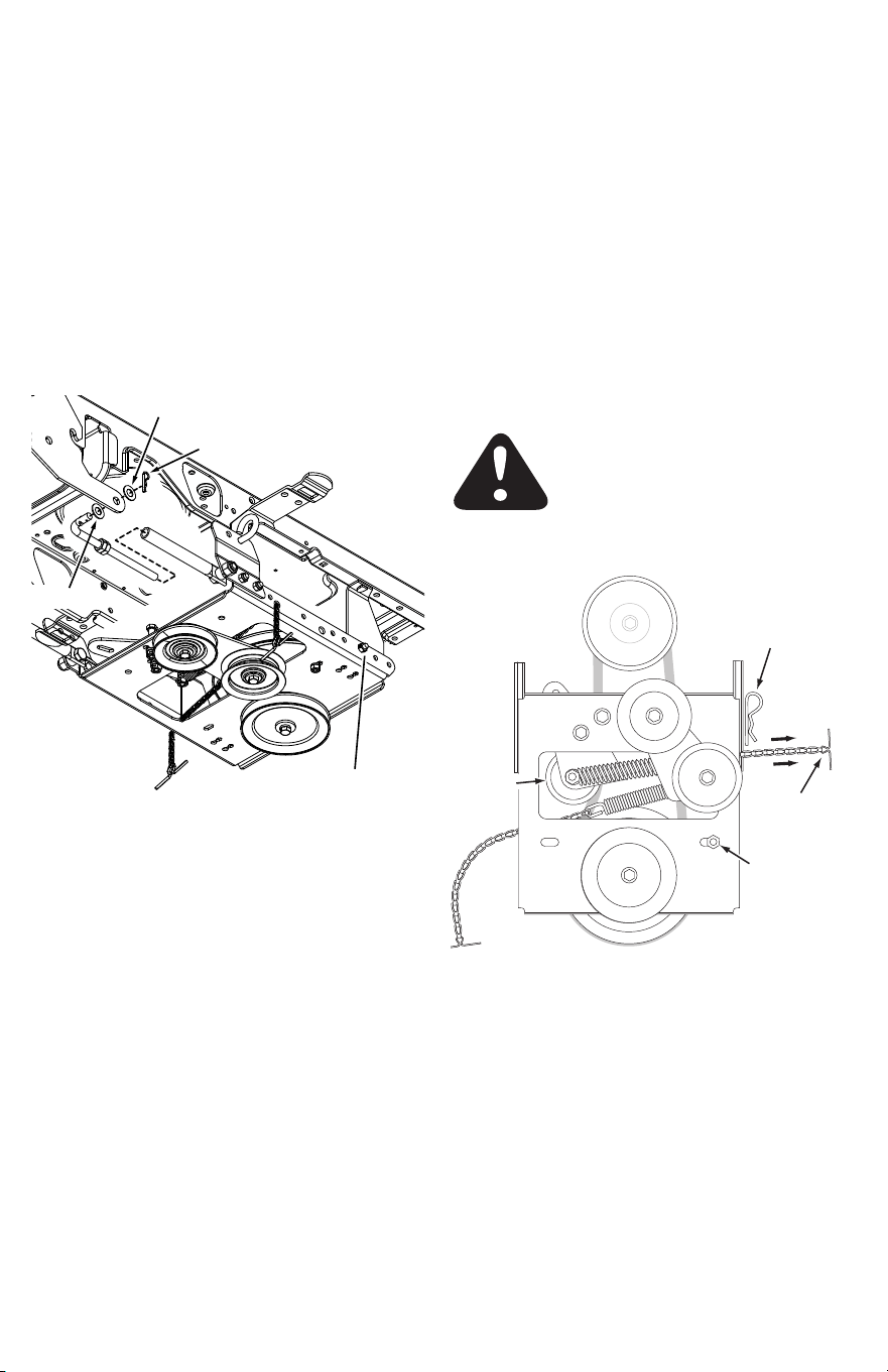
STEP 11: (Fig. 11)
1. Assemble two 1/2" jam nuts (J) all the way onto the
threads of each support link (25).
HOLE A
HOLE B
R
YY
A1
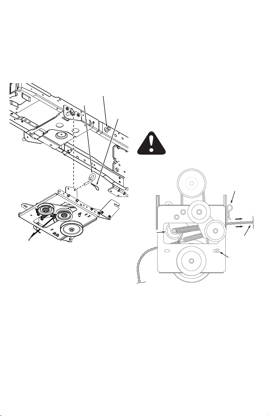
STEP 12: (Fig. 12)
1. Attach the front frame brackets to the two hanger
brackets on the tractor frame using two pivot lock
pins(A1) and 1/8" hairpin cotters (YY).
2. Attach the rear frame brackets to the bottom of the
tractor frame using two small 5/64" hairpin cotters (R).
12 or 13
LOOSEN BOLT
STEP 10: (Fig. 10)
1. Two drive belts are supplied with the snow thrower. If
you used hole A in step 8, use the 52" drive belt (12). If
you used hole B, use the 55" drive belt (13).
2. Slightly loosen the hex bolt next to the flat idler pulley.
Install the drive belt between the hex bolt and the flat
idler pulley with the flat side of the belt against the
pulley. Retighten the hex bolt.
3. Loop the belt around the large v-pulley, placing it
between the pulley and the hex bolt next to the pulley.
Fig. 10
Fig. 11
Fig. 12
8
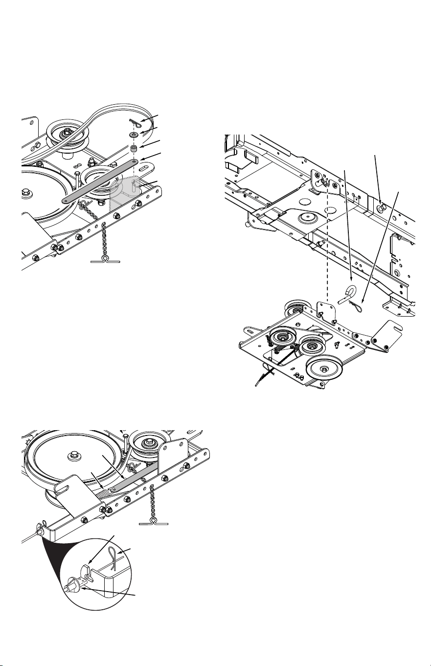
STEP 13: (Fig. 13)
1. Assemble a 1/2" x 1" (H) washer onto the bent end of
a support link and then insert the threaded end into
a support tube and the bent end into the rear hole in
a front mounting plate, Assemble another 1/2" x 1"
(H) washer onto the end of the link and secure it with
a small 5/64" hairpin cotter (R). Repeat for the other
support link.
2. Tighten the bolt and nut in each rear frame bracket.
3. Tighten the bolt and nut in each support link.
4. Tighten the jam nuts so that all looseness is eliminated
from the support links and support tubes.
H
R
H
TIGHTEN BOLT
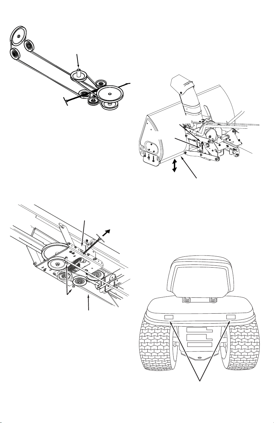
STEP 14: (Fig. 14)
1. Remove the belt guard for the PTO pulley on the
tractor. Refer to "Cutting Deck Removal" in the SERVICE
AND MAINTENANCE section of your tractor Operator's
Manual.
2. Install the drive belt onto the tractor's PTO pulley. You
may need to temporarily lift the belt from the large
pulley on the clutch idler assembly.
3. Reinstall the belt guard for the tractor's PTO pulley. Be
sure the belt guard is installed in the notch on the side
of the tractor's electric clutch.
4. Place tension on the belt by pulling the left side
tensioning chain out as far as the 3/32" hairpin cotter
(XX) will allow. Secure the chain in this position by
inserting a 1/8" hairpin cotter (YY) through the chain.
DO NOT start the engine until the PTO
pulley belt guard has been reinstalled.
The tractor's electric clutch could be
damaged.
GO TO ASSEMBLY OF SNOW THROWER
SECTION ON PAGE 21.
YY
ENGINE
PULLEY
KEEPER
BOLT & NUT
IDLER
PULLEY
CHAIN
(L.H. SIDE)
VIEWED FROM UNDERNEATH
Fig. 13
Fig. 14
9
IDENTIFY YOUR TRACTOR: IF YOUR TRACTOR
FRAME MATCHES THE STYLE SHOWN
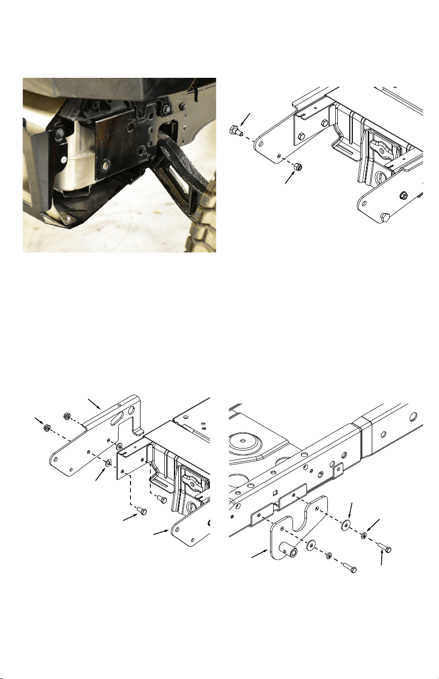
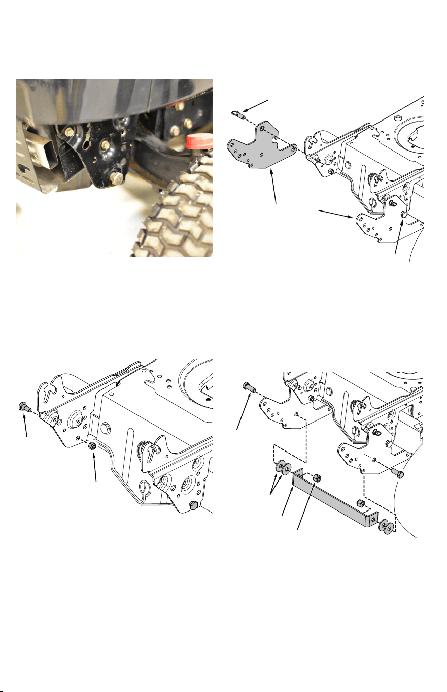
BELOW, FOLLOW THESE INSTRUCTIONS.
STEP 1: (Fig. 15)
1. Remove the bolt holding on the front frame strap.
2. Attach the R.H. front mounting plate (31) to the tractor
frame using two 3/8 x 3/4" hex bolts (S), 3/8" washers
(U), and 3/8" flange nuts (SS).
3. Repeat for L.H. front mounting plate (32).
STEP 2: (Fig. 16)
1. Assemble a shoulder bolt (JJ) and 3/8" nylock nut (K) to
both front mounting plates.
S
32
U
31
SS
K
JJ
STEP 3: (Fig. 17)
1. Remove the two bolts holding on the rear frame strap.
2. Attach the L.H. hanger bracket (34) using two M6 x 1
x 25 bolts (W), 1/4" lock washers (V), and .281 x .875
washers (T) to the holes that you just removed bolts
from.
3. Repeat for R.H. hanger bracket (33).
V
20
T
W
Fig. 15
Fig. 16
Fig. 17
10
TT
UU
ATTACH
SPRING
HERE
STEP 5: (Fig. 19)
1. Turn the clutch idler assembly upside down.
2. Attach the spring (UU) to the bottom of the upper
idler arm. Hook the spring onto the bolt that extends
through the nut on the bottom of the upper idler arm
and then install a 3/8" hex lock nut (TT) onto the bolt.
Leave enough space for the spring to pivot.
STEP 6: (Fig. 20)
1. Insert tensioning chains (A3) through the holes shown
and attach to the springs on the upper and lower idler
arms.
2. Attach a 3/32" hairpin cotter (YY) to the chain attached
to the upper idler arm, placing it in the third link from
the spring.
YY
A3 (lower idler arm)
A3 (upper idler arm)
THIRD LINK
THIS SECTION IS FOR TRACTORS WITH AN
ELECTRIC ATTACHMENT CLUTCH
If your tractor has a manual attachment clutch
go to page 13.
STEP 4: (Fig. 18)
1. Install a shoulder bolt (JJ), shoulder spacer (X), 1/2" x 1"
washer (F), and 3/8" flanged nut (SS) to the sides of the
tractor frame.
JJ
X
F
SS
Fig. 18
Fig. 19
Fig. 20
11
STEP 9: (Fig. 23)
1. Attach the rear pulley frame brackets (10) to the outside
of the rear extension straps (16) using four 5/16 x 3/4"
hex bolts (D), 5/16" washers (MM), and 5/16" nylock
nuts (Q).
STEP 10: (Fig. 24)
1. Slightly loosen the hex bolt next to the flat idler pulley.
Install the 55" drive belt (13) between the hex bolt and
the flat idler pulley with the flat side of the belt against
the pulley. Retighten the hex bolt.
2. Loop the belt around the large v-pulley, placing it
between the pulley and the hex bolt next to the pulley.
D
Q
MM
10
13
LOOSEN BOLT
STEP 7: (Fig. 21)
1. Attach the front pulley frame brackets (7) to the inside
of the clutch idler assembly using four 5/16 x 1" hex
bolts (C), 5/16" washers (MM), and 5/16" nylock nuts (Q).
STEP 8: (Fig. 22)
1. Attach the rear extensions straps (16) to the inside of the
clutch idler assembly using four 5/16 x 3/4" hex bolts
(D) and 5/16" nylock nuts (Q).
C
MM
Q
7
Q
D
16
Fig. 21
Fig. 22
Fig. 23
Fig. 24
12
STEP 12: (Fig. 26)
1. Remove the belt guard for the PTO pulley on the
tractor. Refer to "Cutting Deck Removal" in the SERVICE
AND MAINTENANCE section of your tractor Operator's
Manual.
2. Install the drive belt onto the tractor's PTO pulley. You
may need to temporarily lift the belt from the large
pulley on the clutch idler assembly.
3. Reinstall the belt guard for the tractor's PTO pulley. Be
sure the belt guard is installed in the notch on the side
of the tractor's electric clutch.
4. Place tension on the belt by pulling the left side
tensioning chain out as far as the 3/32" hairpin cotter
(XX) will allow. Secure the chain in this position by
inserting a 1/8" hairpin cotter (YY) through the chain.
STEP 11: (Fig. 25)
1. Attach the clutch/idler assembly to the tractor frame.
Hook the notched rear pulley frame brackets onto the
two shoulder bolts (JJ) assembled to the outside of the
tractor frame. Lift the front of the assemble and attach
it to the hanger brackets (LH) and (RH) using two pivot
lock pins (A1) and 1/8" hairpin cotters (YY).
YY
A1
JJ
DO NOT start the engine until the PTO
pulley belt guard has been reinstalled.
The tractor's electric clutch could be
damaged.
GO TO ASSEMBLY OF SNOW THROWER
SECTION ON PAGE 21.
YY
ENGINE
PULLEY
KEEPER
BOLT & NUT
IDLER
PULLEY
CHAIN
(L.H. SIDE)
VIEWED FROM UNDERNEATH
Fig. 25
Fig. 26
13
THIS SECTION IS FOR TRACTORS WITH AN
MANUAL ATTACHMENT CLUTCH
If your tractor has an electric attachment clutch
go back to page 10.
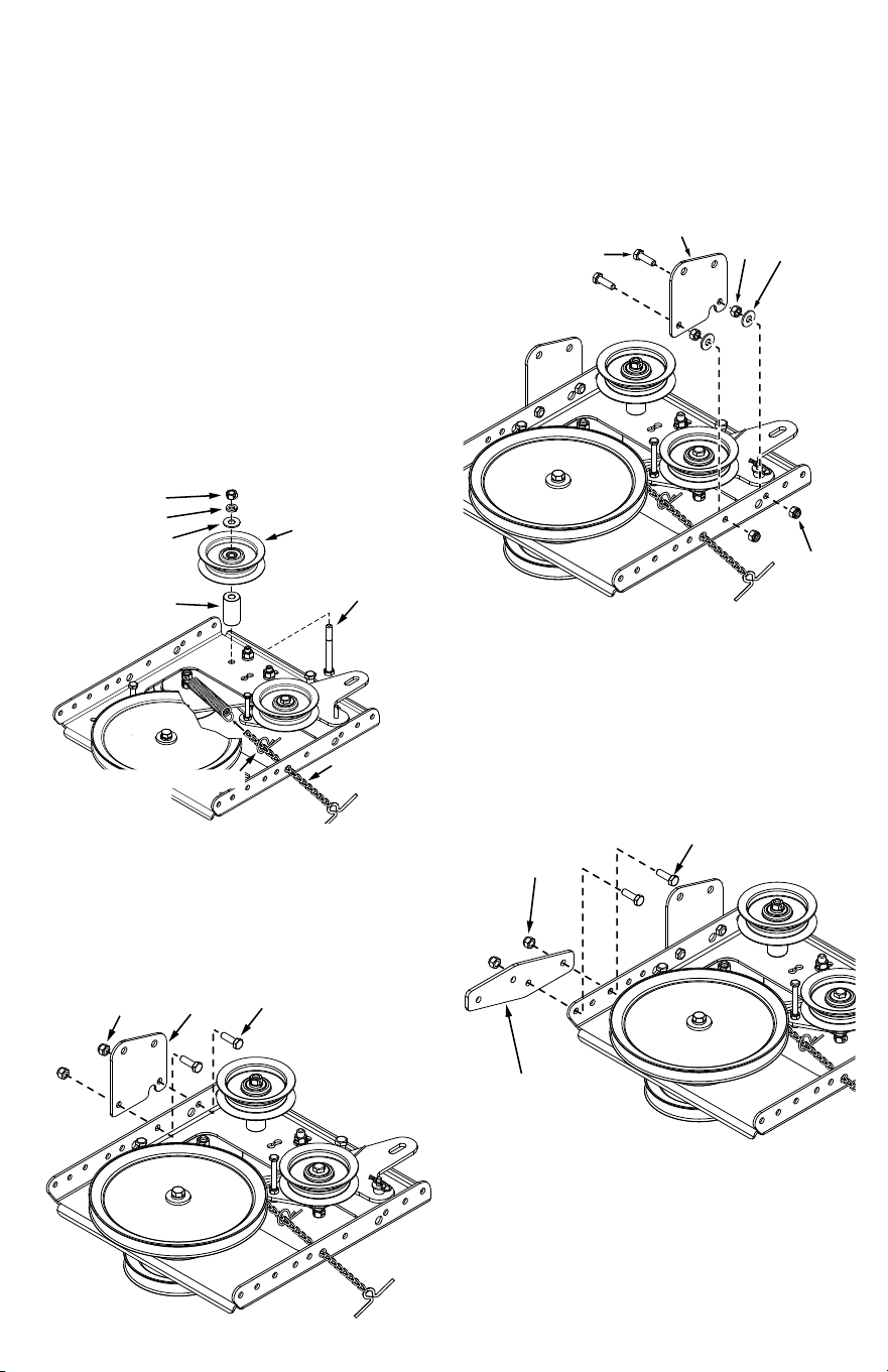
STEP 1: (Fig. 27)
1. Attach the pulley (long end of hub facing down) and
the large 3/8" spacer (16) to the clutch frame. Use a
3/8" x 3-1/4" hex bolt (Z), a 3/8" washer (O), a 3/8" lock
washer (KK) and a 3/8" hex lock nut (TT).
2. Install a tensioning chain (A3) through the hole shown
and then insert a 3/32" hairpin cotter (ZZ) into the 4th
link.
3. Attach the chain to the spring on the lower idler arm.
16
KK
TT
OO
Z
A3
PULLEY
(long end of
hub down)
3/32" HAIRPIN COTTER (ZZ)
IN 4TH LINK
STEP 3: (Fig. 29)
1. Attach a front pulley frame bracket (7) to the right inside
of the clutch idler assembly using two 5/16 x 1" hex
bolts (C), 5/16" hex nuts (Y), 5/16" washers (MM), and
5/16" nylock nuts (Q).
C
MM
Q
7
Y
STEP 4: (Fig. 30)
1. Attach a rear extension strap (30) to the left outside
of the clutch idler assembly using two 5/16 x 3/4" hex
bolts (D) and 5/16" nylock nuts (Q).
STEP 2: (Fig. 28)
1. Attach a front pulley frame bracket (7) to the left outside
of the clutch idler assembly using two 5/16 x 3/4" hex
bolts (D) and 5/16" nylock nuts (Q).
Q
D
30
Q
7
D
Fig. 27
Fig. 28
Fig. 29
Fig. 30
14
STEP 7: (Fig. 33)
1. Attach a rear pulley frame bracket (10) and cable
bracket(36) to the right rear extension strap (30) using
two 5/16 x 1" hex bolts (C), 5/16" washers (MM), and
5/16" nylock nuts (Q).
C
Q
36
10
MM
STEP 8: (Fig. 34)
1. Slightly loosen the hex bolt next to the flat idler pulley.
Install the 55" drive belt (13) between the hex bolt and
the flat idler pulley with the flat side of the belt against
the pulley. Retighten the hex bolt.
2. Loop the belt around the large v-pulley, placing it
between the pulley and the hex bolt next to the pulley.
13
LOOSEN BOLT
STEP 5: (Fig. 31)
1. Attach a rear extension strap (30) to the right inside of
the clutch idler assembly using two 5/16 x 1" hex bolts
(C), 5/16" hex nuts (Y), 5/16" nylock nuts (Q).
Q
Y
30
C
STEP 6: (Fig. 32)
1. Attach a rear pulley frame bracket (10) to the left rear
extension strap using two 5/16 x 3/4" hex bolts (D),
5/16" washers (MM), and 5/16" nylock nuts (Q).
D
10
Q
MM
Fig. 31
Fig. 32
Fig. 33
Fig. 34
15
STEP 11: (Fig. 37)
1. Attach the clutch/idler assembly to the tractor frame.
Hook the notched rear pulley frame brackets onto the
two shoulder bolts (JJ) assembled to the outside of the
tractor frame. Lift the front of the assemble and attach
it to the hanger brackets (LH) and (RH) using two pivot
lock pins (A1) and 1/8" hairpin cotters (YY).
YY
A1
JJ
R
36
35
CABLE
HOUSING
GUIDE
SPRING
STEP 10: (Fig. 36)
1. Move the tractor's attachment clutch lever to the
disengaged position.
2. Attach the spring at the end of the tractor's clutch cable
to the cable strap (35). Secure the cable housing guide
to the cable bracket (36) using a 5/64" hair cotter pin (R).
XX
LL
A2
WELDED PIN
35
STEP 9: (Fig. 35)
1. Install the cable strap (35), the 1/4" spacer (A2), and
a1/4" washer (LL) onto the welded pin on the idler
arm. Secure the parts to the pin with a 5/64" hairpin
cotter(XX).
GO TO ASSEMBLY OF SNOW THROWER
SECTION ON PAGE 21.
Fig. 35
Fig. 36
Fig. 37
16
IDENTIFY YOUR TRACTOR: IF YOUR TRACTOR
FRAME MATCHES THE STYLE SHOWN
BELOW, FOLLOW THESE INSTRUCTIONS.
STEP 1: (Fig. 38)
1. Assemble a shoulder bolt (JJ) and a 3/8" nylock nut (SS)
to the holes shown on each side of the tractor frame.
STEP 2: (Fig. 39)
1. Place a side plate (17,18) onto each shoulder bolt (JJ)
and install two quick release pins (P) as shown.
P
18
17
JJ
JJ
SS
STEP 3: (Fig. 40)
1. Attach the frame brace (5) between the side plates
using two 1/2" x 1-1/4" hex bolts (B), four 1/2" x 1-1/2"
washers (H) and two 1/2" nylock nuts (O).
H
O
B
5
Fig. 38
Fig. 39
Fig. 40
17
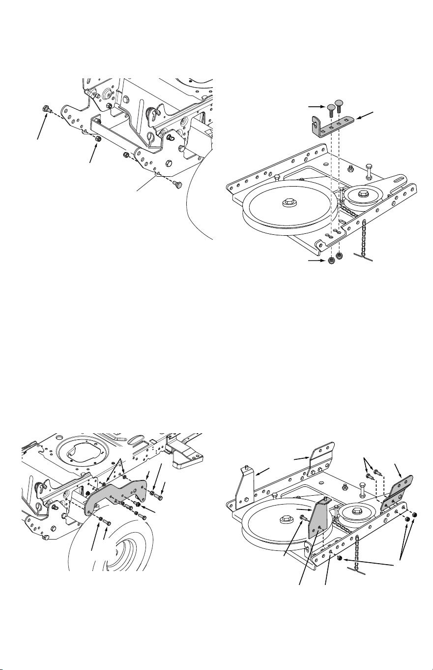
STEP 6: (Fig. 43)
1. Assemble the cable bracket (36) to the outside half
of the double holes in the bottom of the clutch/idler
assembly using two 5/16" x 3/4" carriage bolts (FF) and
5/16" nylock nuts (Q).
36
FF
Q
K
27
L
M
(3) C
(3) Q
E
STEP 5: (Fig. 42)
1. Attach the L.H. frame support (27) to the tractor. Install
a 3/8" x 1" hex bolt (L), a bushing (M) and a nylock nut
(K) in the rear hole of the support. Install a 5/16" x 3/4"
thread forming bolt (E) and a bushing (M) in the fourth
hole of the support. Install three 5/16" x 1" hex bolt (C)
and 5/16" nylock nuts (Q) in the front three holes of the
support. Tighten after all bolts are installed. Repeat this
step using the R.H. frame support (28).
STEP 4: (Fig. 41)
1. Install a shoulder bolt (JJ) and 3/8" nylock nut (SS) in the
bottom hole in each front mount plate (17 and 18).
SS
Use bottom hole
JJ
STEP 7: (Fig. 44)
1. Attach the R.H. and L.H. rear frame brackets (21,22) to
the inside of the clutch/idler assembly. Use one 5/16"
x 3/4" hex bolt (D) and 5/16" nylock nut (Q) in the front
hole of each bracket and the third hole in the clutch/
idler assembly. Do not tighten yet.
2. Assemble the R.H. and L.H. front frame brackets (23,24)
to the inside of the clutch/idler assembly using two
5/16" x 3/4" hex bolts (D) and 5/16" nylock nuts (Q) for
each bracket.
D
2423
22
21
D
Q
THIRD HOLE
FRONT HOLE
Fig. 41
Fig. 42
Fig. 43
Fig. 44
18
STEP 9: (Fig. 46)
1. Select the 52" (shortest) drive belt (12) Slightly loosen
the hex bolt next to the flat idler pulley. Install the drive
belt between the hex bolt and the flat idler pulley with
the flat side of the belt against the pulley. Retighten
the hex bolt.
2. Loop the belt around the large v-pulley, placing it to the
inside of the hex bolt that is beside the pulley.
LOOSEN BOLT
12
A2
R
LL
29
STEP 10: (Fig. 47)
1. Place the extension strap (29), a 1/4" spacer (A2) and a
1/4" washer (LL) onto the welded pin on the idler arm.
Install a 5/64" hair pin cotter (R) in the welded pin.
26
F
O
A
STEP 8: (Fig. 45)
1. Assemble the two support tubes (26) to the inside of
each front frame bracket (23 and 24) using a 1/2" x
1-1/2" hex bolt (A), three 1/2" x 1" washers (F) and a 1/2"
nylock nut (O) for each tube. Do not tighten yet.
STEP 11: (Fig. 48)
1. Disengage the tractor's attachment clutch lever.
2. Place the clutch/idler assembly onto the floor at the
right side of the tractor.
3. Hook the end of the tractor's clutch cable spring to the
extension strap (29) on the clutch/idler assembly.
4. Attach the tractor's mower clutch cable to the cable
bracket (36) on the clutch/idler assembly. Secure the
cable housing guide (groove down) to the cable bracket
using the original collar and a 5/64" hair cotter pin (R).
36
R
COLLAR (from tractor)
CLUTCH CABLE
SPRING
29
Fig. 45
Fig. 46
Fig. 47
Fig. 48
19
STEP 14: (Fig. 51)
1. Insert the threaded end of a support link (25) into the
support tube on the left side of the tractor. Assemble a
1/2" x 1" washer (F) onto the bent end of the link and
insert it into the hole in the front mount plate (17).
Assemble another 1/2" x 1" (F) washer onto the end of
the link and secure it with a small 5/64" hairpin cotter
(R). Repeat on the right hand side.
J
25
STEP 13: (Fig. 50)
1. Assemble two 1/2" jam nuts (J) all the way onto the
threads of each support link (25).
STEP 12: (Fig. 49)
1. Attach the front of the clutch/idler assembly to the two
frame support brackets (27 and 28) you assembled in
step 5, using two pivot lock pins (A1) and 1/8" hairpin
cotters (YY).
2. Attach the rear of the clutch/idler assembly to the
bottom of the tractor frame using two small 5/64"
hairpin cotters (R).
R
YY
A1
F
F
25
R
VIEWED FROM
UNDER LEFT SIDE
STEP 15: (Fig. 52)
1. Tighten the bolt and nut in each rear frame bracket.
2. Tighten the bolt and nut in each support tube.
3. Tighten the jam nuts on each support link against the
end of the support tube until slack is gone.
(3) 1/2" JAM NUTS
(1) TIGHTEN
(2) TIGHTEN
VIEWED FROM UNDER LEFT SIDE
Fig. 49
Fig. 50
Fig. 51
Fig. 52
20
STEP 16: (Fig. 53)
1. Move the tractor's attachment clutch lever to the
disengaged position.
2. Remove the belt guard for the PTO pulley on the
tractor's engine. Refer to "Cutting Deck Removal" in the
SERVICE AND MAINTENANCE section of your tractor
Operator's Manual.
3. Install the drive belt onto the engine's PTO pulley. You
may first need to temporarily lift the belt from the large
pulley on the clutch idler assembly.
4. Reinstall the belt guard.
PTO
PULLEY
IDLER
PULLEY
Right Side
of Tractor
BELT
GUARD
VIEWED FROM UNDERNEATH
Fig. 53
GO TO ASSEMBLY OF SNOW THROWER
SECTION ON PAGE 21.
21
ASSEMBLY OF THE SNOW THROWER
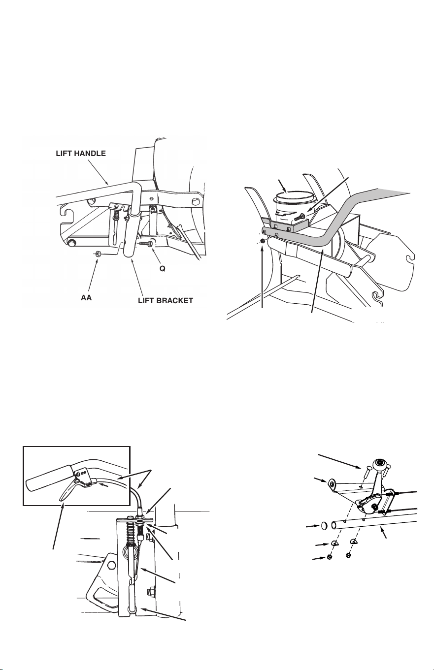
Step 1: (Fig. 54)
1. Place the lift handle into the lift bracket on the right side
of the snow thrower. Fasten the handle to the bracket
using two 5/16" x 1-3/4" hex bolts (AA) and 5/16"
Nylock nuts (Q).
NOTE: Be sure the lift release cable's plastic covering stays
inserted into the trigger assembly for the next step.
AA
Q
LIFT BRACKET
LIFT HANDLE
Step 2: (Fig. 55)
1. Push the lift handle down into the locked position.
Insert the end of the cable wire into the hole in the
lift rod. Place the threaded fitting into the slot in the
lift bracket, with one hex nut above and one hex nut
and the lock washer below the slot. Tighten the nuts,
adjusting them to eliminate slack in the cable wire. Refer
also to the Service and Adjustments section.
HINT: For easier assembly of the lift release cable, tilt the
snow thrower forward onto the spiral auger.
LIFT RELEASE
CABLE
HEX NUT
LOCK
WASHER
HEX NUT
CABLE
WIRE
LIFT
ROD
TRIGGER
ASSEMBLY
Step 3: (Fig. 56)
1. Tilt the snow thrower back down to the ground.
2. Remove the nylon tie which fastens the auger drive belt
to the discharge housing, leaving the belt assembled
around the pulleys.
3. Remove the nylon tie which fastens the chute crank rod
to the crank rod support tube (2).
4. Assemble the crank rod support tube to the bracket on
the left side of the discharge housing using two 5/16" x
1-1/4" carriage bolts (GG), and 5/16" Nylock nuts (Q).
GG
DISCHARGE
HOUSING
Q
2
Step 4: (Fig. 57)
1. Install the plug (A5) into the end of the crank support
tube.
2. Attach the chute tilt control assembly to the top side of
the crank rod support tube (2) using two 5/16" x 1-3/4"
carriage bolts (HH), bowed washers (PP) and 5/16"
nylock nuts (Q).
CHUTE TILT CONTROL
ASSEMBLY
HH
PP
Q
A5
2
Fig. 54
Fig. 55
Fig. 56
Fig. 57
22
Step 5: (Fig. 58)
1. Install the chute crank rod (4) into the plastic bushing in
the chute tilt control assembly.
2. Install the grip (A7) onto the chute crank rod.
4
CHUTE TILT CONTROL
ASSEMBLY
A7
Step 6: (Fig. 59)
1. Attach the chute crank rod (4) assembly brackets to the
plastic bracket on the left side of the discharge housing.
Align the chute crank bracket beneath the rod support
bracket and assemble both to the plastic bracket using
two 5/16" x 1" carriage bolts (EE), 5/16" washers (MM)
and 5/16" Nylock nuts (Q).
2. Do not tighten yet.
CHUTE CRANK
BRACKET
4
ROD
SUPPORT
BRACKET
EE
SPIRAL
MM
Q
Step 7: (Fig. 60)
1. Coat the top of the ring around the discharge opening
with general purpose grease.
2. Place the discharge chute (facing forward) onto the ring.
Place the anti-rotation bracket (11) on top of the chute
flange, aligning it with the holes on the right hand side
of the flange. Attach the three chute spacers (WW) and
chute keepers (VV) to the bottom of the flange using six
1/4" x 1" hex bolts (BB), 1/4" flat washers (LL), and 1/4"
flanged lock nuts (QQ). Tighten carefully so that the nuts
are snug but do not dig into the plastic chute keepers.
3. Position the crank rod spiral (see figure 51) so that it
does not rub against the bottoms of the notches in the
chute flange. Tighten the nuts.
4. Turn the crank rod to check if the chute rotates freely. If
not, loosen the bolts and nuts that attach the chute to
the flange by 1/4 turn each.
5. Secure the control cables to the crank rod support tube
using a nylon tie.
WW
11
QQ
LL
BB
GREASED
SURFACE
FLANGE
VV
Fig. 58
Fig. 59
Fig. 60
23
ATTACHING SNOW THROWER TO TRACTOR
Step 1: (Fig. 61)
1. Place the snow thrower on a flat, level surface.
2. Extend the auger belt out behind the snow thrower,
keeping the belt assembled to the snow thrower
pulleys.
3. Roll the tractor up behind the snow thrower, centering it
between the snow thrower's mounting plates.
4. Raise the rear of the snow thrower by lifting up on the
lift handle until the notches in the mounting plates align
with the shoulder bolts (JJ) in the tractor's side plates.
Guide the bolts into the notches.
5. Delay installing the clevis pins (A8) until you have
assembled the belt as instructed in steps 56 and 57.
MOUNTING
PLATE
SIDE PLATE
JJ
A8
YY
Step 2: (Fig. 62)
1. The auger belt comes pre-assembled to the pulleys on
the snow thrower housing. Make sure the belt passes
over the top of the auger pulley and then twists 1/4 turn
to pass underneath each side idler pulley. The "V" side of
the belt must mate with the grooves of the pulleys.
IDLER
PULLEY
AUGER
PULLEY
TWIST
1/4 TURN
TWIST
1/4 TURN
IDLER
PULLEY
Step 3: (Fig. 63)
1. Push the lift handle down to increase slack in the belt.
2. Swing the lower idler arm over to the left side.
3. Slightly loosen the belt keeper bolts located beside the
idler arm V-pulley and the rear V-pulley.
4. Place the auger belt around the rear V-pulley and
between the two pulleys on the idler arm. The "V"
side of the belt must be seated in the grooves of the
V-pulleys.
5. Retighten the two keeper bolts.
KEEPER
BOLT
IDLER ARM V-PULLEY
IDLER ARM
FLAT PULLEY
KEEPER
BOLT
NUT
Fig. 61
Fig. 62
Fig. 63
24
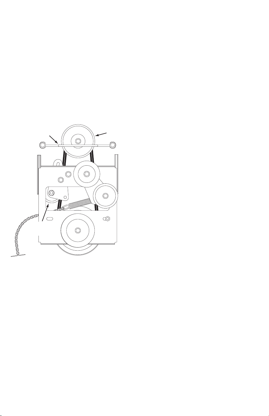
BELT ROUTING DIAGRAM
ENGINE PULLEY
SETTING THE AUGER BELT TENSION
Step 1: (Fig. 64)
1. Pull the tensioning chain until it is extended out as far as
the 3/32" hairpin cotter installed in the chain will allow.
Install a 1/8" hairpin cotter (YY) through the chain to
secure it in the extended position.
NOTE: After pulling the chain out, check to make sure the
belt does not rub against the keeper bolts. If the belt rubs,
slightly loosen the bolts, move them as far from the pulleys
as possible, and retighten.
YY
KEEPER BOLTS
AUGER BELT
ATTACH REFLECTORS TO REAR FENDER
Step 1: (Fig. 66)
1. If your tractor is not equipped with rear reflectors,
assemble the supplied rear reflectors (A4) to the rear
fender. Place the reflectors as close to the bottom of the
fender and as far apart as the shape of the fender will
allow.
SETTING THE SNOW THROWER LIFT HEIGHT
Step 1: (Fig. 65)
1. Adjust the nut on the lift link found on each side of the
snow thrower, so that the auger housing is level when
raised, and the scraper plate has approximately 3" to 4"
of ground clearance.
3"- 4"
SCRAPER PLATE
NYLOCK NUT
LIFT LINK
A4
Fig. 64
Fig. 65
Fig. 66
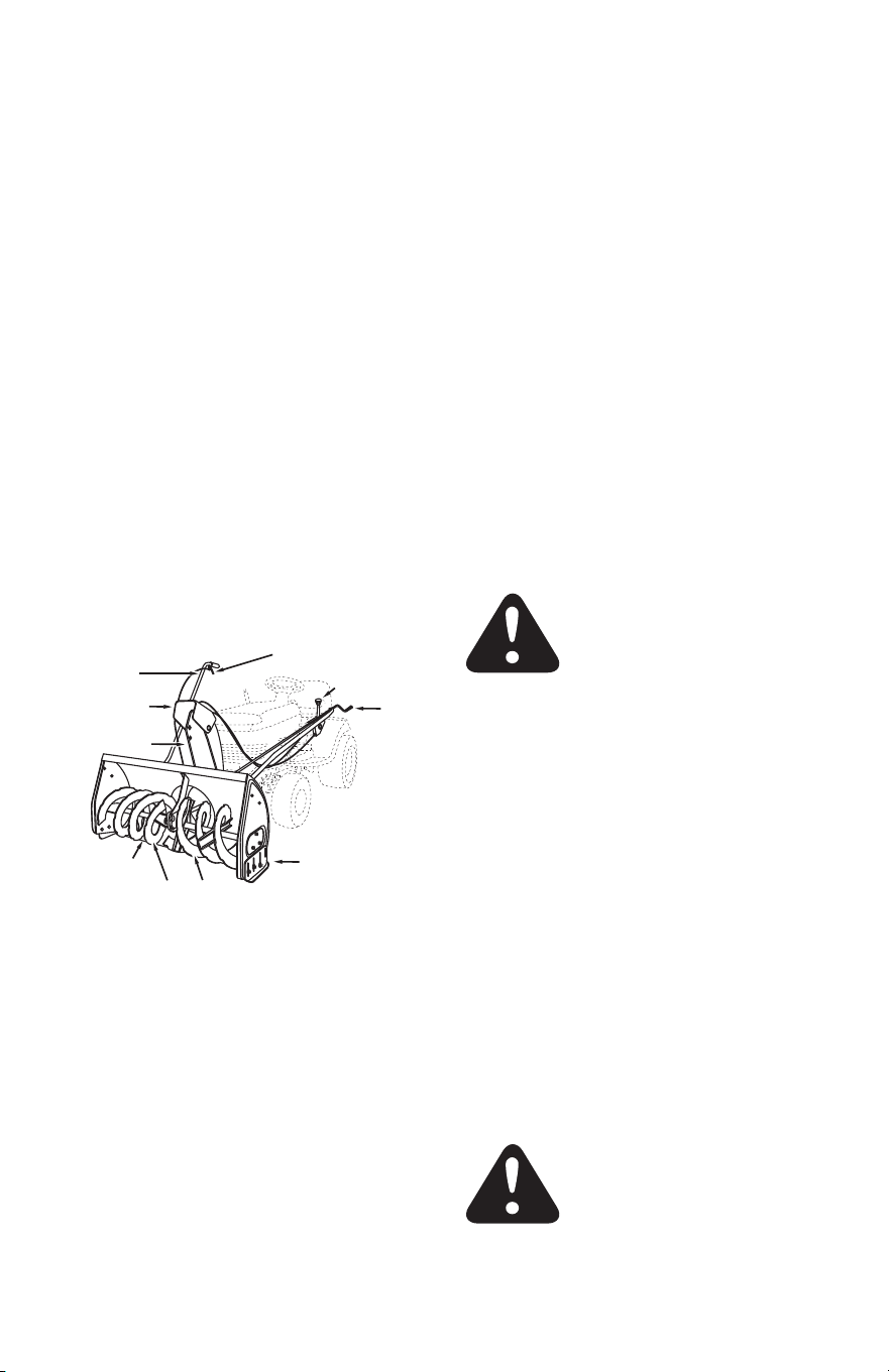
25
CHECKLIST
Before you operate your snow thrower, please review
the following checklist to help ensure that you will
obtain the best performance from your snow thrower
1. All assembly instructions have been completed with all
bolts and nuts properly tightened.
2. Check the engine belt and the auger belt. Make sure
they are routed properly around pulleys and inside all
belt keepers.
3. Check discharge chute for proper rotation.
4. Check operation of tilt control for upper chute.
5. Verify that the lift handle will lock into and release from
the raised transport position. (Refer to the Service and
Adjustments section.)
6. Check skid shoe adjustment. (Refer to the Service and
Adjustments section.)
LIFT
HANDLE
LIFT RELEASE TRIGGER
CRANK
ROD
CHUTE TILT
HANDLE
UPPER CHUTE
LOWER CHUTE
SPIRAL AUGERS, R.H. & L.H.
SKID SHOE
SCRAPER
PLATE
OPERATION
Know your Snow Thrower
Read this owner's manual and safety rules before operating
your snow thrower.
Compare the illustration below with your snow thrower
to familiarize yourself with the various controls and their
locations.
CHUTE TILT HANDLE: Pivots the Upper Chute up or
down to control the angle and distance of discharge.
CRANK ROD: Rotates the Lower and Upper Chutes to
control the direction of discharge.
LIFT HANDLE: Used to lift or lower the snow thrower
to transport or operating position.
LIFT RELEASE TRIGGER: Releases the lock which
holds the snow thrower in the transport position
UPPER AND LOWER DISCHARGE CHUTE: Controls
direction and height of snow discharge.
SCRAPER PLATE: Replaceable plate that absorbs
wear and impact from contact with ground.
SKID SHOE: Controls amount of clearance between
the scraper plate and the ground.
SPIRAL AUGER, R.H. & L.H.: Feed snow to the
impeller fan at the center of the housing.
BEFORE STARTING
1. Use the end of assembly checklist to verify that all
instructions have been properly completed.
2. Make sure the skid shoes are adjusted to maintain
adequate ground clearance between the snow thrower
and the type of surface to be cleared. (Refer to the
Service and Adjustments section).
3. Make sure the tractor engine has the correct oil for
winter operation (SAE 5W-30). Refer to tractor owner's
manual.
HOW TO START YOUR SNOW THROWER
1. The tractor should be sitting with the engine running at
full throttle. Move the attachment clutch to the engaged
position, starting the snow thrower before the tractor
clutch is engaged.
HOW TO STOP YOUR SNOW THROWER
1. To stop the snow thrower, disengage the tractor's
attachment clutch lever for manual clutches or the
clutch switch for electric clutches. Refer to your tractor
owner's manual.
HOW TO USE YOUR SNOW THROWER
CAUTION: Never direct discharge towards
bystanders or windows. Do not allow anyone
in front of unit.
Controlling Snow Discharge
1. To control the direction snow is thrown, the discharge
chute has 180 degrees of rotation. Turn the crank rod
clockwise to rotate the chute to the left. Turn the crank
rod counterclockwise to rotate the chute to the right.
2. To control the distance snow is thrown, the upper
section of the discharge chute pivots up and down.
Push forward on the chute tilt handle to pivot the chute
down, decreasing the distance snow is thrown. Pull
back on the handle to pivot the chute up, increasing the
distance snow is thrown.
Raising and Lowering
1. To raise, push down on the lift handle until the snow
thrower locks in the raised transport position.
2. To lower, push down slightly on the lift handle and pull
the trigger. With the trigger pulled, slowly lower the
snow thrower until it reaches the ground.
CAUTION: Do not operate the snow thrower
without the rear weight attached to the
tractor to provide extra traction and stability.

26
Removing Snow
Snow removal conditions vary greatly from light fluffy
snowfall to wet heavy snow. Operating instructions must be
flexible to fit the conditions encountered. The operator must
adapt the lawn tractor and snow thrower to depth of snow,
wind direction, temperature and surface conditions.
1. Before beginning operation, thoroughly inspect the area
of operation and remove all door mats, sleds, boards,
wires and other foreign objects.
2. The spiral auger speed is directly related to engine
speed. For maximum snow removal and discharge,
maintain high engine r.p.m. (full throttle). It is advisable
to operate the lawn tractor at a slow ground speed (1st
gear) for safe and efficient snow removal.
3. In deep, drifted or banked snow it will be necessary to
use full throttle and a slow ground speed (1st gear).
Drive forward into the snow, depress the tractor's
clutch-brake pedal and allow the spiral auger to clear
the snow. Repeat this method until a path is cleared.
On the second pass, overlap the first enough to allow
the snow thrower to handle the snow without repeated
stopping and starting of forward motion.
4. In extremely deep snow, raise the snow thrower from
the ground to remove the top layer and drive forward
only until the tractors front tires reach the uncleared
bottom layer of snow. Depress the tractor's clutch-brake
pedal and allow the spiral auger to clear the snow.
Reverse the tractor and lower the snow thrower to the
ground. Drive the tractor forward until the snow again
becomes too deep. Repeating this process into and out
of drifts will eventually clear even the deepest of snow
piles.
5. If the snow thrower becomes clogged with snow or
jammed with a foreign object, disengage the snow
thrower immediately and shut off the tractor engine.
Unclog the snow thrower before resuming operation.
DANGER: Shut off engine and disengage
snow thrower before unclogging discharge
chute. Unclog using a wooden stick, not
your hands.
Operating Tips
1. Discharge snow down wind whenever possible.
2. To help prevent snow from sticking to the snow thrower,
allow the snow thrower to reach outdoor temperature
before using it. A light coat of wax may also be applied
to the inside surface of the snow thrower housing and
discharge chute.
3. Use tire chains to improve traction.
4. Use rear wheel weights to improve traction.
5. Before the first snowfall, remove all stones, sticks and
other objects which could become hidden by the snow.
Permanent obstacles should be marked for visibility.
6. Overlap each pass slightly to assure complete snow
removal.
27
MAINTENANCE
Customer Responsibilities
Read and follow the maintenance schedule and the
maintenance procedures listed in this section.
Lubrication
1. Oil all pivot points on the snow thrower.
2. Oil the pivot points of the two idler arms on the clutch/
idler assembly.
3. Apply penetrating oil to the control cables of the
discharge chute.
4. Apply a good grade of spray lubricant to the trigger
assembly and the chute tilt control assembly.
Check Scraper and Shoes For Wear
Refer to figures 67 and 68
1. The scraper plate and skid shoes on the bottom of the
snow thrower are subject to wear. To prevent damage to
the spiral auger housing, replace plate and shoes before
wear is excessive.
MAINTENANCE
Storage Recommendations
1. Lower the snow thrower to the ground.
2. Remove the snow thrower from the tractor.
3. Clean the snow thrower thoroughly. Wash off any salt
deposit which may have dried on the thrower and
housing.
4. Any bare metal that has become exposed should be
painted or coated with a light oil to prevent rust.
5. Store in a dry place.
Removing the Spiral Auger Housing
Refer to figures 67 and 68
1. Lower the snow thrower to the ground.
2. Remove the clevis pins. See figure 61.
3. Lock the snow thrower's lift handle in the down position
to decrease belt tension.
4. Release the spring tension from the auger belt idler arm
on the bottom of the clutch/idler assembly.
5. Remove the auger drive belt from the clutch/idler
assembly. See figure 63.
6. Pull the spiral auger housing assembly off of the tractor.
Parts to Remove at End of Season
1. Remove the clutch/idler assembly. (The two hanger
brackets and the two shoulder bolts may be left
attached to the tractor frame.)
2. Remove the drive belt from the engine pulley.
3. If you replaced the engine pulley keeper on a manual
attachment clutch tractor, reinstall the tractor's original
engine pulley keeper. See figure 33 or figure 39.
Fill in dates as you
complete regular service.
Before each use
After each use
Service Dates
Every season
Before storage
Check for loose fasteners X
Check for worn or damaged parts X
Clean Blade X X
Lubricate Blade X
MAINTENANCE SCHEDULE
4. If you have a rod operated attachment clutch, remove
the engagement rod from the tractor's clutch arm. See
figure 29.
5. If a front mounted attachment is to be used, remove the
side plates from the tractor. Be sure to assemble bolts
back into the empty holes in the tractor frame.
28
SERVICE AND ADJUSTMENTS
CAUTION: Before servicing or adjusting the
snow thrower, shut off the engine, remove
the spark plug wire(s), set the parking brake
and remove the key from the tractor ignition.
Replacing Auger Belt
1. Disengage the tractor's attachment clutch.
2. Lower the snow thrower to the ground.
3. Remove the clevis pins. See figure 61.
4. Lock the snow thrower's lift handle in the down position
to decrease belt tension.
5. Release the spring tension from the auger belt idler arm
on the bottom of the clutch/idler assembly.
6. Remove the auger drive belt from the clutch/idler
assembly and from the spiral auger housing.
7. Install new belt over top of large auger drive pulley and
under the two side idler pulleys. Twist the belt 1/4 turn
to seat the "V" of the belt in the groove of each idler
pulley. Refer to figure 62.
8. Assemble the belt onto the clutch/idler assembly.
Skid Shoe Adjustment
1. The skid shoes are mounted on each side of the spiral
auger housing. They regulate the distance the scraper
plate is raised above the plowing surface. When
removing snow from a gravel driveway or and uneven
surface, it is advisable to keep the scraper plate as
high above the surface as possible to prevent possible
damage to the spiral auger. On blacktop or concrete
surface, keep the scraper plate as close to the surface
as possible.
2. Raise the snow thrower off the ground and place a block
under each end of the scraper plate. Loosen the six hex
nuts securing the skid shoes to the housing. Adjust the
skid shoes up or down and retighten the nuts securely.
Adjust both skid shoes to the same height to keep the
housing and the scraper plate level. See figure 67.
SKID
SHOE
Lift Release Cable Adjustment
1. If the lift rod does not lock the snow thrower securely in
the transport position, loosen the upper hex nut on the
lift bracket a few turns and tighten the lower hex nut.
Refer to figure 54.
2. If the lift rod fails to unlock completely to lower the
snow thrower, loosen the lower hex nut on the lift
bracket a few turns and tighten the upper hex nut. Refer
to figure 54.
Clutch Disengagement Adjustment
(For tractors with engagement rod clutches only.
Not for electric clutches or cable clutches).
If the spiral auger on the snow thrower does not stop when
the attachment clutch lever on the tractor is disengaged,
then adjustment is necessary. Proceed as follows. Refer back
to figure 33.
1. Place the attachment clutch lever in the disengaged
position.
2. Remove the hairpin cotter from the engagement rod
trunnion and lift the trunnion out of the hole in the idler
arm.
3. Screw the trunnion a few turns towards the front end
of the rod.
4. Replace the trunnion into the hole in the idler arm and
secure it with the hairpin cotter.
5. Check the operation of the snow thrower. If the spiral
augers still do not stop, repeat the above steps until the
augers stop when the attachment clutch lever is placed
in the disengaged position.
Spiral Auger
1. The spiral augers are secured to the auger shaft with
two shear bolts and nylock nuts. If you hit a foreign
object or if ice jams the augers, the snow thrower is
designed so that the bolts will shear.
2. If the augers will not turn, check to see if the shear bolts
have sheared. See figure 68. Two replacement shear
bolts and nylock nuts have been provided with the
snow thrower. For future use order part number 42489
shear bolt and number 47810 nylock nut.
GEAR HOUSING
SHEAR BOLT AND
HEX LOCK NUT
SCRAPER
PLATE
SKID
SHOE
Fig. 67
Fig. 68

29
Adjusting Lift Height, Leveling
The snow thrower is equipped with two threaded lift links
for adjusting the lift height and leveling of the snow thrower
in the raised position.
To Adjust the Lift Height
Refer to figure 65
1. Raise the snow thrower to the highest position.
2. Lower the snow thrower to the ground.
3. Check the clearance between the rear of the idler
bracket (item 39) and the lift shaft assembly (item 1).
A minimum 1/16" clearance in the raised position is
necessary to avoid possible damage to the lift system.
4. To increase the lift height, tighten the nuts on the top of
both lift links equally until 3" to 4" of ground clearance
is obtained. The maximum clearance is approximately
4inches for GT tractors and 3 inches for YT tractors.
To Level When Raised
Refer to figure 65
1. To make the snow thrower level when it is in the raised
position, adjust the nut on the top of the lift link on
one side of the snow thrower until the snow thrower
is approximately level. It is not critical that the snow
thrower be exactly level in the raised position, it will
level out when it is lowered to the ground.
Problem Cause Correction
Spiral Augers don’t turn 1. Upper or lower V belt too loose
2. Upper or lower V belt broken
3. Shear bolts are sheared.
1. Increase tension on V belt
2. Replace V belt
3. Replace shear bolts
Clogged Discharge Chute 1. Tractor ground speed too fast
2. Tractor throttle set too low
3. Snow too deep
4. Snow melts during contact with
the snow thrower
1. Use lower tractor gear
2. Increase to full throttle
3. Raise the snow thrower
4. Allow snow thrower to cool to
outdoor temperature before
using
Snow Thrower Stalls Tractor Engine 1. Object jammed in Spiral Auger
2. Hard or heavy snow
1. Stop engine, disengage the
snow thrower clutch and clear
the auger
2. Increase to full throttle and
decrease ground speed
Front wheels slide instead of steering 1. Not enough traction at front
wheels
1. Increase scraper plate clearance
by lowering skid shoes
2. Pull down on lift handle to
increase weight on front wheels
Snow thrower rides up over snow 1. Tractor ground speed too fast
2. Bottom snow is icy or hard
packed
1. Reduce ground speed
2. Lower the skid shoes so that
front of skid shoe is lower than
the rear.
TROUBLESHOOTING
30
11
12
7
3
28
29
5
2
6
35
23
30
35
9
46
38
8
47
23
55
55
4
1
32
49
10
44
56
42
54
27
27
34
36
19
23
24
30
37
43
43
40
40
21
46
17
45
52
50
53
19
23
13
30
23
30
8
23
15
23
23
23
30
17
23
51
48
41
20
22
14
26
18
20
58
57
30
37
22
33
21
39
31
34
14
20
25
16
16
25
13
17
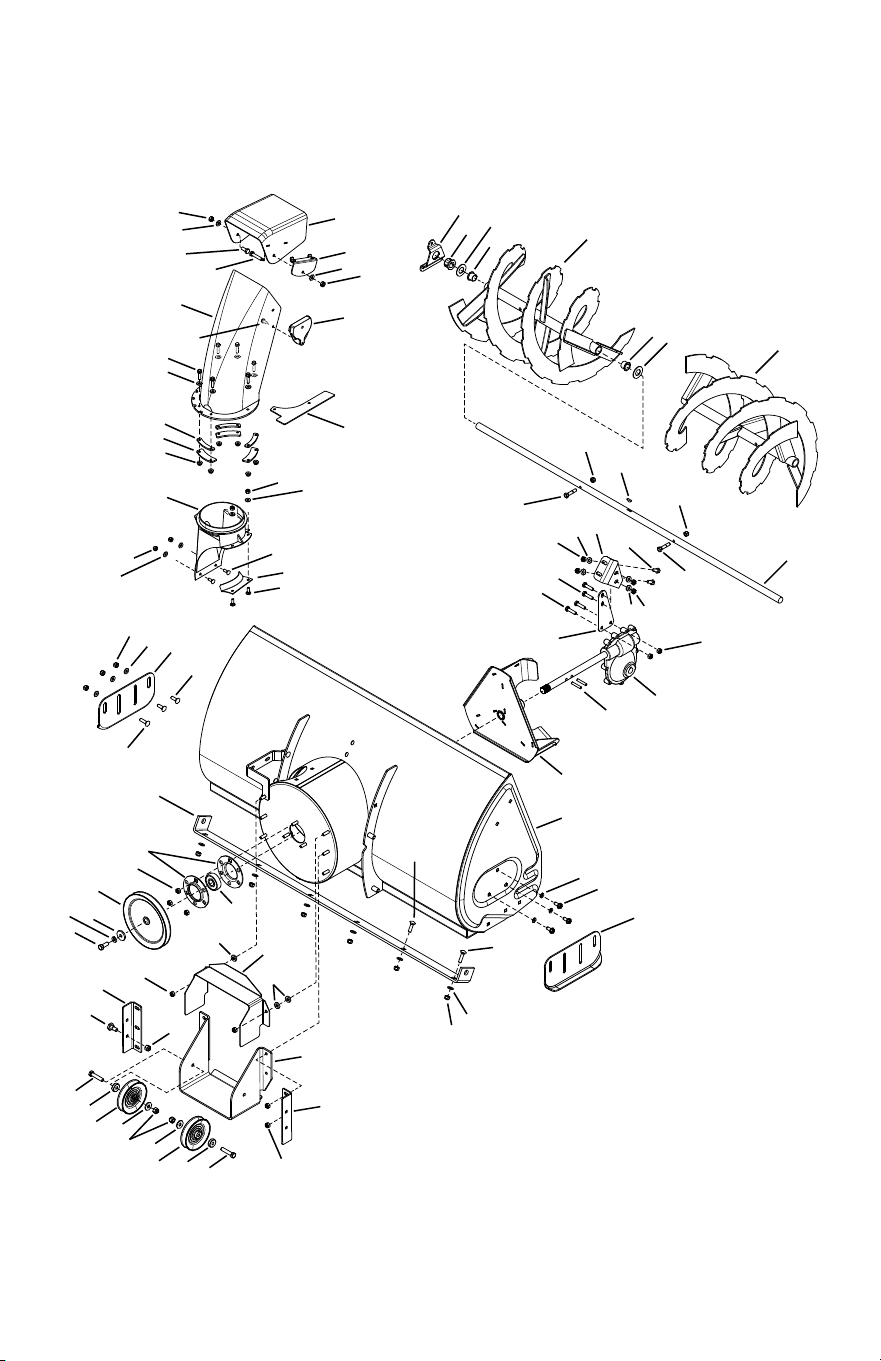
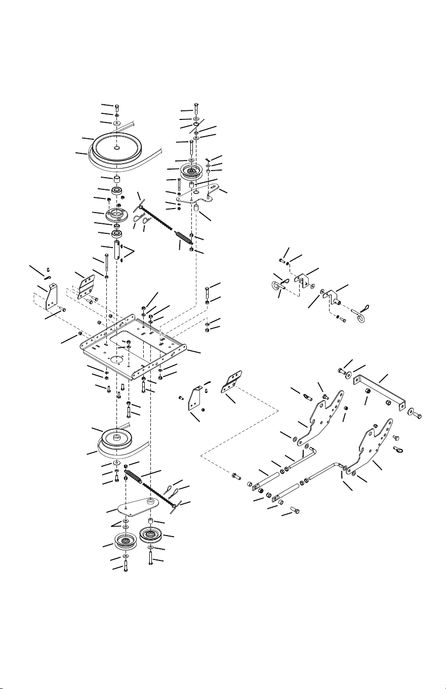
Parts
Repair Parts for Model 486.248374 42" Snow Thrower
To purchase repair parts, call the following toll-free number:
1-888-331-4569

31
Ref. Part No Qty Description
1 28237 2 Flange, Bearing
2 67629BL3 1 Housing Assembly
3 71464 1 Gear Assembly
4 47026 1 Pulley, V Type
5 69823BL3 1 Impeller Assembly
6 24773BL3 1 Scraper Plate
7 25982 1 Shaft, Auger Gearbox
8 27508BL1 2 Bracket, Down Stop
9 24816BL3 1 Cover, Belt
10 27510BL1 1 Chute Reinforcement
11 67689BL3 1 Auger Assembly, L.H.
12 67688BL3 1 Auger Assembly, R.H.
13 43063 4 Bolt, Hex 5/16”-18 x 1”
14 44950 4 Carriage Bolt, 1/4”-20 x 3/4”
15 HA20185 1 #61 Woodru Key
16 44326 4 Carriage Bolt, 5/16”-18 x 1” Lg.
17 43080 12 Carriage Bolt, 5/16”-18 x
3/4” Lg.
18 47630 6 Bolt, Self-Tap 5/16”-18 x
1-1/2”
19 42849 2 Bolt, Shear 5/16”-18 x 1-1/2”
20 43088 10 Washer, 1/4”
21 43070 2 Washer, 3/8”
22 47189 4 Hex Nut, 1/4”-20 Nylock
23 47810 29 Hex Nut, 5/16”-18 Nylock
24 41625 2 Spiral Pin, 1/4” x 1-1/2” Lg.
25 42846 3 Bushing
26 43086 6 Lock Washer, 5/16”
27 43009 6 Washer, .785” x 1.57” x .057”
28 27915BL3 1 Brace, Gearbox Top
29 27916BL3 1 Brace, Gearbox Lower
30 43081 18 Washer, 5/16” Std. Wrt.
Ref. Part No Qty Description
31 47615 2 Bearing, Flange
32 42844 1 Bearing, Ball
33 43182 1 Hex Bolt, 5/16”-18 x 3/4”
34 741-0493C 4 Bearing, Split, 3/4”
35 24279BL1 2 Skid Shoe
36 27458BL1 2 Flange, Bearing
37 43064 2 Nut, Hex 5/16”-18 Loc 2-Way
38 27502BL3 1 Bracket, Idler
39 48106 4 Bolt, Shoulder
40 41576 2 Hex Bolt, 3/8”-16 x 1-3/4”
41 44377 1 Hex Bolt, 3/8”-24 x 1”
42 27584BL1 1 Bracket, Cable
43 42850 2 Spacer
44 27809 3 Chute Keeper
45 27810 3 Chute Spacer
46 HA21362 4 Hex Nut, 3/8”-16 x 1”
47 27509BL1 1 Bracket, Chute Anti-Rotation
48 43003 1 Lock Washer, 3/8”
49 27505 1 Chute Adapter
50 43661 6 Hex Bolt, 1/4”-20 x 1”
51 42828 1 Washer
52 47598 6 Hex Lock Nut, 1/4” Flanged
53 41620 1 Chute, Upper
54 42834 1 Guide, Cable
55 47044 2 Pulley, V Type 4”
56 41621 1 Chute, Lower
57 43085 1 Hex Bolt, 5/16”-18 x 1-1/2”
58 41622 1 Screw, 1/4”-14 x 5/8”
59 3-218 1 Owner’s Manual
32
1
5
5
3
3
4
5
5
2
5
5
2
7
59
60
7
8
10
10
11
11
12
12
14
15
15
16
16
25
23
23
38
58
52
43
47
46
38
38
35
36
39
33
40
41
28
37
42
45
44
48
49
6
16
52
52
54
53
34
46
17
47
65
51
51
4
31
29
30
51
32
51
30
13
21
22
19
24
27
20
52
18
55
56
26
22
9
7
50
60
50
56
57
9
55
13
59
57
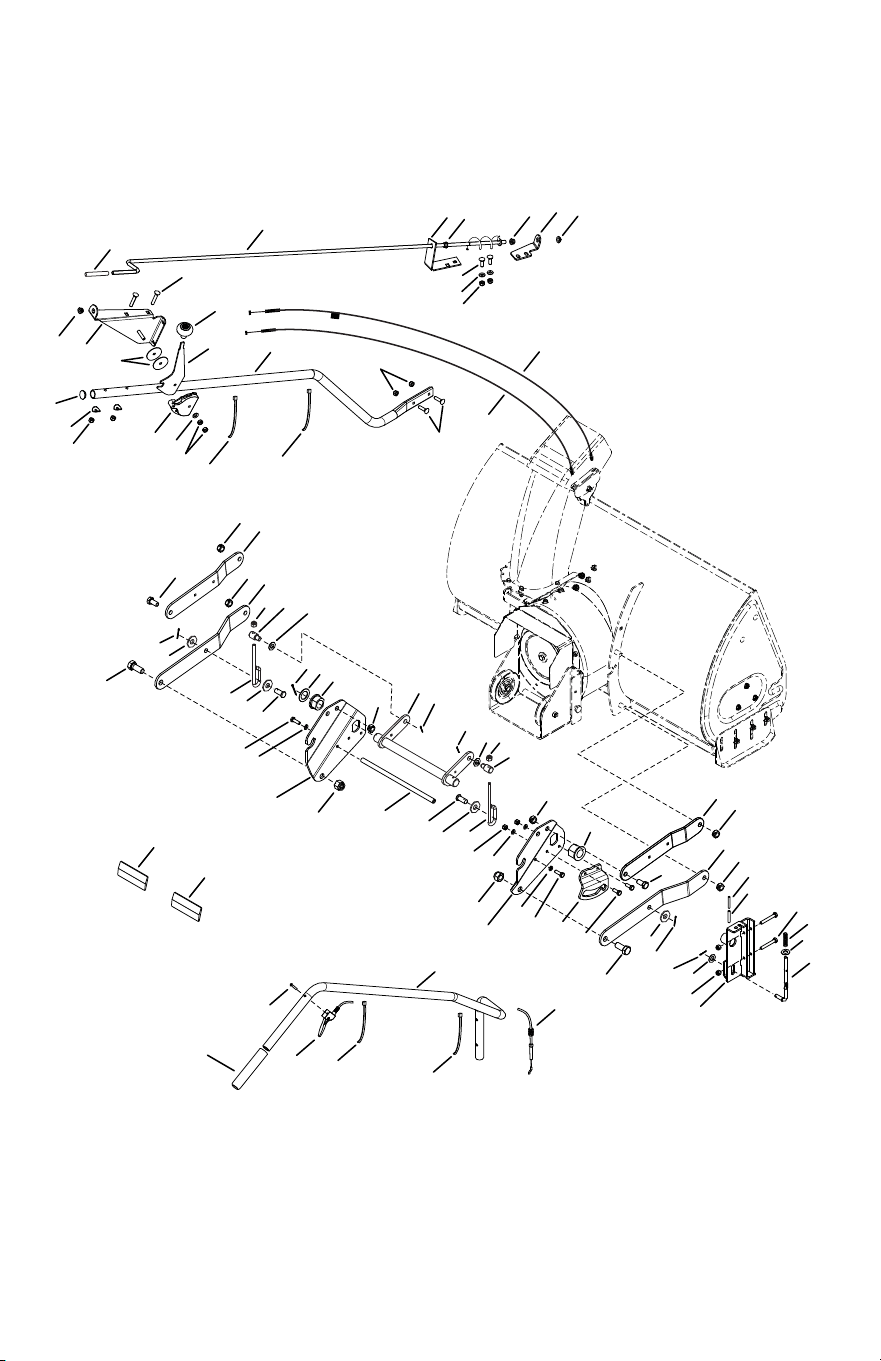
Parts
Repair Parts for Model 486.248374 42" Snow Thrower
To purchase repair parts, call the following toll-free number:
1-888-331-4569

33
Ref. Part No Qty Description
1 68550BL3 1 Lift Shaft Assembly
2 41616 2 Hex Bolt, 1/2”-13 x 1”
3 41614 2 Hex Bolt, 5/8”-11 x 1-1/2”
4 41615 2 Nut, Hex Lock 5/8”-11 Thread
5 43262 6 Nut, Hex Lock 1/2”-13
6 43601 1 Washer, 1.59” x 1.032” x .060”
7 142 3 Pin, Cotter 1/8” x 3/4”
8 43093 1 Pin, Cotter 1/8” x 1-1/2”
9 R19171616 2 Washer, 17/32” x 1”
10 42939 2 Bearing, Flange with Flats
11 27753BL3 2 Link, 15.80” Long
12 27752BL3 2 Link, 11.75” Long
13 41807 2 Rod Lift
14 24311 1 Rod, Spacer
15 47599 2 Hex Bolt, 5/16”-18 x 1”
(Locking)
16 43086 4 Lock Washer, 5/16”
17 24820BL1 1 Bracket, Lift
18 67784BL3 1 Assembly, Handle Lift Bracket
19 48049 1 Rod, Index Lift
20 47369 1 Pin, Spring 3/16” x 1-3/4”
21 42955 1 Spring Compression
22 R19131316 2 Washer, 13/32” x 13/16”
23 47788 2 Reector, Rear
24 43084 2 Hex Bolt, 5/16”-18 x 1-3/4”
25 43182 2 Hex Bolt, 5/16”-18 x 3/4”
26 43572 2 Washer, .342” x 1.5” x .059”
27 47368 1 Pin, Spring 5/16” x 1-3/4”
28 42215 2 Carriage Bolt, 5/16”-18 x
1-3/4”
29 49916BL3 1 Tube, Lift Handle
30 49912 1 Trigger and Lift Cable
Assembly
Ref. Part No Qty Description
31 49266 1 Screw, Oval #10-24 x 1-1/2”
32 44482 1 Grip, Handle
33 27914BL3 1 Tube, Crank Rod Support
34 24393BL1 1 Bracket, Chute Crank
35 27708BL1 1 Bracket, Chute Crank
36 HA9822 1 Grip
37 44917 1 Palnut, 3/8”
38 42839 3 Bushing, 3/8” Plastic
39 68225BL3 1 Assembly, Chute Crank Rod
40 27585BL1 1 Handle, Chute Tilt
41 42833 1 Knob
42 68405BL3 1 Assembly, Chute Tilt Bracket
43 42834 1 Guide, Cable
44 42835 1 Cable, Chute Control
45 42836 1 Cable, Chute Control with
Clip
46 43064 4 Nut, Hex Lock 5/16”-18
47 43081 3 Washer, 5/16”
48 24285BL1 1 Plate, Mounting (L.H.)
49 24284BL1 1 Plate, Mounting (R.H.)
50 R19172410 2 Washer, 1/2”
51 726-0178 4 Tie, Nylon
52 47810 6 Nut, Nylock Hex 5/16”-18
53 43682 2 Carriage Bolt, 5/16”-18 x
1-1/4”
54 44695 2 Washer, Bowed
55 44062 2 Pin, Clevis 1/2” x 1”
56 24807 2 Trunnion, Lift
57 HA21362 2 Nut, Nylock Hex 3/8”-16
58 42991 1 Plug
59 43010 2 Pin, 1/8” x 1-1/4”
60 1540-59 2 Washer, .52” x 1.062” x .09”
34
2
3
4
22
23
17
24
11
16
21
19
19
14
29
3
63
53
44
64
66
67
61
62
55
57
20
15
31
47
34
1
50
51
52
51
40
37
34
45
13
24
17
23
12
35
9
34
1
34
31
33
28
36
40
34
30
68
42
60
58
59
60
21
56
57
65
63
54
6
10
10
12
69
48
2
43
49
70
5
71
25
31
17
17
12
18
36
35
12
8
12
17
12
17
17
7
38
39
41
46
34
32
26
27
30
30
10
10
10
37
Parts
Repair Parts for Model 486.248374 42" Snow Thrower
To purchase repair parts, call the following toll-free number:
1-888-331-4569
This parts diagram if for the tractor frame mentioned on
pages 5-9.

35
Ref. Part No Qty Description
1 48883 2 Pulley, Flat 3-5/8”
2 43063 9 Hex Bolt, 5/16-18 x 1”
3 43083 2 Hex Nut, 5/16”-18
4 43086 2 Lock Washer, 5/16”
5 43081 2 Washer, 5/16” Std. Wrt.
6 26943BL3 1 Frame, Clutch and Pulley
7 63904BL1 1 Idler Arm Assembly
8 24286 1 Spacer, Pivot
9 63762BL1 1 Idler Bracket Assembly
10 43015 5 Hex Nut, 3/8”-16
11 46981 1 Pulley, V Type 9”
12 43082 9 Nut, Hex Lock, 3/8”-16
13 46982 1 Pulley, V Type, 5-1/2”
14 27582 1 Shaft
15 42830 1 Spacer
16 42831 1 Spacer
17 43003 7 Lock Washer, 3/8”
18 42827 2 Key
19 42829 2 Bearing, Ball
20 27781BL1 1 Housing, Bearing
21 47810 9 Hex Nut, 5/16”-18 Nylock
22 43182 4 Hex Bolt, 5/16”-18 x 3/4”
23 44377 2 Hex Bolt, 3/8”-24 x 1”
24 42828 2 Washer
25 25722BL1 1 Brace Frame
26 46989 1 Belt, V Type Drive (55”)
– 41353 1 Belt, V Type Drive (52”)
(Not shown)
27 42992 1 Belt, V Type Auger
28 47044 1 Pulley, V Type 4”
29 47025 1 Hex Bolt, 5/16”-18 x 3-1/2”
30 43432 3 Hex Bolt, 3/8”-16 x 2-1/2”
31 43054 3 Hex Bolt, 3/8”-16 x 2”
32 24571 1 Spacer
33 24472 1 Spacer, Pivot
34 43070 7 Washer, 3/8”
35 46959 2 Spring
Ref. Part No Qty Description
36 46963 2 Chain
37 43055 2 Pin, Hair Cotter, 3/32”
38 23727 1 Spacer
39 43088 1 Washer, 1/4”
40 43343 2 Pin, Hair Cotter #4 (1/8”)
41 HA3090 2 Pin, Hair Cotter 5/64”
42 43038 2 Pin, Pivot Lock 3/8 X 1-1/2
43 43086 2 Washer, Loc 5/16
44 41352BL1 2 Tube, Support
45 47607 1 Spring, Torsion
46 23625 1 Spacer
47 43509 1 Hex Bolt, 3/8”-16 x 2-2/4” Lg.
48 R19172410 2 Washer, .531 X 1.5 X .134
49 43343 2 Pin, Hair Cotter 3/32 X 2-5/1
50 49870 1 Hex Bolt, 1/4”-20 x 2-1/2”
51 43178 2 Hex Nut, 1/4”-20
52 43177 1 Lock Washer, 1/4”
53 27011BL1 1 Bracket, Front Frame LH
54 27010BL1 1 Bracket, Front Frame RH
55 67267BL1 1 Ass’y, Rear Mtg Brkt LH
56 67266BL1 1 Ass’y, Rear Mtg Brkt RH
57 47134 4 Pin, Hair Cotter .08 X 1.58
58 43020 2 Bolt, Hex 1/2-13 X 1-1/2 GR5
59 27231 2 Spacer, .530 ID X .750 X .50
60 41657 4 Nut, Hex 1/2-13 Nyloc
61 43019 4 Nut, Hex 1/2-13 Jam
62 41346 2 Link, Support
63 R19171616 4 Washer, .531 X 1 X .059
64 67269BL1 1 Ass’y, Front Mtg Plate LH
65 67268BL1 1 Ass’y, Front Mtg Plate RH
66 42847 2 Pin, Quick Release 1/2” Dia
67 48106 2 Bolt, Shoulder
68 HA21362 2 Nut, Hex 3/8-16 Nyloc
69 43351 2 Bolt, Hex 1/2-13 X 1-1/4 Gr5
70 67053BL1 1 Hanger Bracket Assembly LH.
71 67052BL1 1 Hanger Bracket Assembly RH
36
2
3
4
22
22
23
17
24
11
16
21
19
19
14
29
3
25
5
53
20
15
31
47
34
1
50
51
52
51
40
37
34
45
13
24
17
23
12
35
9
34
1
60
22
58
43
34
31
33
28
36
40
34
30
21
44
53
44
25
6
10
10
2
54
55
56
57
57
61
59
48
49
42
56
58
55
62
54
63
12
31
17
17
12
18
36
35
12
8
12
17
12
17
17
7
38
39
41
46
34
32
5
26
27
30
30
10
10
10
37
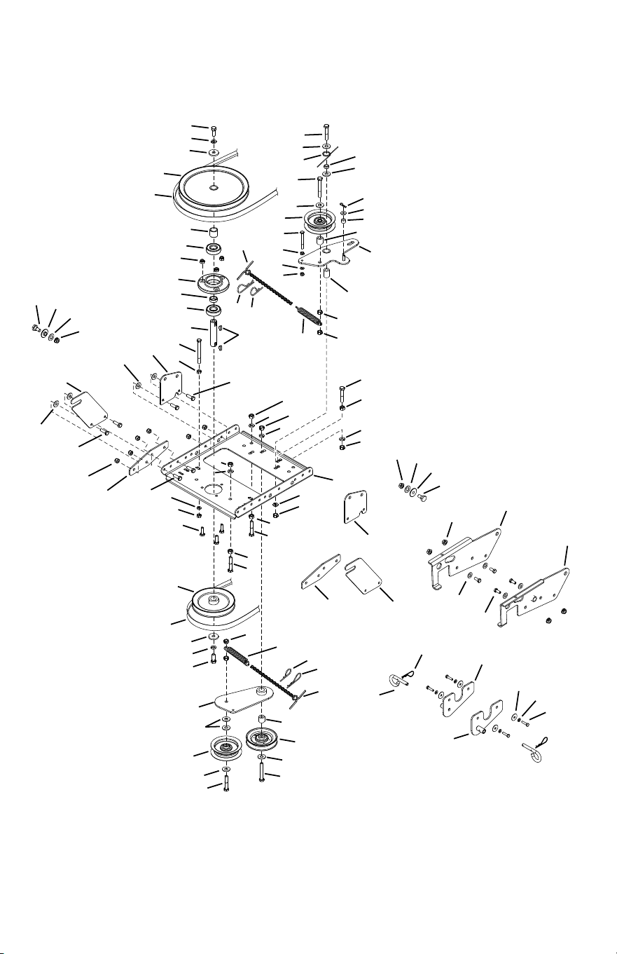
Parts
Repair Parts for Model 486.248374 42" Snow Thrower
To purchase repair parts, call the following toll-free number:
1-888-331-4569
This parts diagram if for the tractor frame mentioned on
pages 10-13.

37
Ref. Part No Qty Description
1 48883 2 Pulley, Flat 3-5/8”
2 43063 9 Hex Bolt, 5/16-18 x 1”
3 43083 2 Hex Nut, 5/16”-18
4 43086 2 Lock Washer, 5/16”
5 43081 20 Washer, 5/16” Std. Wrt.
6 26943BL3 1 Frame, Clutch and Pulley
7 63904BL1 1 Idler Arm Assembly
8 24286 1 Spacer, Pivot
9 63763BL1 1 Idler Bracket Assembly
10 43015 5 Hex Nut, 3/8”-16
11 46981 1 Pulley, V Type 9”
12 43082 9 Nut, Hex Lock, 3/8”-16
13 46982 1 Pulley, V Type, 5-1/2”
14 27582 1 Shaft
15 42830 1 Spacer
16 42831 1 Spacer
17 43003 7 Lock Washer, 3/8”
18 42827 2 Key
19 42829 2 Bearing, Ball
20 27781BL1 1 Housing, Bearing
21 47810 11 Hex Nut, 5/16”-18 Nylock
22 43182 8 Hex Bolt, 5/16”-18 x 3/4”
23 44377 2 Hex Bolt, 3/8”-24 x 1”
24 42828 2 Washer
25 27016BL1 2 Front Pulley Frame Bracket
26 46989 1 Belt, V Type Drive (55”)
– 41353 1 Belt, V Type Drive (52”)
(Not shown)
27 42992 1 Belt, V Type Auger
28 47044 1 Pulley, V Type 4”
29 47025 1 Hex Bolt, 5/16”-18 x 3-1/2”
30 43432 3 Hex Bolt, 3/8”-16 x 2-1/2”
31 43054 3 Hex Bolt, 3/8”-16 x 2”
32 24571 1 Spacer
33 24472 1 Spacer, Pivot
34 43070 7 Washer, 3/8”
Ref. Part No Qty Description
35 46959 2 Spring
36 46963 2 Chain
37 43055 2 Pin, Hair Cotter, 3/32”
38 23727 1 Spacer
39 43088 1 Washer, 1/4”
40 43343 2 Pin, Hair Cotter #4 (1/8”)
41 HA3090 2 Pin, Hair Cotter 5/64”
42 43343 2 Pin, Hair Cotter 3/32 X 2-5/1
43 43038 2 Pin, Pivot Lock 3/8 X 1-1/2
44 27900BL3 2 Strap, Rear Mounting Ext.
45 47607 1 Spring, Torsion
46 23625 1 Spacer
47 43509 1 Hex Bolt, 3/8”-16 x 2-2/4” Lg.
48 27901BL3 1 Plate, Front Mtg LH
49 27902BL3 1 Plate, Front Mtg RH
50 49870 1 Hex Bolt, 1/4”-20 x 2-1/2”
51 43178 2 Hex Nut, 1/4”-20
52 43177 1 Lock Washer, 1/4”
53 25728BL1 2 Rear Pulley Frame Bracket
54 48106 2 Bolt, Shoulder
55 44685 2 Spacer, Shoulder
56 R19171616 2 Washer, .531 X 1 X .059
57 47572 6 Hex Lock Nut, 3/8”-16
Flanged
58 R19131316 4 Washer, .406 X .812 X .062
59 68402BL3 1 Ass’y, Hanger Brkt. RH
60 68403BL3 1 Ass’y, Hanger Brkt. LH
61 42977 4 Washer, .28 X 1.0 X .06
62 43177 4 Washer, Loc 1/4
63 42300 4 Bolt, Hex M6 X 1 X 25
38
2
3
4
22
22
23
17
24
11
16
21
19
19
14
29
3
25
5
2
54
20
15
31
47
34
1
50
51
52
51
40
37
34
45
13
24
17
23
12
35
9
34
1
65
22
59
63
34
31
33
28
36
40
34
30
21
44
54
44
53
25
6
10
10
55
56
57
58
58
66
64
60
61
62
57
58
56
67
55
41
39
49
43
42
68
12
31
17
17
12
18
36
35
12
8
12
17
12
17
17
7
38
39
41
46
34
32
5
26
27
30
30
10
10
10
37
48
1
34
17
12
69
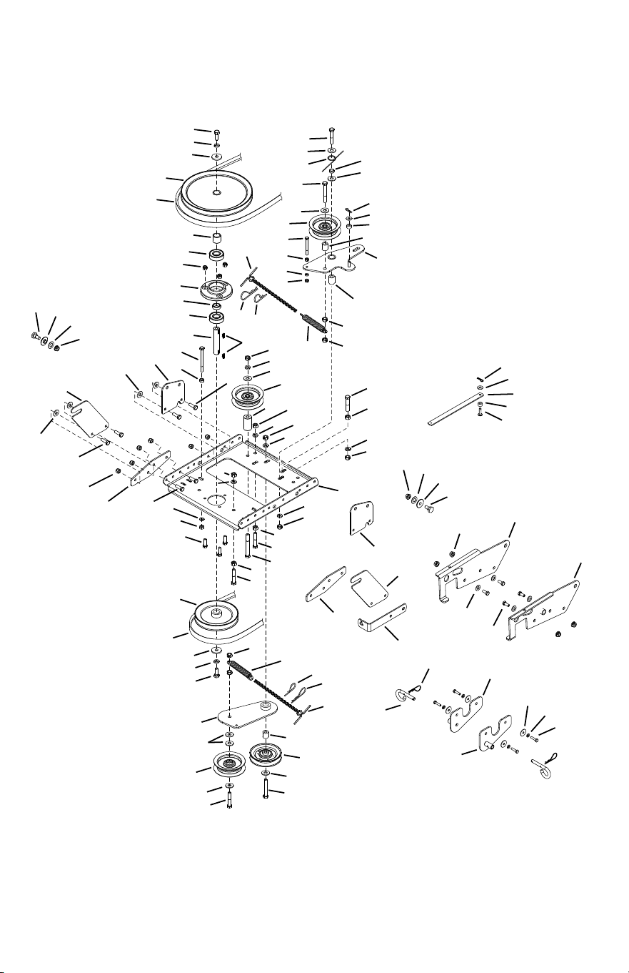
Parts
Repair Parts for Model 486.248374 42" Snow Thrower
To purchase repair parts, call the following toll-free number:
1-888-331-4569
This parts diagram if for the tractor frame mentioned on
pages 10 and 14-16.

39
Ref. Part No Qty Description
1 48883 3 Pulley, Flat 3-5/8”
2 43063 9 Hex Bolt, 5/16-18 x 1”
3 43083 2 Hex Nut, 5/16”-18
4 43086 2 Lock Washer, 5/16”
5 43081 20 Washer, 5/16” Std. Wrt.
6 26943BL3 1 Frame, Clutch and Pulley
7 63904BL1 1 Idler Arm Assembly
8 24286 1 Spacer, Pivot
9 63762BL1 1 Idler Bracket Assembly
10 43015 5 Hex Nut, 3/8”-16
11 46981 1 Pulley, V Type 9”
12 43082 10 Nut, Hex Lock, 3/8”-16
13 46982 1 Pulley, V Type, 5-1/2”
14 27582 1 Shaft
15 42830 1 Spacer
16 42831 1 Spacer
17 43003 8 Lock Washer, 3/8”
18 42827 2 Key
19 42829 2 Bearing, Ball
20 27781BL1 1 Housing, Bearing
21 47810 11 Hex Nut, 5/16”-18 Nylock
22 43182 8 Hex Bolt, 5/16”-18 x 3/4”
23 44377 2 Hex Bolt, 3/8”-24 x 1”
24 42828 2 Washer
25 27016BL1 2 Front Pulley Frame Bracket
26 46989 1 Belt, V Type Drive (55”)
– 41353 1 Belt, V Type Drive (52”)
(Not shown)
27 42992 1 Belt, V Type Auger
28 47044 1 Pulley, V Type 4”
29 47025 1 Hex Bolt, 5/16”-18 x 3-1/2”
30 43432 3 Hex Bolt, 3/8”-16 x 2-1/2”
31 43054 3 Hex Bolt, 3/8”-16 x 2”
32 24571 1 Spacer
33 24472 1 Spacer, Pivot
34 43070 8 Washer, 3/8”
35 46959 2 Spring
36 46963 2 Chain
37 43055 2 Pin, Hair Cotter, 3/32”
Ref. Part No Qty Description
38 23727 1 Spacer
39 43088 2 Washer, 1/4”
40 43343 2 Pin, Hair Cotter #4 (1/8”)
41 HA3090 3 Pin, Hair Cotter 5/64”
42 23727 1 Spacer, .310 ID X .560 OD X .36
43 63904BL1 1 Ass’y, Idler Arm (Wldm)
44 27900BL3 2 Strap, Rear Mounting Ext.
45 47607 1 Spring, Torsion
46 23625 1 Spacer
47 43509 1 Hex Bolt, 3/8”-16 x 2-2/4” Lg.
48 25780 1 Spacer
49 28414BL3 1 Strap, Cable
50 49870 1 Hex Bolt, 1/4”-20 x 2-1/2”
51 43178 2 Hex Nut, 1/4”-20
52 43177 1 Lock Washer, 1/4”
53 28413BL3 1 Bracket, Cable
54 25728BL1 2 Rear Pulley Frame Bracket
55 48106 2 Bolt, Shoulder
56 44685 2 Spacer, Shoulder
57 R19171616 2 Washer, .531 X 1 X .059
58 47572 6 Hex Lock Nut, 3/8”-16 Flanged
59 R19131316 4 Washer, .406 X .812 X .062
60 27901BL3 1 Plate, Front Mtg LH
61 27902BL3 1 Plate, Front Mtg RH
62 43343 2 Pin, Hair Cotter 3/32 X 2-5/1
63 43038 2 Pin, Pivot Lock 3/8 X 1-1/2
64 68402BL3 1 Ass’y, Hanger Brkt. RH
65 68403BL3 1 Ass’y, Hanger Brkt. LH
66 42977 4 Washer, .28 X 1.0 X .06
67 43177 4 Washer, Loc 1/4
68 42300 4 Bolt, Hex M6 X 1 X 25
69 46938 1 Hex Bolt, 3/8”-16 X 3-1/4”
40
1
2
3
4
22
49
23
17
24
11
16
21
19
19
14
29
3
63
53
44
64
66
67
61
62
55
57
20
15
31
47
34
5
50
51
52
51
40
37
34
45
13
24
17
23
12
35
9
34
5
34
31
33
28
36
40
34
30
68
74
74
60
58
70
60
21
21
56
57
65
63
54
6
10
10
2
12
69
70
73
73
25
31
17
17
12
18
36
35
12
8
12
17
12
17
17
7
38
39
41
46
34
32
26
27
30
30
10
10
10
37
77
48
59
2
43
76
21
42
41
39
72
75
71
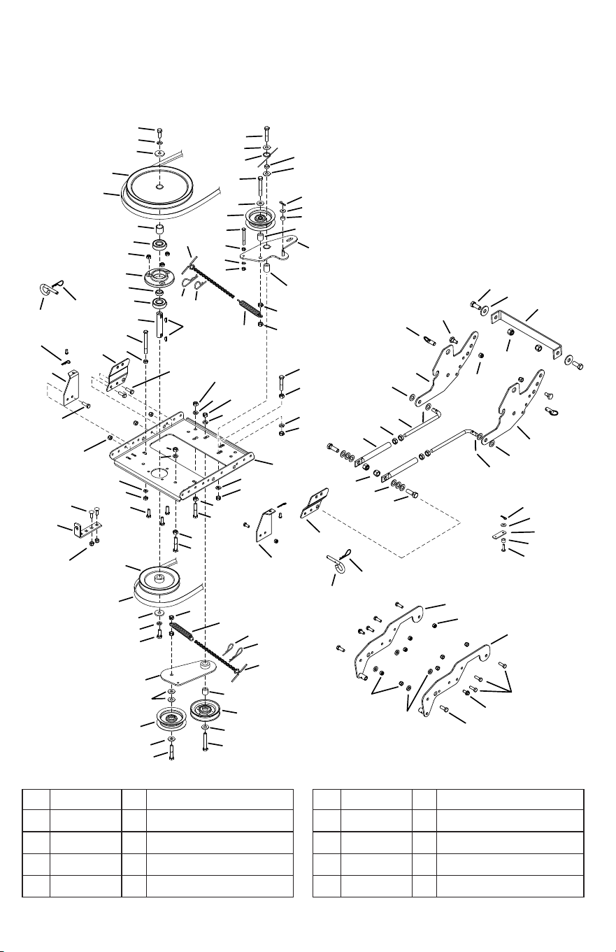
Parts
Repair Parts for Model 486.248374 42" Snow Thrower
To purchase repair parts, call the following toll-free number:
1-888-331-4569
This parts diagram if for the tractor frame mentioned on
pages 17-21.
Ref. Part No Qty Description
1 43080 2 Carriage Bolt, 5/16”-18 x 3/4”
2 43063 13 Hex Bolt, 5/16-18 x 1”
3 43083 2 Hex Nut, 5/16”-18
4 43086 2 Lock Washer, 5/16”
Ref. Part No Qty Description
5 48883 2 Pulley, Flat 3-5/8”
6 26943BL3 1 Frame, Clutch and Pulley
7 63904BL1 1 Idler Arm Assembly
8 24286 1 Spacer, Pivot

41
Ref. Part No Qty Description
9 63762BL1 1 Idler Bracket Assembly
10 43015 5 Hex Nut, 3/8”-16
11 46981 1 Pulley, V Type 9”
12 43082 9 Nut, Hex Lock, 3/8”-16
13 46982 1 Pulley, V Type, 5-1/2”
14 27582 1 Shaft
15 42830 1 Spacer
16 42831 1 Spacer
17 43003 7 Lock Washer, 3/8”
18 42827 2 Key
19 42829 2 Bearing, Ball
20 27781BL1 1 Housing, Bearing
21 47810 15 Hex Nut, 5/16”-18 Nylock
22 43182 4 Hex Bolt, 5/16”-18 x 3/4”
23 44377 2 Hex Bolt, 3/8”-24 x 1”
24 42828 2 Washer
25 25722BL1 1 Brace Frame
26 46989 1 Belt, V Type Drive (55”)
– 41353 1 Belt, V Type Drive (52”)
(Not shown)
27 42992 1 Belt, V Type Auger
28 47044 1 Pulley, V Type 4”
29 47025 1 Hex Bolt, 5/16”-18 x 3-1/2”
30 43432 3 Hex Bolt, 3/8”-16 x 2-1/2”
31 43054 3 Hex Bolt, 3/8”-16 x 2”
32 24571 1 Spacer
33 24472 1 Spacer, Pivot
34 43070 7 Washer, 3/8”
35 46959 2 Spring
36 46963 2 Chain
37 43055 2 Pin, Hair Cotter, 3/32”
38 23727 1 Spacer
39 43088 2 Washer, 1/4”
40 43343 2 Pin, Hair Cotter #4 (1/8”)
41 HA3090 3 Pin, Hair Cotter 5/64”
42 42846 4 Bushing, Pivot (Skid)
43 HA21362 2 Nut, Hex 3/8-16 Nyloc
44 41352BL1 2 Tube, Support
45 47607 1 Spring, Torsion
Ref. Part No Qty Description
46 23625 1 Spacer
47 43509 1 Hex Bolt, 3/8”-16 x 2-2/4” Lg.
48 43001 2 Bolt, Hex 3/8-16 X 1 GT5
49 24558BL1 1 Cable Mount Bracket
50 49870 1 Hex Bolt, 1/4”-20 x 2-1/2”
51 43178 2 Hex Nut, 1/4”-20
52 43177 1 Lock Washer, 1/4”
53 27011BL1 1 Bracket, Front Frame LH
54 27010BL1 1 Bracket, Front Frame RH
55 67267BL1 1 Ass’y, Rear Mtg Brkt LH
56 67266BL1 1 Ass’y, Rear Mtg Brkt RH
57 47134 4 Pin, Hair Cotter .08 X 1.58
58 43020 2 Bolt, Hex 1/2-13 X 1-1/2 GR5
59 47630 2 Bolt, Hex 5/16-18 X 3/4 St WH
60 41657 4 Nut, Hex 1/2-13 Nyloc
61 43019 4 Nut, Hex 1/2-13 Jam
62 41346 2 Link, Support
63 R19171616 4 Washer, .531 X 1 X .059
64 67269BL1 1 Ass’y, Front Mtg Plate LH
65 67268BL1 1 Ass’y, Front Mtg Plate RH
66 42847 2 Pin, Quick Release 1/2” Dia
67 48106 2 Bolt, Shoulder
68 HA21362 2 Nut, Hex 3/8-16 Nyloc
69 43351 2 Bolt, Hex 1/2-13 X 1-1/4 Gr5
70 R19172410 8 Washer, .531 X 1.5 X .134
71 23727 1 Spacer, .310 ID X .560 OD X .36
72 27340BL1 Strap, Clutch Cable Extension
73 43343 2 Pin, Hair Cotter 3/32 X 2-5/1
74 43038 2 Pin, Pivot Lock 3/8 X 1-1/2
75 63904BL1 1 Ass’y, Idler Arm (Wldm)
76 67533BL1 1 Ass’y, Frame Support LH
77 67532BL1 1 Ass’y, Frame Support RH

07/23 Part No. 3-218
CRAFTSMAN®
is a registered trademark of Stanley Black & Decker, Inc., used under license.
© 2023 CRAFTSMAN
Product Manufactured by:
Agri-Fab®, Inc.
809 South Hamilton Street
Sullivan, Illinois 61951
USA
U.S. & Canada Only