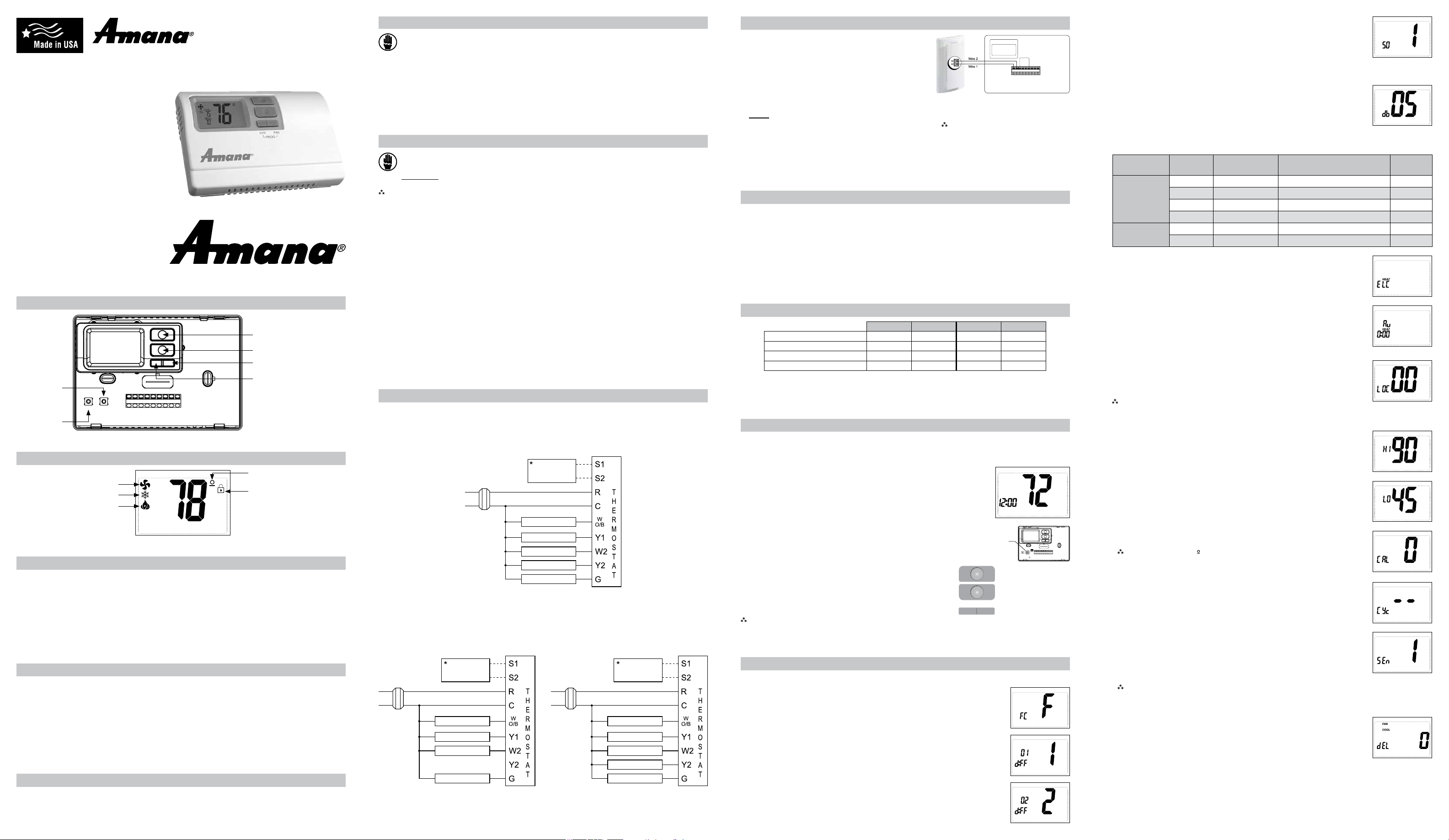
Terminals S1 and S2 can be used for an indoor remote sensor.
The indoor remote sensor is used to read the indoor temperature
in a different location. This is benecial when the thermostat is not
mounted in the ideal location.
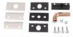
1. Remove cover from remote sensor housing.
2. Select an appropriate location for mounting the remote sensor.
3. Mount remote sensor unit using hardware provided.
4. Install two strand shielded wire between remote sensor and
thermostat. Shielded wire is recommended.
Do not run remote sensor wire in conduit with other wires.
• Wire 1 should run between the S1 terminal on the thermostat
and the S1 terminal on the remote sensor
• Wire 2 should run between the S2 terminal on the thermostat
and the S2 terminal on the remote sensor
• Connect the shielding of the wire to the S2 terminal on the thermostat
5. Congure the thermostat to operate with the remote indoor sensor (see Conguration Mode setting 13).
Remote Sensor Installation (Optional)
Note: Remoteoroutdoorsensorreadingcanbe
displayedbysimultaneouslypressingthe
DownandSYSbuttons.
Remote Sensor:
(Shown:OptionalICMACC-RT103RemoteIndoor
Sensor;foroutdoorsensor,orderACC-OD103.)
Specifications
Electrical rating: • 24 VAC (18-30 VAC)
• 1 amp maximum per terminal
• 3 amp maximum total load
Temperature control range: 45°F to 90°F (7°C to 32°C) Accuracy: ± 1°F (± 0.5°C)
System congurations: 2-stage heat, 2-stage cool, heat pump, gas, oil, electric
Timing: Anti-short Cycle: 4 minutes (bypass anti-short cycle delay by returning to OFF mode for 5 seconds)
Backlight Operation: 10 seconds
Terminations: S1, S2, R, C, W/O/B, Y1, W2, Y2, G
Package Contents/Tools Required
Package includes: Amana
®
2246008 thermostat on base, thermostat cover, wiring labels, screws and wall
anchors, Installation, Operation and Application Guide
Tools required for installation: Drill with 3/16” bit, hammer, screwdriver
Important Safety Information
WARNING!
:
Always turn off power at the main power supply before installing, cleaning, or removing
thermostat.
• This thermostat is for 24 VAC applications only; do not use on voltages over 30 VAC
• Do not short across terminals of gas valve or system control to test operation; this will damage your thermostat
and void your warranty
• All wiring must conform to local and national electrical and building codes
• Do not use air conditioning when the outdoor temperature is below 50 degrees; this can damage your A/C system
and cause personal injuries
• Use this thermostat only as described in this manual
To Remove Existing Thermostat
ELECTRICAL SHOCK HAZARD
– Turn off power at the main service panel by removing the fuse
or switching the appropriate circuit breaker to the OFF position before removing the existing
thermostat.
1. Turn off power to the heating and cooling system by removing the fuse or switching the appropriate circuit
breaker off.
2. Remove cover of old thermostat. This should expose the wires.
3. Label the existing wires with the enclosed wire labels before removing wires.
4. After labeling wires, remove wires from wire terminals.
5. Remove existing thermostat base from wall.
6. Refer to the following section for instructions on how to install this thermostat.
To Install Thermostat
ELECTRICAL SHOCK HAZARD
– Turn off power at the main service panel by removing the fuse
or switching the appropriate circuit breaker to the OFF position before removing the existing
thermostat.
IMPORTANT: Thermostatinstallationmustconformtolocalandnationalbuildingandelectricalcodesand
ordinances.
Note: Mountthethermostataboutvefeetabovetheoor.Donotmountthethermostatonanoutsidewall,in
directsunlight,behindadoor,orinanareaaffectedbyaventorduct.
1. Turn off power to the heating and cooling system by removing the fuse or switching the appropriate circuit breaker
off.
2. To remove cover, pull gently at the seam at the top.
3. Put thermostat base against the wall where you plan to mount it (Be sure wires will feed through the wire opening
in the base of the thermostat).
4. Mark the placement of the mounting holes.
5. Set thermostat base and cover away from working area.
6. Using a 3/16” drill bit, drill holes in the places you have marked for mounting.
7. Use a hammer to tap supplied anchors in mounting holes.
8. Align thermostat base with mounting holes and feed the control wires through slit in thermal intrusion barrier and
into wire opening.
9. Use supplied screws to mount thermostat base to wall.
10. Insert stripped, labeled wires in matching wire terminals.
CAUTION!
: Besureexposedportionofwiresdoesnottouchotherwires.
11. Gently tug wire to be sure of proper connection. Double check that each wire is connected to the proper
terminal.
12. Turn on power to the system at the main service panel.
13. Congure thermostat to match the type of system you have.
14. Replace cover on thermostat by snapping it in place.
15. Test thermostat operation as described in “Testing the Thermostat”.
Parts Diagram
Conguration
switch
Reset switch
Left (system) button
Right (fan) button
Down button
Up button
Icon Descriptions
Cooling operation icon
Fan operation icon
Heating operation icon
Lock mode activated
Room temperature
offset activated
S1 S2 R C W
O/B
GY1 W2 Y2
RESET CONFIG
Terminal Designator Descriptions
1
ST
Cool 2
ND
Cool 1
ST
Heat 2
ND
Heat
Heat/Cool Y1,G YI,Y2,G W1,G* W1,W2,G*
Heat Pump (One Compressor) Y1,G,O Y1,G,O Y1,G,B Y1,W2,G,B
Heat Pump (Two Compressors) Y1,G,O Y1,Y2,G,O Y1,G,B Y1,Y2,G,B
Electric Heat (Heat Pump Only) N/A N/A W2,G W2,G
* G not energized when congured as a gas/oil system
The Amana
®
2246008 thermostat is congurable for all systems. The conguration directly affects the outputs.
Use the output chart to correctly congure and wire the thermostat to your system.
Amana® 2246008 Output Chart
Configuration Mode
OFF
PM
1. Verify the Amana
®
2246008 is in the OFF mode.
Press the SYS (left) button until off mode displays.
2. Remove the cover of the thermostat by gently pulling near one of the corners at
the top of the thermostat.
3. Press the CONFIG button for 1 second while the Amana
®
2246008 is in OFF
mode.
To exit conguration mode, press the CONFIG switch for 1 second.
Press the up or down button to change settings within each screen.
Down button
Up button
Press the right button to advance to the next screen.
Note: Pressingthe
left
buttonwillreturnyoutothepreviousscreen.
Left
button
Right
button
The conguration mode is used to set the Amana
®
2246008 to match your heating/cooling system. The Amana
®
2246008 functions with heat pump, air conditioning, gas, oil or electric heat systems.
To congure the Amana
®
2246008, perform the following steps:
CONFIG
S1 S2 R C W
O/B
GY1 W2 W3Y2
RESET CONFIG
FP
R – 24 VAC hot
C – 24 VAC common
W1/O/B – Congurable
W1 – 1st stage heat for non-heat pump systems
O – cool active reversing valve
B – heat active reversing valve
Y1 – 1st stage cool, 1st stage heat for heat pumps
W2 – 2nd stage heat for non-heat pump systems, Electric Heat for heat pump systems
Y2 – 2nd stage cool for 2 compressor systems, 2nd stage heat for 2 compressor heat pump systems
G – Fan
Configuration Mode Settings
The setup screens for Conguration Mode are as follows:
1. Temperature Scale (F or C)
Choose Fahrenheit or Celsius.
Press the up or down button to select.
Press the
right
button to advance to the next screen.
2. 1
st
Stage Temperature Differential (1°F to 5°F) (0.5°C to 2.5°C)
Set the number of degrees between your “setpoint” temperature and your “turn on”
temperature.
Press the up or down button to set differential value.
Press the right button to advance to the next screen.
4. Staged Off Outputs
Select whether the outputs for heating and cooling are staged off independently or
are satised simultaneously.
1 = outputs staged off independently
0 = outputs off simultaneously
Press the up or down button to set.
Press the right button to advance to the next screen.
5. Minimum Deadband (1°F to 9°F) (1°C to 5°C)
Set the minimum separation between heat setpoint and cool setpoint in Auto
Changeover Mode.
Press the up or down button to set deadband value.
Press the right button to advance to the next screen.
7. Auxiliary Delay ON – (0-30 minutes) – Set the delay time in minutes for auxiliary heat
to be locked out after a call for second stage. This extra savings feature is used to
temporarily lock out auxiliary heat devices, allowing just heat pump to try to satisfy heat
call.
Press the up or down button to select.
Press the right button to advance to the next screen.
8. Lockout (0-8°, NITE, COOL-HEAT) – Select the number of degrees set temperature
can be changed during keypad lockout or select to lockout during NITE period only.
COOL-HEAT lockout allows adjustment of the set temperatures to the maximum heat
set temperature selected in Step 9 and minimum cool set temperature selected in
Step 10.
Note: Themodecannotbechangedwhenthethermostatislocked.
Press the up or down button to select.
Press the right button to advance to the next screen.
9. Maximum Heat Setpoint (45°F to 90°F) (7°C to 32°C)
Adjust to control the maximum heat set temperature allowed.
Press the up or down button to select.
Press the right button to advance to the next screen.
10. Minimum Cool Setpoint (45°F to 90°F) (7°C to 32°C)
Adjust to control the minimum cool set temperature allowed.
Press the up or down button to select.
Press the right button to advance to the next screen.
13. Temperature Sensor (1-4)
1. Only on-board sensor determines room temperature.
2. Only remote sensor determines room temperature.
3. Average temperature of on-board and remote sensor.
4. Only on-board sensor will be used until NITE period, and then only
remote sensor is used.
Note: Ifthereisnoremotesensor,option1mustbeselected.
Press the up or down button to select.
Press the right button to advance to the next screen.
12. Maximum Cycles Allowed Per Hour (- -, 2-6)
- - = as many as needed, 2-6 = maximum cycles/hour
Press the up or down button to select.
Press the right button to advance to the next screen.
11. Room Temperature Offset (+9°F to -9°F) (+4.5°C to -4.5°C)
Adjust to calibrate displayed room temperature to match actual room temperature.
Note: Whennotsetto0, willdisplay.
Press the up or down button to select.
Press the right button to advance to the next screen.
3. 2
nd
Stage Temperature Differential (1°F to 5°F) (0.5°C to 2.5°C)
Set the number of degrees between when stage 1 turns on and when stage 2 turns on.
Press the up or down button to set differential value.
Press the right button to advance to the next screen.
6. System – Set for heat pump, non-heat pump, reversing valve operation and number of compressors in your
system.
Press the up or down button to select.
Press the right button to advance to the next screen.
Choose System
Reversing Valve
Active
Number of Compressors
or Compressor Stages
Type of
Heat
Heat Pump
HP O 1
HP b 1
HP O 2
HP b 2
Non-Heat
Pump
Heat Gas
Heat Electric
OFF
14. Cooling Fan Delay Off Time (0, 30, 60, 90 seconds)
Select the fan purge time for cooling.
Press the up or down button to select.
Press the right button to advance to the next screen.
Wiring Diagrams
120
VAC
24 VAC
Heat #1
Cool #1
Heat #2
Cool #2
Fan
Transformer
Heat/Cool Systems
Optional
remote or
outdoor sensor
* outdoor sensor only reads outdoor temperature
120
VAC
24 VAC
Reversing Valve
Fan
Compressor
Auxiliary Heat #1
Single Compressor
heat pump with electric backup
Dual Compressor
heat pump with electric backup
120
VAC
24 VAC
Reversing Valve
Compressor #1
Electric Heat
Fan
Compressor #2
Transformer
Optional
remote or
outdoor sensor
Transformer
Optional
remote or
outdoor sensor
* outdoor sensor only reads outdoor temperature
• 7-Day, 5-2-Day or 5-1-1-Day Programmable
• Congurable
• 2-Stage Heat/2-Stage Cool Systems
• 2-Stage Heat Pump Systems
• Large Display With Backlight
• Selectable Fahrenheit or Celsius
• Compatible with Gas, Oil, or Electric
• Relay Outputs
(minimum voltage drop in thermostat)
• Remote Sensor Compatible
• Ideally Suited for:
– Residential (New Construction/Replacement)
– Light Commercial
Installation, Operation &
Application Guide
www.amana-ptac.com
2246008
Programmable Electronic Thermostat
2 Heat/2 Cool, Auto Changeover, Hardwire
Press the CONFIG button for 2 seconds to exit conguration.
Setting the Time and Day of the Week
TODAY MON
5. Press the FAN (right) button once to select day of the week (TODAY ashing).
Press the up or down button to select current day of the week.
Note: At any time, press the SYS (left) button to return to the previous screen or
press the FAN (right) button to advance to the next screen.
Press the PROG button in for 2 seconds to lock values into memory and return to the
OFF mode or press the FAN (right) button once to enter programming.
4. Press the FAN (right) button once to select minutes (minutes ashing).
Press the up or down button to adjust the minutes.
3. Time displays (hour ashing).
Press the up or down button to adjust the hour.
2. Press and hold the PROG button (SYS (left) and FAN (right) buttons pressed
simultaneously) in for 6 seconds.
1. Press the SYS (left) button until you are in the OFF mode.
The time and day of the week must be set for your program schedule to operate correctly.
Testing the Thermostat
Once the thermostat is congured, it should be thoroughly tested.
CAUTION!
:
Do not energize the air conditioning system when the outdoor temperature is below 50
degrees. It can result in equipment damage or personal injury.
Heat Test
1. Press SYS (left) button until heat mode is displayed.
2. Adjust the set temperature so it is 5 degrees above the room temperature.
3. Heat should come on within a few seconds.
4. Adjust the set temperature 2 degrees below the room temperature and the heat
should turn off. There may be a fan delay on your system.
Note:
For heat pumps, there is a four-minute delay to protect your compressor after it turns off. To bypass the
compressor time delay, go to OFF mode for 5 seconds.
PM
Cool Test
1. Press SYS (left) button until cool mode is displayed.
2. Adjust set temperature so it is 5 degrees below room temperature.
3. A/C should come on within a few seconds.
4. Adjust the set temperature 2 degrees above the room temperature and the A/C
should turn off. There may be a fan delay on your system.
Note:
There is a four-minute time delay to protect the compressor after it turns off. To bypass the compressor
time delay, go to OFF mode for 5 seconds.
PM
Fan Test
1. Press FAN (right) button. Fan displays. Indoor fan turns ON.
2. Press FAN (right) button. Indoor fan turns OFF.
PM
OFF
LIAF175
Mode of Operation
The Amana
®
2246008 is a programmable, manual or auto changeover, 2-stage heat, 2-stage cool thermostat. It
functions with air conditioning, heat pumps, gas, oil or electric heat systems. An outdoor sensor can be used to
monitor the outdoor temperature.
The thermostat activates the heating appliance when the room temperature is below the set heat temperature (by
the differential temperature). The Amana
®
2246008 will stop outputting when the call for heat has been satised.
With heat pumps, the thermostat will not let the compressor come on for 4 minutes after it turns off. This protects
your compressor.
When the room temperature is greater than the set cool temperature (by the differential temperature), the cooling
device is activated.. The Amana
®
2246008 will stop outputting when the call for cooling is satised. The thermostat
will not let the compressor come on for 4 minutes after it turns off. This protects your compressor.
The Amana
®
2246008 has ve possible operating modes: OFF, Heat, Cool, Heat & Cool, and Program mode. In
off mode, the thermostat will not turn on heating or cooling devices. The manual fan can be turned on in all operating
modes using the fan button. In heat mode, the thermostat controls the heating system. In the cool mode, the
thermostat controls the cooling system. In heat & cool mode, the thermostat controls both the heating and cooling
systems. In program mode, the thermostat will automatically be controlled by the set program. Program mode can
function with heat mode, cool mode, or heat & cool mode. The clock display alternates with the set temperature
display for heat & cool mode.
The program schedule can be overridden by changing the set temperature (up or down button). This puts the
Amana
®
2246008 thermostat into a 2-hour temporary hold. After 2 hours, it will automatically return to the program
schedule.
The programmable fan feature can be used to recirculate air while in Program mode. It is activated during the
program schedule set up.
The Amana
®
2246008 also has a button lockout feature. This enables the thermostat to be set to the proper mode
and temperature and locked so it cannot be tampered with.
Operating Modes
There are ve possible operating modes for the Amana
®
2246008. Off, Cool, Heat, and Cool & Heat modes are
accessed by pressing the SYS (left) button. Program mode is accessed by pressing the SYS (left) and FAN (right)
buttons simultaneously.
OFF Mode
• In this mode, the thermostat will not turn on the heating or cooling devices
Note: Theindoorfancanbeturnedonmanuallyineveryoperatingmodeby
pressingtheFAN(right)button.ThewordFAN showsonthedisplayand
thefanicon
appearswhenthefanoperates.
OFF
Heat Mode
• In this mode, the thermostat controls the heating system. When the heat outputs,
the ame icon
apprears on the display.
Note: Forheatpumps,thereisafourminutedelayforyourcompressorto
restartafterithasturnedoff.Tobypassthecompressortimedelay,goto
OFFmodefor5seconds.
Cool Mode
• In this mode, the thermostat controls the cooling system. When the cooling
outputs, the snowake icon
apprears on the display.
Note:Thereisafourminutedelayforyourcompressortorestartafterithas
turnedoff.Tobypassthecompressortimedelay,gotoOFFmodefor5
seconds.
Cool and Heat Mode (Auto Changeover)
• In this mode, the thermostat controls the cooling and heating systems, automatically
changing over from one to the other as needed.
• The timing display alternates with the set temperature every 10 seconds in the cool
and heat mode.
Electric Heat Mode (Heat pump systems only)
• In Electric Heat mode, the heat pump system will be disabled and auxiliary heat
will become the primary source of heat.
Button Functions
UP – Used to increase the time, set temperatures and to adjust conguration
settings.
DOWN – Used to decrease the time, set temperatures and to adjust
conguration settings.
SYS (left) – Used to change from OFF, HEAT, ELECTRIC HEAT, COOL
and AUTO changeover modes
FAN (right) – Used to turn on and off the indoor fan.
PROG (SYS and FAN) – Used to change from program operation to manual operation.
UP and PROG – Held in simultaneously for 10 seconds to lock and unlock the thermostat.
DOWN and SYS – Pressed simultaneously to display outdoor remote temperature if remote sensor is
connected.
PROG
FAN
(right)
Down
button
Up
button
SYStem
(left)
Programming
SUN MON TUE WED THU FRI SAT
PROG
From this screen you have 2 options:
1. Press the FAN (right) button to begin programming all 7 days at one time, or
2. Press the
up
button to see the other programming options.
Note: The days of the week shown on the display will be programmed simultaneously.
The screens are listed below.
Screen 1 SUN MON TUE WED THU FRI SAT
Screen 2 MON TUE WED THU FRI
Screen 3 MON
Screen 4 TUE
Screen 5 WED
Screen 6 THU
Screen 7 FRI
Screen 8 SUN SAT
Screen 9 SAT
Screen 10 SUN
Program Overview
The Amana
®
2246008 programmable thermostat has four periods (MORN, DAY, EVE, NITE) that are customizable
for each day of the week. Each period will have a start time, heat temperature, cool temperature and programmable
fan option. The Amana
®
2246008 monitors the day and time, while maintaining the specic conditions you have
chosen for each period in your program.
Setting the program schedule:
1. Press the SYS (left) button until you are in OFF mode.
2. Press and hold the PROG button (SYS and FAN buttons pressed simultaneously) for 6 seconds.
3. Press the FAN (right) button 3 times.
4. SUN thru SAT are blinking.
Lockout Feature
The Amana
®
2246008 has a button lockout feature so the mode cannot be changed
and the temperature adjustment is limited. Select the appropriate lockout from
Conguration Mode Settings (Step 8) of this guide.
To activate the LOCK feature:
1. Simultaneously press the SYS, FAN and UP buttons for 10 seconds.
2.
will display and the lockout function will be enabled.
To deactivate the LOCK feature, repeat steps 1 and 2 above.
From any of the screens on above, you can press the FAN (right) button to begin entering your program schedule.
The days shown on the display will all be programmed simultaneously.
Once the FAN (right) button is pressed, MORN blinks.
Use the up or down button to select a different period (MORN, DAY, EVE, NITE).
Press FAN (right) button to advance to the next screen. Transition time hour blinks.
Use the up or down button to select a different hour.
Press FAN (right) button to advance to the next screen. Transition time minutes blink.
Use the up or down button to select different minutes.
Press FAN (right) button to advance to the next screen. Heat set temperature displays.
Use the up or down button to adjust the heat set temperature.
Press FAN (right) button to advance to the next screen. Cool set temperature displays.
Use the up or down button to adjust the cool set temperature.
Press FAN (right) button to advance to the next screen. Programmable fan screen displays.
Use the up or down button to select:
Choose: Off – Programmable fan disabled >OR< On – Indoor fan on continuously
Note: Programmable fan operates in Program mode only.
Repeat above steps to program the four periods per day.
When the program schedule is complete, press and hold the PROG button (SYS and FAN buttons pressed
simultaneously) in for 2 seconds to return to the OFF mode.
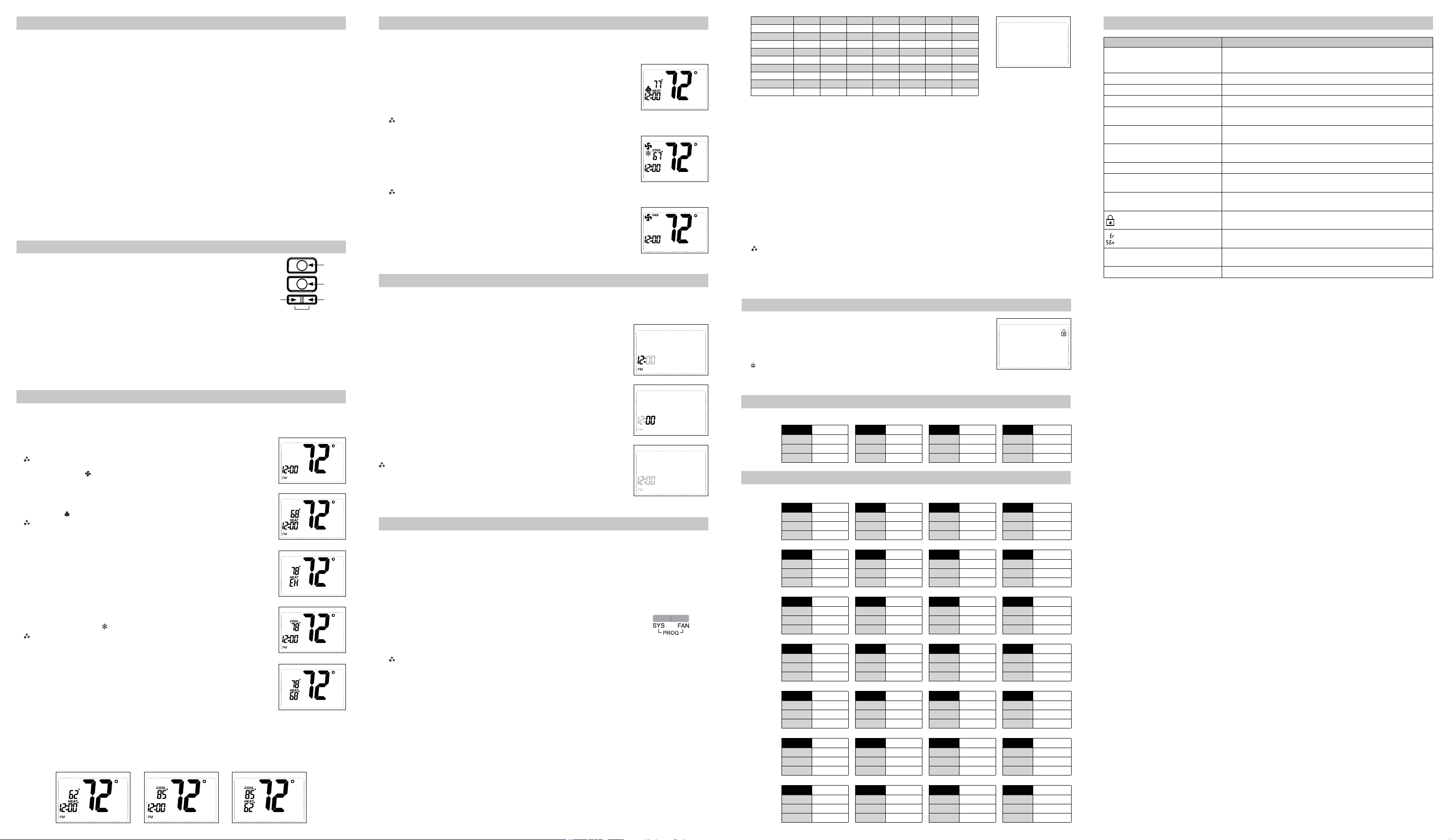
Symptom Remedy
No display Check for 24 VAC at thermostat; display is blank when 24 VAC is not
present
Time and day of week must be reset after extended power loss
System fan does not come on properly Verify wiring is correct, check Gas/Electric Conguration (see Setting 6)
All thermostat buttons are inoperative Verify 24 VAC is present; unit locks out when 24 VAC is not present
No response with rst button press First button press activates backlight only
Program schedule activates at the
wrong time
Check time (AM/PM) set on thermostat (see Setting the Time)
Thermostat turns on and off too
frequently
Adjust temperature differential (see Conguration Mode Settings 2 & 3)
Thermostat does not follow program Verify it is operating in program mode (PROG displays); check time
(AM/PM); check if in 2 hour program override
Fan runs continuously Press FAN (right) button to turn fan off
Fan turns on occasionally Program Mode: Check programmable
fan setting in program schedule
Room temperature is not correct Calibrate thermostat (see Conguration Mode Setting 11)
If remote sensor is used, check S1 and S2 terminal connections
displays when any button is
pressed
Thermostat has the button lockout function activated
(see Lockout Feature and Conguration Mode Setting 8)
on display instead of room
temperature
Check for a bad connection at S1 and S2 terminals, if used
(see Conguration Mode Setting 13)
Heat or Cool not coming on Verify wiring is correct, gently pull on each wire to verify there is a good
connection at terminal block
Problem not listed above Press Reset button once*
* Reset Button Function:
Time and day are reset, conguration and program settings are unchanged.
Troubleshooting
THURSDAY
4
MORN DAY EVE NITE
HEAT HEAT HEAT HEAT
COOL COOL COOL COOL
FAN FAN FAN FAN
FRIDAY
5
MORN DAY EVE NITE
HEAT HEAT HEAT HEAT
COOL COOL COOL COOL
FAN FAN FAN FAN
SATURDAY
6
MORN DAY EVE NITE
HEAT HEAT HEAT HEAT
COOL COOL COOL COOL
FAN FAN FAN FAN
SUNDAY
7
MORN DAY EVE NITE
HEAT HEAT HEAT HEAT
COOL COOL COOL COOL
FAN FAN FAN FAN
Factory Preprogramming
MORN 6:00 AM DAY 8:00 AM EVE 6:00 PM NITE 10:00 PM
HEAT 70°F HEAT 62°F HEAT 70°F HEAT 62°F
COOL 78°F COOL 85°F COOL 78°F COOL 82°F
FAN Off FAN Off FAN Off FAN Off
MONDAY
thru
SUNDAY
Personal Program Schedule
MORN DAY EVE NITE
HEAT HEAT HEAT HEAT
COOL COOL COOL COOL
FAN FAN FAN FAN
MONDAY
1
TUESDAY
2
MORN DAY EVE NITE
HEAT HEAT HEAT HEAT
COOL COOL COOL COOL
FAN FAN FAN FAN
WEDNESDAY
3
MORN DAY EVE NITE
HEAT HEAT HEAT HEAT
COOL COOL COOL COOL
FAN FAN FAN FAN
The Amana
®
2246008 comes preprogrammed with the following schedule:
Use the following personal program schedule to record your settings:
Program Mode
• In this mode, the program function is on (PROG displays), and the thermostat will automatically be controlled by
the set program schedule. Program mode can function with heat mode, cool mode, or heat & cool mode. The
program schedule can be overridden by changing the set temperature (up or down button). After 2 hours, the
program schedule will automatically be resumed. To manually return to the program schedule, press the PROG
button twice.
PROG PROGPROG