Loading ...
Loading ...
Loading ...
page 7
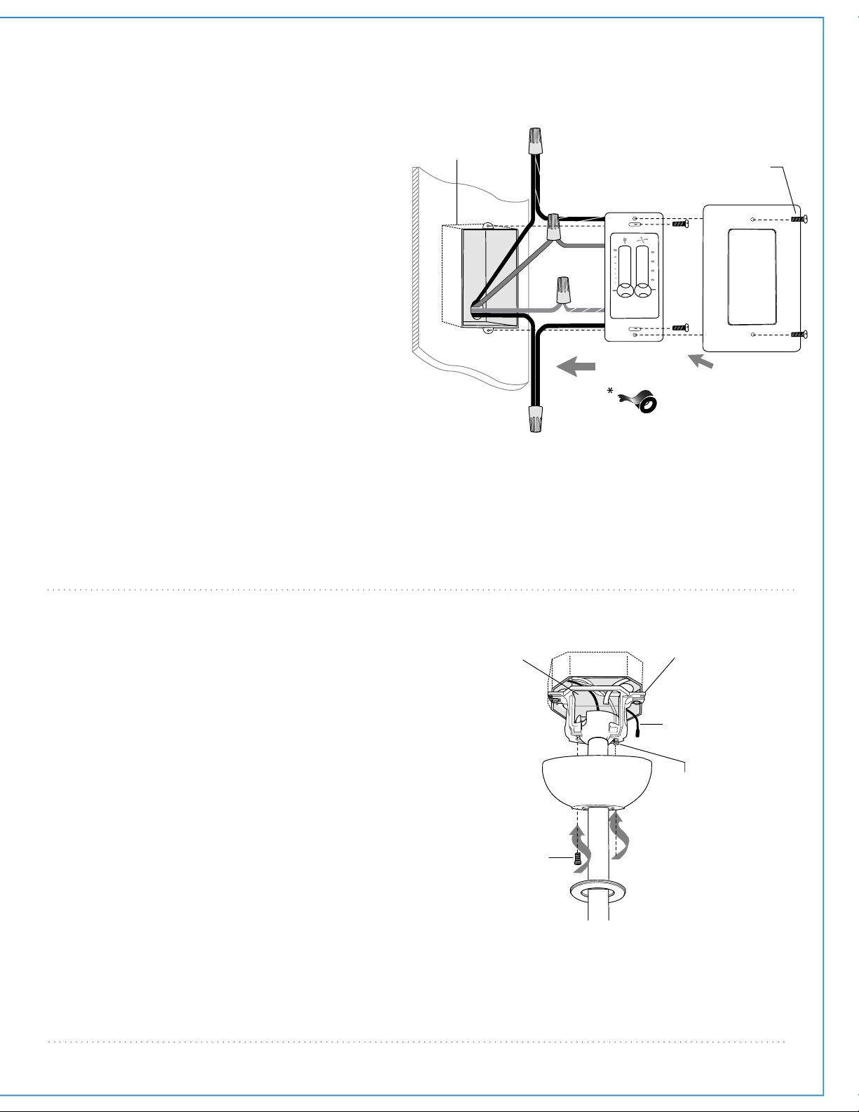
8. Canopy Assembly.
Locate 2 screws on underside of hanging
bracket and remove screw closest to the open
end of the hanging bracket. Partially loosen
the other screw. Lift canopy to hanging
bracket. Place rounded part of slotted hole in
canopy over loosened screw in hanging
bracket and push up. Twist canopy to lock.
Re-insert screw that was removed and then
tighten both screws securely.
Slide canopy cover up to canopy, aligning
rounded part of slotted holes in canopy cover
with screwheads in bottom of canopy. Turn
canopy cover to the right (clockwise) until it
stops.
hanging
bracket
antenna
canopy
screw
screw
receiver
canopy cover
7. Wiring - Wall Control
Remove existing wall switch. Wire the wall
control as shown in diagram at right.
Connect BLACK/WHITE wire from wall
control to BLACK (AC IN L) wire in outlet box.
Connect BLACK wire from wall control to
BLACK (AC IN N) wire from fan (inside the
outlet box). Connect BLUE wire from wall
control to BLUE wire from light in the outlet
box. Connect GREEN/YELLOW ground wire
from wall control to ground wire in the outlet
box. Use wire connectors provided when
making connections.
*Wrap each wire connector separately with
electrical tape as an extra safety measure.
Gently push wires and taped wire connectors
into outlet box.
Attach wall control to outlet box and secure
with screws from original wall switch. Attach
plate (included) to wall control using 2 screws
provided with the wall control.
plate
wall control
plate
screw
outlet box
BLACK
(AC IN N
from fan)
BLACK
BLUE
GREEN/
YELLOW
BLACK
(AC IN L)
BLACK/WHITE
green/
bare
ground
BLUE
(wiring for wall control)
Loading ...
Loading ...
Loading ...