Loading ...

Oilless Compressors
General Safety (Con't)
5. Wear sefetyglasses
andusehearing
protection when
operating the pump
or uniL
6. Do not stand on or
use the pump or unit as a handhold.
7. Before each use. inspect compressed
air system and electrical components
for signs of damage, deterioration.
weakness or leakage. Repair or
replace defective items before using.
8. Check all fasteners at frequent
intervals for proper tightness.
MotorJ, electb_l
equipment and €_trols
can (•us* elettrlcal arcs
that will Ignite •
flammable gas or vapor.
Neverv_roperateteor rtpmlr in or near a
flarnmable gas or vapor. Never store
flanm_ble Uqulds or gases In the
_fdnfly of the mmpressor.
9. Keep fingers away
from a running
compressor, fast moving and hot
parts will cause injury and/or burns
10. If the equipment should start to
abnormally vibrate. STOP the
eng_ioe/motor and check
immediately for the cause.
Vibration is generally a warning of
trouble.
11. To reduce fire hazard, keep
engine/motor exterior free of oil,
solvent, or excessive grease.
Nel/_r ilmovii or
_-W-ARNtNG7 °t_m.t tond/._r
s•_fy valvt. Keep safety valve free
from paint and other _mulatlons.
13. Fast moving air will stir up dust and
debris which may be harmful.
Release air slowly when draining
moisture or depressurizing the
compressor system.
SPRAYING PRECAUTIONS
IAWARNINGi
Do not s_'•y flammabM
mterinl• In vkinlty of
_l_m flm or r_
Iswltlon sources
ItmkKting the €ompre_ u_lt
14. DO not smoke when s;prrayingpaint.
insecticides, or other flammable
substances.
15. Use a face mask/ r _ I
respirator when
spraying and spray in
a well ventilated area
to prevent health and
fire hazards,
16. DO not direct paint or other sprayed
material at the compressor. Locate
compressor as far away from the
swaying area as possible to
minimize overspray accumulation
on the compressor.
17. When spraying or cleaning with
solvents or toxic chemicals, follow
the instructions provided by the
chemical manufacturer.
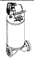
Foot Assembly
The items marked with an asterisk (*)
were shipped loose with the unit (See
Figure 1).
1. Insertboltthroughfootand
bracket. The foot should be on the
lower side of bracket.
2. Tightly secure with the lock nut.
Repeat on opposite side.
Wheel Assembly
The items markedwith an asterisk(*)
were shipped loose with the unit See
I_r attempt 1Orel_lr Figure 1).
ormodlfyat_kl t. losers shoulder bolt through wheel
Welding. drllgng or any hub. The bolt hex head should be
oth_ modlfl_tl_ will on the opposite side of protruding
weaken the trunk
resulting In damage from rupture or hub center.
explos/cm. A/ways/_pMce worn or
d_nag_l tank_
Drain I Id from
12 Tanks rust from moisture build-up_
which weakens the tank_ Make sure
to dra_n tank da_y and inspect
periodically for unsafe conditions
such as rust formatidn and
corrosion_
2. OnWL6tl2Only: Place washers
onto shoulder bolt so that washers
are between wheel and tank axle
iron.
3. Feed th_ shoulder bolt through the
hole on the tank axle iron and
tightly secure with the iocknut.
Repeat on the opposite side.
Nut*
Bolt* Shoulder
Bolt* Wheel*
Figure 1 - Foot and Wheel Assembly
Installation
LOCATION
The tank must sit level or slope slightly
towards the drain cock to allow the
tank to drain properly.
it isextremely important to install the
compressor in a clean, well ventilated
area where the surrounding air
temperature will not be more than
100°F.
A minimum clearance of 4 inches
between the compressor and a wall is
required because object_ could obstruct
air flow.
Do not lo_•te the
Inlet near _ear_ pilot spray, sandblast
I_0•$ or •ny other SOU_I! o_
_•mlnatio_ This debris will d,_ma_
ELECTRICAL INSTALLATION
All wirln and
ele_rlcaY
connections should be performed by I
qulllNnd electrician. Installation must
be in accordance with Ioc•l codes and
nlticnll e/ectrkil (ode_
Nay•ruse _n extension
cord with this product.
Use additional lit hose
Instead of in eXlhmslon
cord to •_old power loss
•nd permanent motor dam•g•. Use of
an exlon$lon cord voids the warranty.
GROUNDING INSTRUCTIONS
1. This product Is for use on a nominal
120 volt circuit and has a grounding
plug that looks like the plug
illustrated in Figure 2. Make sure the
product isconnected to an outlet
having the same configuration as the
plug. This product must be
grounded, tn the event of an
electrical short circuit, grounding
reduces risk of electrical shock by
providing an escape wire for electric
current. This product is equipped
with a cord having a grounding wire
www.thl=ew_.o=_n
2
Loading ...
Loading ...
Loading ...