Loading ...
Loading ...
Loading ...
12
Connect Power
2
• DO NOT use ANY power supply other
than those supplied with your CAPXS.
• DO NOT power electronic strikes and
latches with the same power supply
used to power the access control panel;
doing so will cause DAMAGE to the
CAPXS. Use ONLY a UL listed burglar
alarm or access control system to
power electronic strikes and latches.
• DO NOT connect the power supply to a
switched outlet or otherwise controlled
AC outlet.
• DO NOT connect the power supply to
the 120 Vac outlet until ALL wiring is
completed.
• DISCONNECT the power supply from
the 120 Vac outlet prior to inserting or
removing wires from the terminal block
to the Control Board.
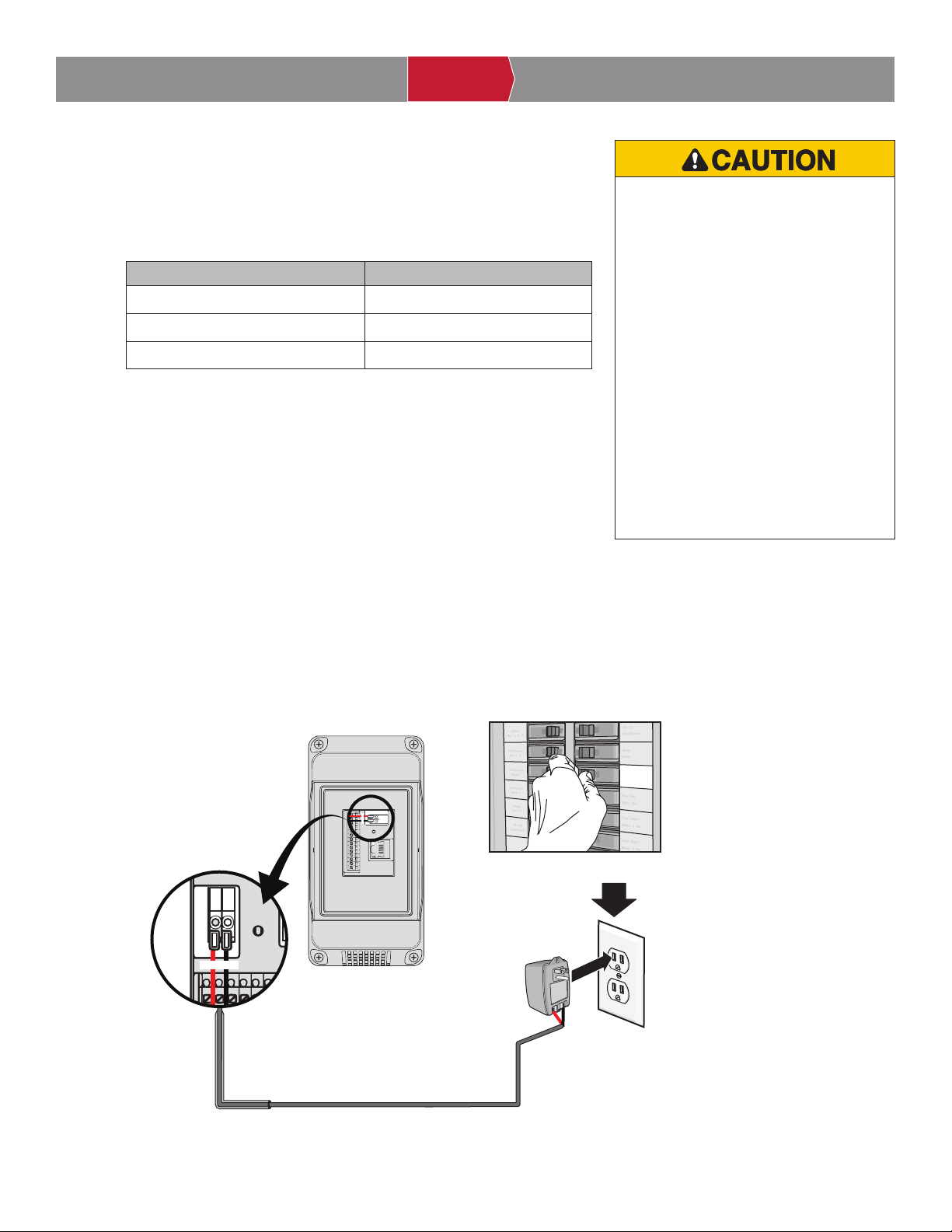
The outlet for the CAPXS MUST be an external dedicated 120 Vac outlet.
Refer to the table below for maximum wire run distances. This outlet should
be wired back to its own 10 Amp minimum circuit breaker.
1. Connect 14-18 AWG wire to the screw terminals on the power supply.
Use 2 conductor, Red/Black, jacketed wire. Use Red for + and Black
for -.
2. While pushing down the orange tab on the CAPXS power input
connector on the Control Board, insert the stripped wire into the
respective polarity input.
3. Release the orange tab on the power input connector to lock the wire in
place.
4. Plug the power supply into a 120 Vac outlet after all connections have
been made.
NOTE: Green LEDs on the Control Board will light when powered
up. The CAPXS will display a MyQ logo while booting up. When
boot up is complete, the user interface will appear.
ACCOUNT SETUP NETWORK/MOUNTINGPOWER ACCESS CONTROLINTRODUCTION
INTRODUCTION ACCOUNT SETUP NETWORK/MOUNTINGPOWER ACCESS CONTROL
INTRODUCTION ACCOUNT SETUP NETWORK/MOUNTINGPOWER ACCESS CONTROL
INTRODUCTION ACCOUNT SETUP NETWORK/MOUNTINGPOWER ACCESS CONTROL
INTRODUCTION ACCOUNT SETUP NETWORK/MOUNTINGPOWER ACCESS CONTROL
Dedicated 10 Amp Minimum Circuit
120 Vac
Dedicated Outlet
Power Supply
NOTE: If the power supply is installed outdoors, the
power supply must have its own approved NEMA 4
Rated weatherproof electrical enclosure. Use conduit
from the power supply enclosure to the controller
enclosure.
When the power supply (low voltage) wiring leaves the
enclosure, the wire must be rated for wet and damp
locations.
High voltage wiring must be run in a separate conduit
from low voltage wiring.
+ 16 VDC –
+ 16 VDC –
WIRE SPECIFICATION MAXIMUM RUN DISTANCE
14 AWG Up to 300 feet (91.4 m)
16 AWG Up to 200 feet (60.9 m)
18 AWG Up to 100 feet (30.4 m)
Loading ...
Loading ...
Loading ...