Loading ...
Loading ...
Loading ...
7
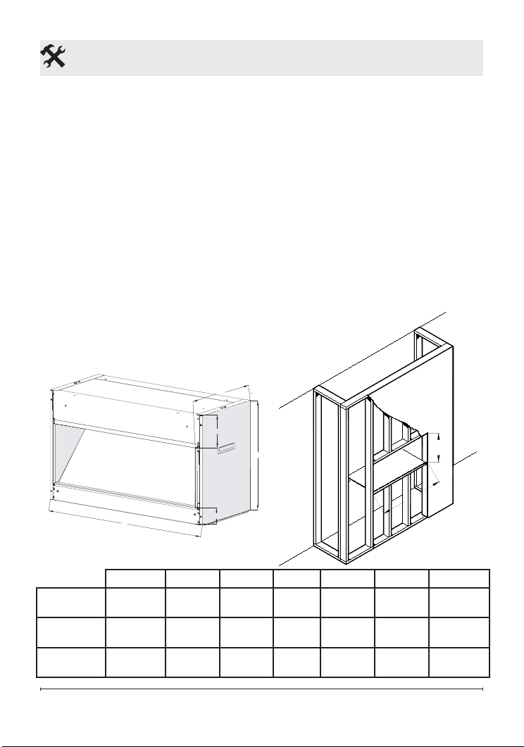
Opti-V Installation
recommended dimensions
located in Figure 1.
!
NOTE: Dimensions provided
are minimum clearances and will
vary depending on type of support
framing and nishing options.
!
NOTE: Framing should be
constructed to support:
VF2927L / VFA2927 - 63 lbs (29 kg)
VF5452L - 116 lbs (52 kg)
2. Allow up to 4 ft. (121.9 cm) of
service cable for connecting
a power supply wire to the
cable clamp on the Opti-V
when installing before nish-
ing wall.
!
NOTE: A 15 amp, 120 volt
alternating current (VAC) circuit
is recommended, but the unit is
constructed that it can operate
using voltages from 120-240VAC.
!
NOTE: Use minimum 14 AWG
supply cable with two insulated
copper conductors (white and
black) and one bare ground wire.
C
B
A
E
D
A B C D E F G
VF5452L
53.4 in
(1356 mm)
17.7 in
(450 mm)
13.6 in
(345 mm)
2.9 in
(74 mm)
5.3 in
(135 mm)
18.6 in
(474 mm)
55.3 in
(1404 mm)
VF2927L
29.0 in
(736 mm)
17.7 in
(450 mm)
13.6 in
(345 mm)
2.9 in
(74 mm)
5.3 in
(135 mm)
18.6 in
(474 mm)
29.9 in
(760 mm)
VFA2927
29.0 in
(736 mm)
17.7 in
(450 mm)
13.6 in
(345 mm)
2.9 in
(74 mm)
5.3 in
(135 mm)
18.6 in
(474 mm)
29.9 in
(760 mm)
Figure 1
G
F
Loading ...
Loading ...
Loading ...