Loading ...
Loading ...
Loading ...
3. TOOLS REQUIRED
1. 1/2" or Adjustable Wrenches
2. 7/16" or Adjustable Wrenches
3. Funnel
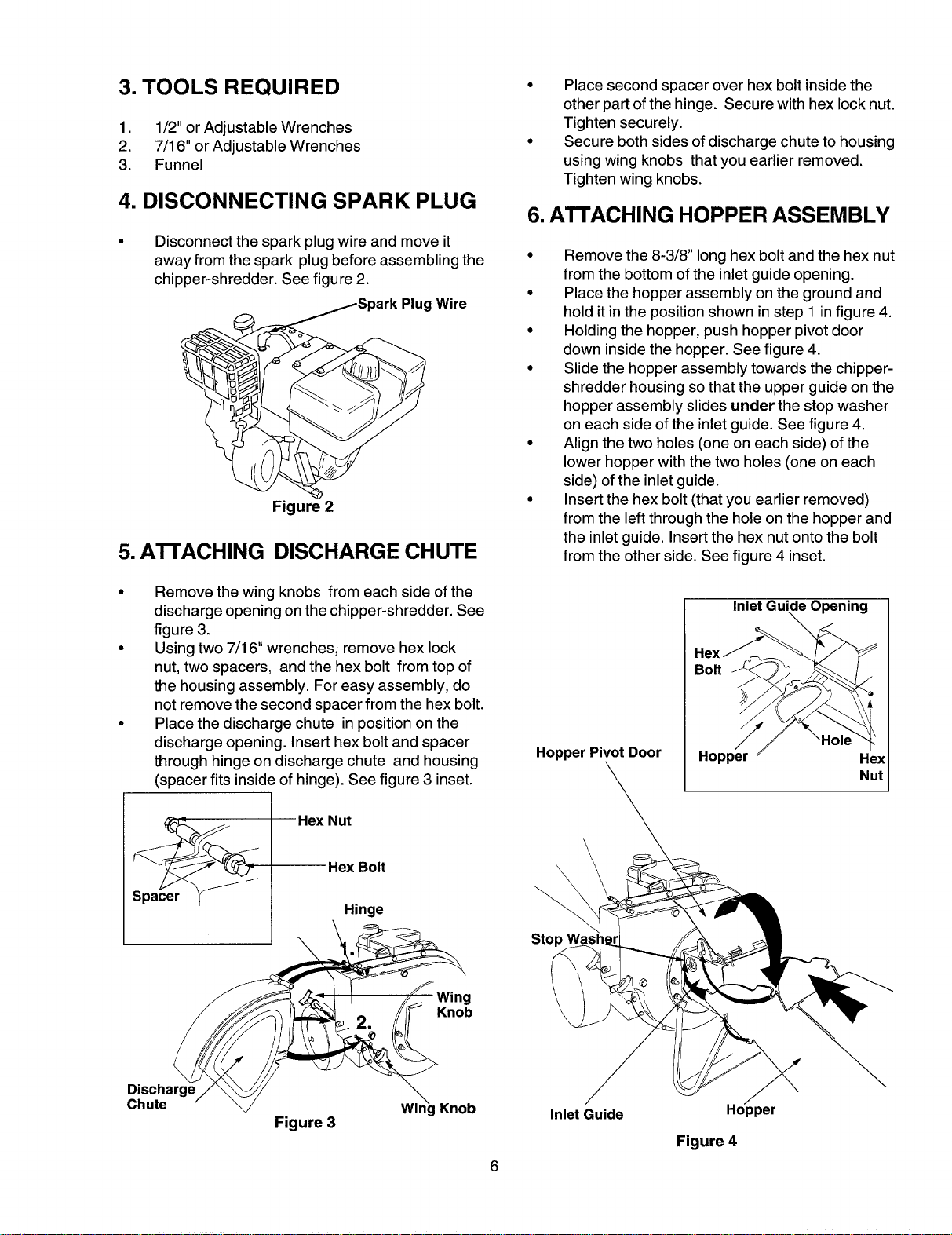
4. DISCONNECTING SPARK PLUG
Disconnect the spark plug wire and move it
away from the spark plug before assembling the
chipper-shredder. See figure 2.
r_ /Spark PlugWire
Figure 2
5. A'I-rACHING DISCHARGE CHUTE
Remove the wing knobs from each side of the
discharge opening on the chipper-shredder. See
figure 3.
Using two 7/16" wrenches, remove hex lock
nut, two spacers, and the hex bolt from top of
the housing assembly. For easy assembly, do
not remove the second spacer from the hex bolt.
Place the discharge chute in position on the
discharge opening. Insert hex bolt and spacer
through hinge on discharge chute and housing
(spacer fits inside of hinge). See figure 3 inset.
Place second spacer over hex bolt inside the
other part of the hinge. Secure with hex lock nut.
Tighten securely.
Secure both sides of discharge chute to housing
using wing knobs that you earlier removed.
Tighten wing knobs.
6. A'n'ACHING HOPPER ASSEMBLY
Remove the 8-3/8" long hex bolt and the hex nut
from the bottom of the inlet guide opening.
Place the hopper assembly on the ground and
hold it in the position shown in step 1 in figure 4.
Holding the hopper, push hopper pivot door
down inside the hopper. See figure 4.
Slide the hopper assembly towards the chipper-
shredder housing so that the upper guide on the
hopper assembly slides under the stop washer
on each side of the inlet guide. See figure 4.
Align the two holes (one on each side) of the
lower hopper with the two holes (one on each
side) of the inlet guide.
Insert the hex bolt (that you earlier removed)
from the left through the hole on the hopper and
the inlet guide. Insert the hex nut onto the bolt
from the other side. See figure 4 inset.
Hopper Pivot Door
Inlet Guide Opening
Hopper Hex
Nut
J
J
Hex Nut
Hex Bolt
Hinge
Stop
\
Knob
Discharge
Chute
Figure 3
Knob
6
Inlet Guide
Hopper
Figure 4
Loading ...
Loading ...
Loading ...