Loading ...
Loading ...
Loading ...
13
OPERATION
2
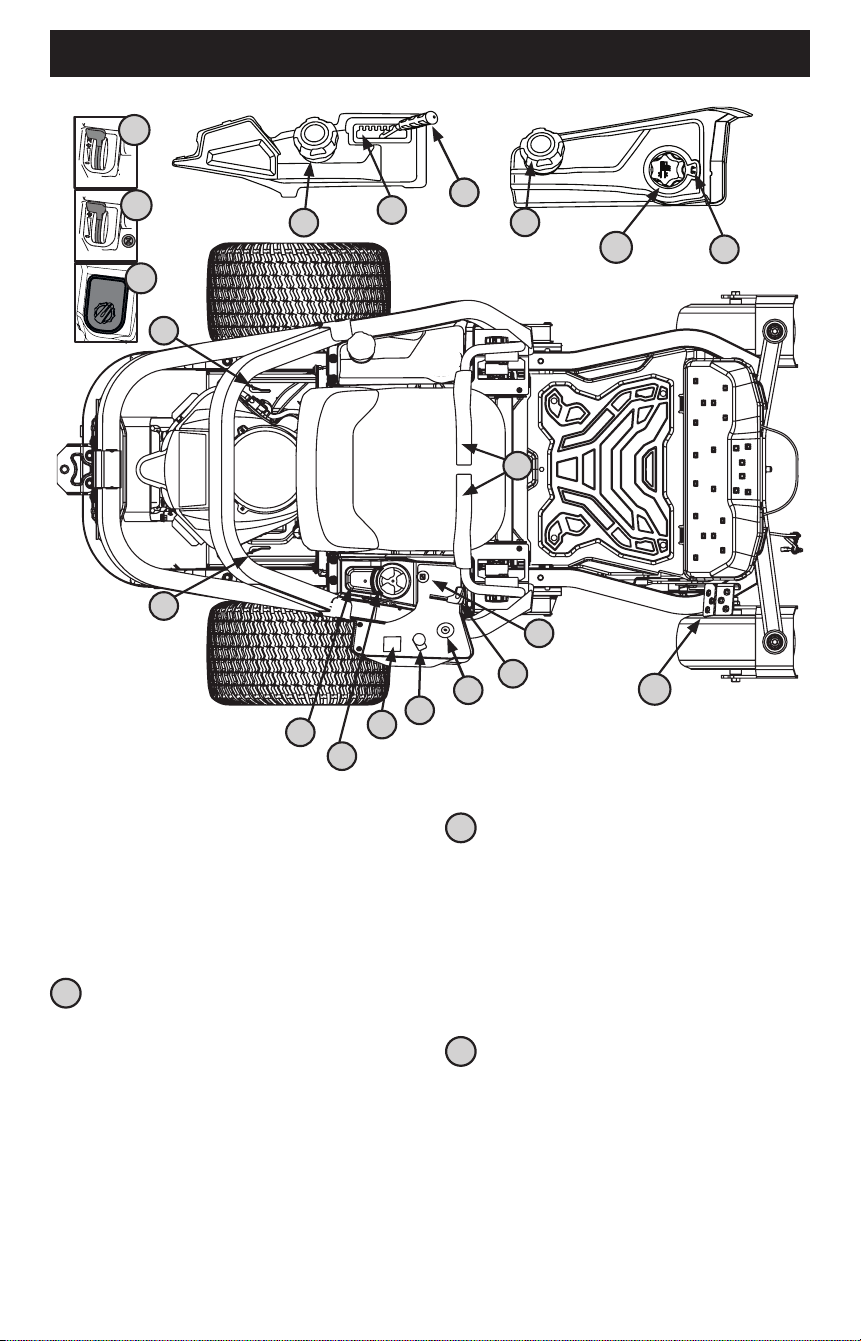
Deck Height Index
If equipped with a deck lift handle:
Each height index notch corresponds to approximately a 1⁄2”
(12.7 mm) change in deck height. See 3 in Figure 17.
If equipped with a deck lift pedal and knob:
Each rotation represents a 1⁄4” (6.35 mm) change in deck height.
Positions range from 1” (2.5 cm) to 4-1/2” (11.4 cm) at the
highest point. See 4a and 4b in Figure 17.
3
Deck Lift Handle (If Equipped)
The deck lift handle is used to raise and lower the mower deck.
To lower the deck, pull the deck lift handle to the right out of the
index notch and push downward. To raise the deck, pull upward.
Ensure handle is fully positioned into the height index notch
when the desired height is attained.
NOTE: This Operator’s Manual covers several models. Tractor
features may vary by model. Not all features in this manual are
applicable to all tractor models and the tractor depicted may
differ from yours.
NOTE: All references in this manual to the left or right side and
front or back of the tractor are from the operating position only.
Exceptions, if any, will be specified.
1
Lapbar Drive Control Levers
The RH (Right Hand) and LH (Left Hand) lapbar drive control levers
are located on each side of the operator’s seat. The hinged levers
pivot outward to permit the operator to sit in the seat or dismount.
To start the tractor’s engine, the lapbar drive control levers must
be fully out and in park position. When the lapbar drive control
levers are fully outward, the parking brake is engaged.
Each drive control lever controls the respective transmission.
Consequently, these levers control all of the tractor’s movements.
Driving and steering using these control levers is quite different
from a conventional tractor and will take practice to master.
Refer to Practice Operation section for further instructions.
1
2
3
4a
5
6
8
9
10
11
12
13
10
2
4b
12a
12b
12c
7
7
Figure 17
Loading ...
Loading ...
Loading ...