Loading ...
Loading ...
Loading ...
USING HOLD DOWN/PUSH BLOCKS
Refer to Figure 15
• Always use hold-down/push-blocks when jointing, or
rabbeting wood that is narrower than 3", planing
wood thinner than 3"
Figure 15 - Feeding with Push Blocks
• Grasp the hold-down/push-blocks firmly
• Position the push-blocks flat on top of workpiece and
push the workpiece down against the table
• Use a hand-over-hand motion to maintain control
over the workpiece at all times
• When planing workpiece between 1__3/4.and nar-
rower than the push-blocks, tilt the push-blocks so
that it clears the cutterhead guard while feeding
BEVELING AND CHAMFERING
Refer to Figure 16.
• The fence on the jointer/planer is adjustable to 45 °
outward Adjust the fence to the desired angle and
tighten fence lock knobs
• Beveling refers to cutting the entire edge of a board
at an angle Beveling may require several passes
due to the depth of cut needed
• Chamfering refers to removing only the corner of the
edge of a board Normally a chamfer is made on one
pass; so a _/_6"depth of cut is made
Bevel Edge
WARNING: Turn the switch to "Off" position and
unplug jointer/planer from power source before pro-
ceeding to do maintenance work.
CHECKING FOR WORN BLADES
Condition of blades willaffect precision of cut. If blade
wear is not observed when checking the blade height,
the quality of cut will indicate the blade condition Dull
blades will tear rather than sever wood fiber A raised
grain will occur when dull blades pound on wood where
there is difference in density A raised ridge will be pro-
duced where the blades have been nicked
SHARPENING BLADES
The blades can be honed individually by whetting them
with a fine sharpening stone Make sure oilstone is flat
and is not worn To sharpen blades:
• Partially cover the stone with paper to protect the
table top
• Position infeed table so stone will contact blade
along its beveled surface
• Stroke the stone across blade from one side to other
while stone is also moved slightly in the direction of
feed
• Make sure to do the same number of strokes on
each blade
If the blades are nicked they must be replaced
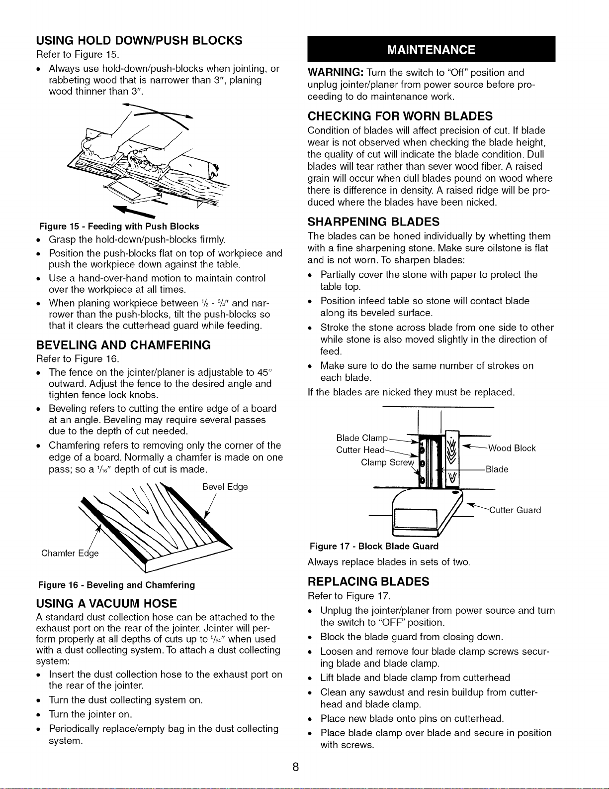
Blade Clam
Cutter
Clamp
Guard
Chamfer Edge
Figure 16 - Beveling and Chamfering
USING A VACUUM HOSE
A standard dust collection hose can be attached to the
exhaust port on the rear of the jointer Jointer will per-
form properly at all depths of cuts up to %/' when used
with a dust collecting system To attach a dust collecting
system:
• Insert the dust collection hose to the exhaust port on
the rear of the jointer
• Turn the dust collecting system on
• Turn the jointer on
• Periodically replace/empty bag in the dust collecting
system
Figure 17 - Block Blade Guard
Always replace blades in sets of two.
REPLACING BLADES
Refer to Figure 17.
• Unplug the jointer/planer from power source and turn
the switch to "OFF" position
• Block the blade guard from closing down
• Loosen and remove four blade clamp screws secur-
ing blade and blade clamp
• Lift blade and blade clamp from cutterhead
• Clean any sawdust and resin buildup from cutter-
head and blade clamp
• Place new blade onto pins on cutterhead
• Place blade clamp over blade and secure in position
with screws
8
Loading ...
Loading ...
Loading ...