
Operator's manual (CARB II, EPA II) /r /_
326 H S75 x-,e,-ie,
326HS99x.,erie,
Please read these instructions carefully and make
sure you understand them before using the machine. English

SYMBOL EXPLANATION
Symbols
WARNING! The hedge trimmer can be
dangerous!
Careless or incorrect use can result in
serious, even fatal injury.
Read through tile Operator's Manual
carefully and understand the content
before using the hedge trimmer.
Always use
• Ear protection
• Approved eye protection
• This product is in accordance with
applicable CE directives.
• Always wear approved protective
gloves.
Other symbols/decals on the machine refer to
special certification requirements for certain
markets.
Checks and/or maintenance should be
carried out with the engine switched off,
with the stop switch in the STOP position.
Awyueroeroeveove
I_ I Regular cleaning required.
I_ I Ocular control.
Approved eye protection must always be
used.
2 - English

CONTENTS
Husqvarna AB has a policy of contirmous product
development and therefore reserves the right to modify the
design and appearance of products without prior notice.
Maintenance, replacement, or repair of the emission control
devices and systems may be performed by any nonroad
engine repair establishment or individual.
i!!iiii!:ilill ¸!,iiiii i iiii!iill¸!ii!ili¸ii¸ii ili¸ii i i i!i!i!i! !ili¸I¸ili ii :!¸iii!i!i ii !i !iiii !iiiii i! ii i !i;¸!!iii!ii!i:iiii! !i!ii iiii iii i!!i! i!:iiii! !ii ii IJi!i¸i ii i !!i ¸ili!i i !ili i!ii :iiii!i !
IMPORTANT ENGINE INFORMATION
HUSQVARNA AB HDSXVARNASWEDEN TWC
CALIFORNIAEMISSON REGULAItONSFOR SMALL OFF*
ROADENGINES,REFERTOOPERATOR"S MANUALFOR
MAINTENANCESPECIFICATIONSANDADJUSTMENTS,
THEAIR INDEX OFTHIS ENGINEIS 3
ri_l 41 i 61 i 81 I 101
THE LOWERTHEAIR INDEX,THE LESSPOLLUTION
EMISSIONSCOMPLIANCE PERIOD:CATEGORY
This decal certifies that the product has beer] approved in
accordance with American exhaust emissions requirements
EPA Ph II and CARB Tier II.
The Emissions Compliance Period referred to on the
Emissions Compliance label indicates the rmmber of operating
hours for which the engine has been shown to meet Federal
arm California emission requirements.
Category C = 50 hours, B = 125 hours, and A = 300 hours.
WARNING
The engine exhaust from this product
contains chemicals known to the State
of California to cause cancer, birth
defects or other reproductive harm.
List of contents
SYMBOL EXPLANATION
Symbols ............................................................................... 2
CONTENTS
List of contents .................................................................... 3
SAFETY INSTRUCTIONS
Personal protective equipment ............................................. 4
The machine's protective equipment .................................... 4
Control, maintenance and service of the hedge trimmer's
protective equipment ..................................................... 6
General safety instructions ................................................... 8
General working instructions for hedge trimmer .................. 9
WHAT IS WHAT?
What is what on the hedge trimmer? ................................. 11
FUEL HANDLING
Fuel mixture ...................................................................... 12
Fuelling .............................................................................. 12
START AND STOP
Control before starting ....................................................... 13
Start and stop ..................................................................... 13
MAINTENANCE
Carburetor ......................................................................... 14
Muffler .............................................................................. 16
Cooling system .................................................................. 16
Spark plug .......................................................................... 16
Air filter ............................................................................. 17
Gearbox ............................................................................. 17
Lubrication ........................................................................ 17
Maintenance schedule ........................................................ 18
TECHNICAL DATA
326HS75 ........................................................................... 19
326HS99 ........................................................................... 19
EMISSION CONTROL WARRANTY STATEMENT
Yourwarranty rights and obligations .................................. 20
English - 3

SAFETY INSTRUCTIONS
Personal protective eqipment
IMPORTANT INFORMATION
Incorrect or careless use of a hedge trimmer can
turn it into a dangerous tool that can cause
serious or even fatal injury. It is extremely
important that you read and understand this
manual.
When using a hedge trimmer, protective
equipment approved by the appropriate
authorities must be used. Personal protective
equipment does not eliminate the risk of
accidents, however, it can reduce the effects of an
injury in the event of an accident. Ask your dealer
for help when choosing protective equipment.
GLOVES
Gloves should be worn when
necessary, e.g., when inspect-
ing, cleaning or assembling
cutting equipment.
EAR PROTECTION
Ear protection offering
sufficient dampening effect
should be used.
EYE PROTECTION
Blows from branches or
objects thrown by the moving
blades can damage the eyes.
BOOTS
Use anti-slip and stable boots.
CLOTHING
Wear clothes made of a
strong fabric and avoid loose
clothing that can catch on
shrubs and branches. Always
wear heavy-duty long pants.
Do not wearjewellery, shorts,
sandals or go barefoot. Secure
hair so it is above shoulder
level.
FIRST AID KIT
A first aid kit should be close
at hand.
The machine's protective equipment
This section describes the hedge trimmer's protective equip-
ment, its function and how checks and maintenance are
carried out to ensure that it operates correctly. (See the chapter
"What is what "to locate where this equipment is positioned on
your machine.)
1. Throttle trigger lock
The throttle trigger lock is
designed to prevent the
throttle from accidentally
being engaged. The trigger
(A) can only be pressed in, if
the lock (B) is held in (= tile
operator holding the
handle). When the grip on
the handle is released the
throttle and the throttle
trigger lock return to their
original positions. This
takes place via two indepen-
dent return spring systems.
This means that the throttle
is automatically locked in
the idling position.
2. Stop switch
The stop switch (C) should
be used to stop the engine.
3. Hand guard
The hand guard (D)
prevents the operator's
hands from coming into
contact with the blades. For
example, if the operator
should loose his grip on the
front handle.
D
4 - English

SAFETY INSTRUCTIONS
4. Vibration
damping system
The hedge trimmer is
equipped with a vibration
damping system, which is
designed to give as vibration-
free and comfortable use as
possible.
The hedge trimmer's vibra-
tion damping system reduces
the transfer of vibrations
between the engine/unit
blades and the hedge trim-
mer's handles. The engine
body, including the blades, is
suspended on tile handlebar
system by five springs.
5. Muffler
The muffler is designed to
give the lowest possible
noise level and to direct the
engine's exhaust fumes away
from the operator. Muffler
fitted with catalytic con-
verter is also designed to
reduce harmful exhaust
components.
In countries that have a
warm and dry climate tile
risk of fire is obvious. We
have therefore fitted certain
mufflers with a spark arrest
screen. Make sure that your
muffler is fitted with this
kind of screen.
It is extremely important
that the instructions for
checking, maintaining and
servicing the muffler are
followed. (See the section
"Control, maintenance and
service of the machine }safety
equipment ").
English - 5

SAFETY INSTRUCTIONS
Control, maintenance and service of
the hedge trimmer's protective
equipment
IMPORTANT INFORMATION
All service and repairs to the machine require
special training.
This applies especially to the machine's safety
equipment. If the machine does not meet any of
he controls listed below you should contact
your service workshop.
The purchase of one of our products
guarantees that professional repair and
servicing will be carried out on it. If the point of
purchase is not one of our servicing dealers,
please ask for details of the closest service
workshop.
1. Throttle trigger lock
Check that the throttle is
locked in the "idling
position" when the
throttle trigger lock is in
its original position.
• Press in the throttle
trigger lock and make
sure it returns to its
original position when
released.
• Ensure that the throttle
and throttle trigger lock
move easily and that their
return spring systems
function.
• See the section "&ar['.
Start the hedge trimmer
and apply full throttle, f
Release the throttle and
check ttlat the blades
stop and remain at a
standstill. If the blades
rotate with the throttle in
the idling position then
the carburettor's idling
setting must be ctmcked.
See chapter "Mainte-
nance '_
2. Stop switch
• Start the engine and
make sure that the engine
stops when the stop
switch is moved to the
stop position.
3. Hand guard
• Check that the hand
guard (D) is secured.
• Make sure the hand
guard (D) is not dam-
aged in anyway.
4. Vibration
damping system
• Check the vibration
damping element
regularly for material
cracks and distortion.
• Check that the vibration
damping element is
securely attached
between the engine unit
and the handlebar unit.
D
\"\\\
6 - English

SAFETY INSTRUCTIONS
5. Muffler
• Never use a machine that
has a defective muffler.
• Check regularly that the
muffler is secure.
• If your muffler is fitted
with a spark arrest screen
then it should be cleaned
regularly. A blocked
screen leads to the engine
overheating with serious
damage as a re.sult. Never
use a muffler with a
defective spark arrest
screen.
6. Blades
To ensure good cutting
results it is important that
the contact pressure
between the blades is
correct.
The contact pressure
between tile blades is
adjusted by tightening the
screws on the underside of
the bar as far as they will
go, then backing them off
1/4 turn. Lock the screws
using the locking nuts on
the top face of the bar. The
washers should still slide
freely under the screw heads
after the screws have been
tightened.
When the blades are
correctly adjusted the play
between the blades should
be 0.2 0.4 mm, measured
at the screws.
The edges of the blade are
too hard to be filed. Dull
blades should be sharpened
using a grinder.
• Replace the blades if they are bent or damaged.
7. Assembly of the
catcher (accessory)
Loosen tile nuts oi1 top of the
cutter bar. Align the bolts in
the holes on the catcher and
fit the nuts. Adjust the blades'
contact pressure according to
point 6.
8. Gearbox
• The gearbox gets hot
when the hedge trimmer
is in use. To avoid
burning yourself do not
touch the gearbox.
English - 7
SAFETY INSTRUCTIONS
General safety instructions
IMPORTANT INFORMATION
The machine is only designed for cutting
branches and twigs.
Never use the machine if you are tired, if you
have consumed alcohol, or if you are taking
medicines that can affect your sight, your
judgement or the control of your body.
Use personal protective equipment. See the
section "Personal protective equipment".
Never use a machine that has been modified so
that it no longer corresponds with the original
design.
Never use a machine that is faulty. Follow the
maintenance, control and service instructions in
this Operator's Manual.
Some maintenance and service actions should
be carried out by trained and qualified
specialists. See the chapter "Maintenance';
All covers and guards must be fitted before
starting the machine. Check that the spark plug
cap and HT lead are not damaged, otherwise
you could get an electric shock.
Start
• The gearbox and clutch drum must be fitted before the
machine is started, otherwise the clutch can become loose
and cause personal injury.
• Never start the machine indoors. Bear in mind the dangers
of inhaling the engine's exhaust fumes.
Observe your surroundings and make sure that there is no
risk of people or animals coming into contact with the
cutting equipment.
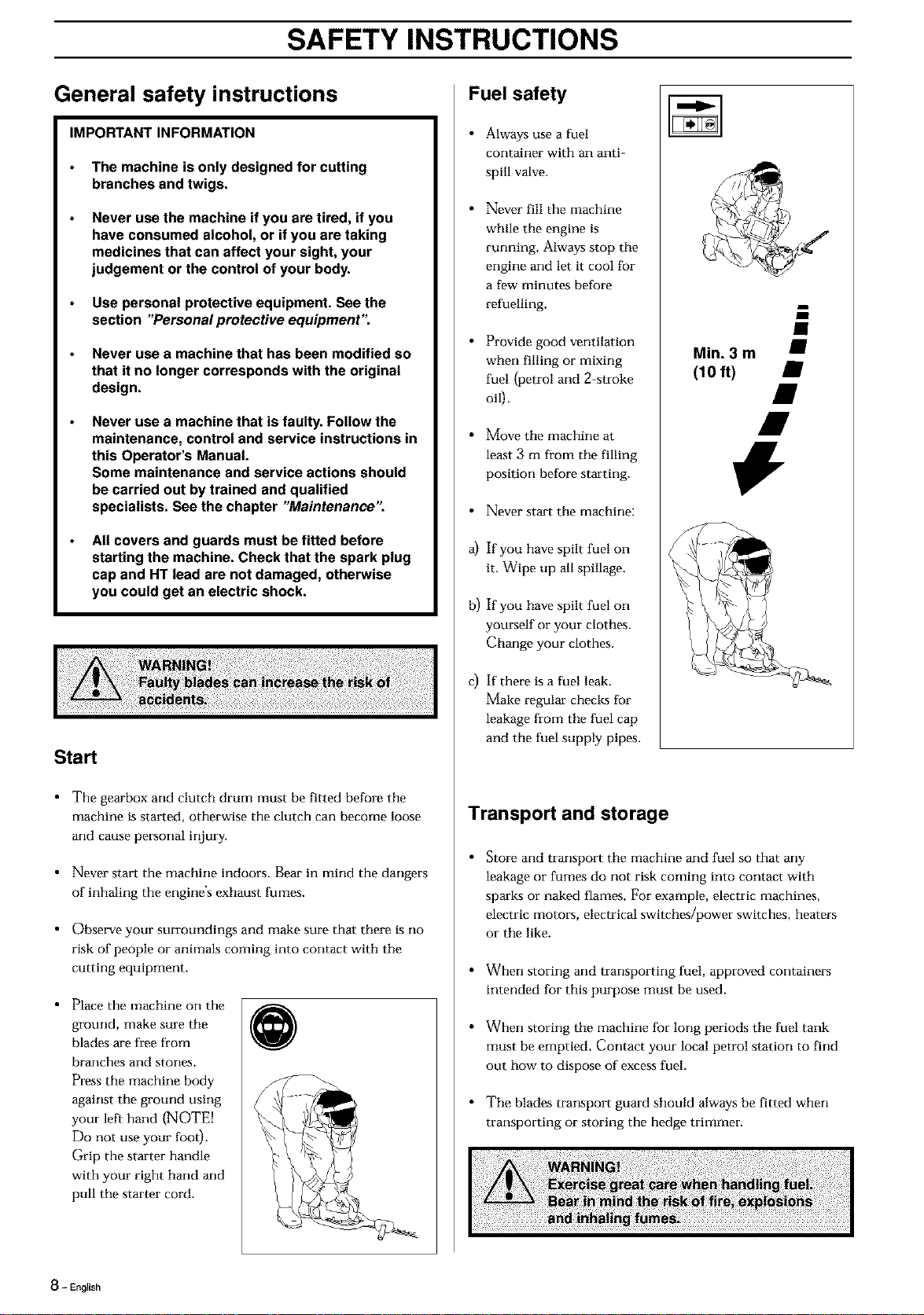
• Place the machine on the
ground, make sure the
blades are free from
branches and storms.
Press the machine body
against the ground using
your left hand (NOTE!
Do not use your foot).
Grip the starter handle
with your right hand and
pull the starter cord.
@
Fuel safety
• Always use a fuel
container with an anti-
spill valve.
• Never fill the machine
while the engine is
rurming. Always stop the
engine and let it cool for
a few minutes before
refuelling.
• Provide good ventilation
when filling or mixing
fuel {petrol and 2-stroke
oil).
• Move the machine at
least 3 m from the filling
position before starting.
• Never start the machine:
a) If you have spilt fuel on
it. Wipe up all spillage.
b) If you have spilt fuel on
yourself or your clothes.
Change your clothes.
c) If there is a fuel leak.
Make regular checks for
leakage from tile fuel cap
and the fuel supply pipes.
Min. 3 m j
(10 ft)
Transport and storage
Store and transport the machine and fuel so that any
leakage or fumes do not risk coming into contact with
sparks or naked flames. For example, electric machines,
electric motors, electrical switches/power switches, heaters
or the like.
When storing and transporting fuel, approved containers
intended for this purpose must be used.
When storing the machine for long periods the fuel tank
must be emptied. Contact your local petrol station to find
out how to dispose of excess fuel.
The blades transport guard should always be fitted when
transporting or storing the hedge trimmer.
8 - English

SAFETY INSTRUCTIONS
Safety instructions when using the hedge
trimmer
NOTE[ Read the Operator's Manual carefully before using
the hedge trimmer.
Personal protection
• Always weal- boots, and tile
other safpty equipment
described in the section
"Personal protective
equipment ".
• Always wear working
clothes and thick, long
trousers.
• Never wear loose fitting
clothes or jewellery
• Secure hair so it is above
shoulder level.
Protective instructions regarding the
surroundings
• Never allow children to use
the machine.
• Ensure no one comes
within 15 metres while
working.
• Never allow anyone to use
the machine without first
being absolutely sure that
they understand tile
contents of the Operator's
Manual.
• Never work on a ladder,
stool or any other raised
position that is not fully
secured.
Protective instructions while working
Always ensure you have a
safe arm firm working
position.
Always use both harms to
hold the machine. Hold
the machine in front of
you.
Use your left hand to
operate the throttle.
Make sure that your
hands arm feet cannot
come into contact with
the blades when the
engine is running.
Watch out for stumps of
branches that can be
thrown out during
cutting.
When the engine is
switched off keep your
harms arm feet away from
the blades until they have
stopped.
@
Do not cut too close to the ground. Storms arm other objects
can be throwrL
Check the hedge you intend to trim for foreign objects such
as electricity cables, insects and animals, etc, and for other
objects that could damage the cutting attachment, such as
metal items.
If any object is hit or if vibrations occur stop tile machine
immediately. Remove the spark plug cable from the spark
plug. Check that the machine is not damaged. Repair any
damage.
If anythingjams in the blades while you are working, switch
off the engine and wait until it has stopped completely
before cleaning the blades. Disconrmct the HT lead from
the spark plug.
English - 9

SAFETY INSTRUCTIONS
Protective instructions when
work is completed
• The transport guard should always be fitted to the blades
when the machine is not in use.
• Ensure tile blades have stopped and remove the spark plug
cable from the spark plug before carrying out cleaning,
repairs or an inspection.
• Always wear heavy duty
gloves when repairing the
blades. The blades are
extremely sharp and can
easily causes cuts.
• Store the machine out of
reach from children.
Only use original spare
parts when carrying out
repairs.
Basic working
techniques
• When cutting the sides of a
hedge, work from the
bottom upwards. When
cutting horizontally, work
from right to left.
• Adjust the throttle setting
to suit the load.
• When trimming a hedge
the engine should always
be turned away from the
hedge.
• The hedge trimmer should
be held as close to the body
as possible to get the best
balance.
• Make sure that the tip does
not touch the ground.
• Do not ttTf to force the
work, but move at a steady
speed so that all the stems
are cut evenly.
10- English

WHAT IS WHAT?
/
What is what on the hedge trimmer?
1. Operator's Manual
2. Grease nipple
3. Gearbox
4. Blades
5. Hand guard
6. Handle
7. Cylinder cover
8. Starter handle
9. Fuel cap
10. Fuel tank
11. Air purge
12. Choke
13. Throttle trigger lock
14. Throttle trigger
15. Stop switch
16. Air filter cover
17. Spark plug spanner
18. Allen key
19. Blade cover (Transport)
20. Catcher (accassory)
En_,,h-11

FUEL HANDLING
Fuel mixture
NOTE!
The machine is fitted with a two-stroke engine and must
always be run on a mixture of gasoline and two-stroke oil. It is
important to measure the quantity of oil accurately, to ensure
the correct mixture ratio. Small discrepancies in the amount of
oil have a great bearing on the proportions of the fuel mixture
when mixing small amounts of fuel.
Gasoline
NOTE!
Always use an oil-mixed
quality gasoline (at least 8"/
octane). If your machine is
equipped with a catalytic
converter, ( an unleaded, oil
mixed quality gasoline
should always be used. A
leaded gasoline will destroy
the catalytic converter.
• This engine is certified to
operate on unleaded
gasoline.
• The lowest recommended
octane rating is 87. If you
run the engine on lower
octane rating than 87 so-
called "knocking" can
occur. This leads to an
increased engine
temperature, which can
result in a serious engine
breakdown.
• When working at
continuous high revs a
higher octane rating is
recommended.
6
6
Two-stroke oil
• For the best results use HUSQVARNA two-stroke oil,
which has been specially developed for HUSQVARNA's
small, two-stroke engines. Mixing ratio 1:50 (2%).
• Never use two-stroke oil intended for water cooled outboard
motors, so-called outboard motor oil.
• Never use oil intended for four-stroke engines.
Mixture
• Always mix gasoline and oil in a clean container intended for
fuel.
• Always start by filling half the quantity of gasoline required.
Then add the entire oil quantity. Mix (shake) the fuel
mixture. Fill the remaining quantity of gasoline.
• Mix (shake) the fuel mixture carefully before filling in the
machirm's fuel tank.
• Do not mix more than max. one month's supply of fuel.
• If the machine is not used for a long period of time, the fuel
tank should be emptied and cleaned.
• This engine is certified to operate on unleaded gasoline.
Fuelling
• Clean around the fuel cap.
Contamination in the tank
can disrupt operations.
• Ensure that the fuel is well
mixed by shaking the
container before filling the
tank.
Gasoline Oil
2%(1:50)
Lit. Lit,
5 0,10
10 0,20
15 0,30
20 0,40
US US
gallon fL oz.
1 2 1/2
2 1/2 6 1/2
5 12 7/8
Min. 3 m i
(10 ft) •
#
12 - English

START AND STOP
Control before starting
• Inspect the working area. Remove objects that can be
thrown.
• Check the blades. Never
use blades that are dull,
cracked or damaged.
• Check that the hedge
trimmer is in full
working order. Check
that all nuts and bolts are
tightened correctly.
• Make sure the gearbox is lubricated correctly. See the
section "Lubricating the bladed'.
• Ensure the blades always stop when tile engine is idling.
• Only use the machine for what it is intended for.
• Ensure that the handle and safety functions are in order.
Never use a machine that lacks a part or has been modified
outside of the specifications.
Start and stop
Start
Cold engine
IGNITION:
Set the stop switch to the
start position.
CHOKE:
Set the choke control in the
choke position (A).
The choke position is also
the automatic start throttle
position.
AIR PURGE:
Press the air purge
diaphragm repeatedly until
fuel begins to fill the
diaphragm. The diaphragm
need not be completely
filled.
@
A
Warm engine
IGNITION:
Set the stop switch to the
start position.
CHOKE:
Set the choke control in the
choke position and then
back again to its original
position (B)
In this way only the start
throttle is applied with no
choke.
AIR PURGE:
Press the air purge
diaphragm repeatedly until
fuel begins to fill the
diaphragm. The diaphragm
rmed not be completely
filled.
@
Press the machine body
against the ground using your
left hand (NOTE! Do not use
your foot). Grip the starter
handle with your right hand
and slowly pull the starter
cord out until you feel some
resistance, (the starter hooks
grip) now quickly and
powerfully pull the cord.
Immediately press the choke
control in when the engine
fires and repeat until the
engine starts. When the
engine starts, quickly apply
full throttle and the start
throttle will automatically
disengage.
@
NOTE! Do not pull the starter cord out completely and do
not release the starter cord from the fully extended position.
This can damage the hedge trimmer.
Stop
The engine is stopped by
switching the ignition off
using the stop switch.
English - 1 3

MAINTENANCE
Carburetor
Your Husqvarna product has been designed and manufactured
to specifications that reduce harmful emissions.
After your unit has been run 8-10 tanks of fuel the engine has
broken irL To ensure, that your unit is at peak performance and
producing the least amount of harmful emissions after break
in, have your authorized servicing dealer, who has a revolution
counter at his disposal, to adjust your carburetor for optimum
operating conditions.
Operation
• Tbe carburetor governs
the engine's speed via the
throttle. Air/fuel is mixed
in the carburetor. The
air/fuel mixture, is
adjustable. To take
advantage of the engine's
optimal output the
adjustment must be
correct.
• The setting of the
carburetor means that
the engine is adapted to
local conditions, for
example, tile climate,
altitude, gasoline and the
type of ?-stroke oil.
L
\
\
\
H
• The carburetor is equipped with three adjustment possibili-
ties:
H = High speed needle
L= Low speed needle
T = Idle speed adjuster screw
• The fuel quantity in re.lation to the air flow permitted by
the throttle opening is adjusted using the L and H-needles.
Turning the needles clockwise gives a leaner fuel mixture
(less fuel) and turning them anti-clockwise gives a richer
fuel mixture (more fuel). A leaner mixture gives high revs
while a richer mixture give less revs.
• The T-screw regulates the position of the throttle while the
engine is idling. Turning the screw clockwise gives a higher
idling speed while turning it anti-clockwise gives a lower
idling speed.
Basic setting
• The carburetor is set to its basic setting when test run at the
factory. The basic setting is richer than the optimal setting
and should be kept during the machine's first working
hours. Thereafter the carburetor should be firmly adjusted.
Fine adjustment should be carried out by a skilled
technician.
NOTE! If the blades move while the engine is idling the T-
screw should be turned anti-clockwise until the blades stop.
Recommended idling speed is: 2 700 rpm.
Recommended max. speed: See "tachnicaldata':
i_i!iii!¸!!iiiii_i!!ili!i!i_iiiiiis__ i_!ii_ksh 6_i¸i!0_;il__:i_S_!it_ei!!ii!!!ii:il_ii!!!i!iiiii!i!_iiiliii_!
Fine adjustment
• Wben the macbine bas been "run-in" the carburetor should
be finely adjusted. The fine adjustment should be carried
out by qualified person. First adjust the L-jet, then the
idling screw T and then the H-jet.
Conditions
• Before any adjustments are made the airfilter should be clean
and the airfilter cover fitted. Adjusting the carburetor while
a dirty airfilter is in use will result in a leaner mixture when
the filter is finally cleaned. This can give rise to serious
engine damage.
• Carefully turn the L and H needle to the mid point between
fully turned in and fully turned out..
• Do not attempt to adjust the needles beyond the stops as
damage can occur.
• Now start tbe machine according to the starting instructions
and run it warm for 10 minutes.
NOTE! If the blades move, the T screw should be turned
counter=clockwise until the blades stop.
Low speed needle L
Try to find the bighest idling
speed, turning the low speed
needle L clockwise
respectively counter-
clockwise. When the highest
speed has been found, turn
the low speed needle L 1/4
turn counter-clockwise.
NOTE! If the blades move
when the engine is idling,
turn the idling speed screw T
counter-clockwise until the
blades stop.
L
\
\
1 4 - English

MAINTENANCE
Adjusting the idle speed, T
AdJust the idling speed with
the screw T, if it is necessary
to readjust. First turn the idle
speed adjusting screw T
clockwise until the blades
stalt moving. Then turn the
screw anti-clockwise until the
blades stop. The idle speed is
correctly adjusted when the
engine runs smoothly in
every positiorL There should
be a good margin to the
speed when the cutters start
to move. The cutters should
not move when the choke
control is in the start throttle
position.
T
WARNING! Contact your dealer/setwice workshop if the idle
speed setting cannot be adjusted so that the blades stop. Do
not use the machine until it has been properly adjusted or
repaired.
High speed needle H
The high speed needle affects
the machine's power, speed,
temperature and fuel
consumption. A too lean
adjustment on the high speed
needle H (the high speed
needle H is screwed in too
much) gives a too high speed
resulting in engine damage.
Do not allow the engine to
run at full speed for more
than i0 seconds.
Apply full throttle and turn
the high speed needle H
slowly anticlockwise until the
engine runs unevenly. The
high speed needle H is then
turned slowly clockwise a
little until the engine runs
smoothly
Note the engine should be
run unloaded when adjusting
the high speed needle.
The high speed needle is
adjusted correctly when the
H
machine "splatters" a little. If the machine smokes heavily at
the same time as it "splatters" heavily the adjustment is too
rich.
NOTE! For optimum setting of the carburetor, contact a
qualified servicing dealer who has a revolution counter at his
disposal.
Correctly adjusted carburetor
When the carburettor is corre,ctly adjusted the machine will
accelerate without hesitation and the engine will splutter a
little at maximum speed. In addition, the cutters must not
move when idling or when the choke control is in the start
position. If the low speed needle is set for too lean a mixture it
can cause starting problems and poor acceleratiorL
A too lean adjusted high speed needle H gives lower power =
less capacity, bad acceleration and/or damage to the engine.
A too rich adjustment of the two speed needles L and H gives
acceleration problems or too low working speed.
English - 1 5

MAINTENANCE
Muffler
NOTE!
Some mufflers are fitted with a catalytic converter. See
"Technicaldata"to see whether you clearing saw is fitted with a
catalytic convelter.
The muffler is designed to
dampen the noise level and
to direct the exhaust fumes
away from the user. The
exhaust fumes are hot and
can contain sparks, which
can re.sult in fire if the
exhaust fumes are directed
towards a dry and
inflammable material Some
mufflers are equipped with a
special spark arrest screerL If
your machine is fitted with
this type of screen it should
be cleaned regularly. This is
done using a wire brush. On
mufflers without a catalytic
converter the screen should
be cleaned weekly, or
replaced if necessary. On
mufflers fitted with a
catalytic converter the screen
should be checked and
cleaned monthly. If the
screen is damaged it should
be replaced. If the screen is
frequently blocked, this can
be a sign that the function of
the catalytic converter is
impaired. Contact your
dealer to inspect the muffler.
A blocked screen will cause
the engine to overheat
re.sulting in damage to the
cylinder and pistorL Also see
under "A_aintenan_'_
NOTE!
Never use a machine with a
defective muffler.
Cooling system
To maintain as low opera-
ting temperature as possible
the engine is equipped with
a cooling system.
The cooling system consists
of:
1. An air intake on the
starter unit.
2. Cooling fins on the
flywheel.
3. Cooling fins on the
cylinder
4. Cylinder cover (leads
cold air onto the cylin-
der).
Clean the cooling system
using a brush at least once a
week, in difficult conditions
more often.
1 2
A dirty or blocked cooling system leads to the engine
overheating resulting in damage to the cylinder and piston.
Spark plug
The condition of the spark plug is affected by:
• An incorrect carburetor setting.
• An incorrect fuel mixture (too much or faulty oil).
• A dirty air filter.
These factors cause deposits on the spark plug electrode that
may result in malfunction or starting difficulties.
If the machine is low on
power, difficult to start or
runs poorly while idling
always check the spark plug
first before taking other
action.
If the spark plug is dirty,
clean it and at the same time
check that the electrode gap
is 0.5 mm. The spark plug
should be changed after
about one month of
operation or earlier if
necessm_y.
NOTE! Always use the
recommended type of spark
plug. An incorrect spark
plug can damage the
cylinder/piston.
1 6 - English

MAINTENANCE
Air filter
The air filter (A) should be
cleaned regularly removing
dust and dirt to avoid:
• carburetor malfunction
• starting problems
• reduced engine power
• unnecessary wear to
engine parts
• abnormal fuel consump-
tion
Clean the filter after every
25 hours or more regularly
if operating conditions are
exceptionally dusty.
Cleaning the air filter
Dismantle the air filter cover (B) and remove the air filter.
Wash in clean, warm soapy water. Ensure that the filter is dry
before refitting.
An air filter used for a long period of time can never be cleaned
completely. Therefore it is necessary to replace the filter from
time to time with a new filter. A damaged air filter must always
be replaced.
If the machine is used in dusty conditions the air filter
should be soaked in oil, see the section on "Oiling the air
filteF.
Oiling the air filter
Always use HUSQVARNA
filter oil, order no. 503 47
73-01. The filter oil contains
a solvent to make it spread
evenly through the filter. You
should therefore avoid skin
contact. Put the filter in a
plastic bag and the pore- the
filter oil over it. Knead the
plastic bag to distribute the
oil. Squeeze the excess oil out
of the filter inside the plastic
bag and pour off the excess
before fitting the filter on the
machine. Never use common
engine oil. This would drain
through the filter quite
quickly and collect in the
bottom.
Gearbox
There isa grease nipple (A)
on the gearbox. Use a grease
gun to top up with grease.
This should be carried out
after approximately every 20
working hom_. Use
Husqvarna special grease,
No. 503 98 96-01.
Note that the gearbox must
not be filled completely with
grease. The grease expands
as the machine heats up
during operation. If the
gearbox was completely
filled with grease it could
damage the seals and lead to
leakage.
The lubricant in the gearbox
does not normally need to be
replaced other than with
repair.
Cleaning and
lubrication
After you have used the
machine clean any resin and
plant re.sidue from the blades
using cleaning agent 531 00
60-75 (UL22).
Always lubricate the blade
runners with special grease
531 00 60-74 (UL 2001)
before use.
A
En_l_,h-17

MAINTENANCE
Maintenance schedule
Below you will find some general mair_termnce instructions.
Daily maintenance
• Check throttle trigger and throttle trigger lockout function.
• Check stop switch function.
• Check that the blades do not rotate while idling or when the
choke is in the start position.
• Clean the exterior of the machine.
• Check that the harness is undamaged.
• Check that the blade is properly centred, sharp, and without
cracks.
• Check the hand guard for cracks and chips or damage.
Replace if necessary.
• Check that tile blade screws are sufficiently tightened (See
the section "Control, maintenance and service of the machine's
safety equipment _).
• Make sure that the blade transport guard is undamaged and
that it can be securely fitted.
• Check that nuts and screws are sufficiently tightened.
• Check for fuel leaks.
Weekly maintenance
• Check the starter, especially cord and return spring.
• Make sure that the vibration damping elements are not
damaged.
• Clean tile carburetor area.
• Clean the exterior of the spark plug.
• Remove it and check the electrode gap.
• Adjust it to 0,5 mm (.020"), or change the spark plug.
• Clean the cooling fins on the cylinder and check that the air
intake at the starter is not clogged.
• Fill the gearbox with grease. This should be carried out after
approximately every 20 working hours.
• Clean tile air filter.
• Clean or replace the muffler's spark arrest screen (not on
mufflers with a catalytic converter).
Monthly maintenance
• Clean the fuel tank.
• Clean tile exterior of the carburetor and the space around it.
• Clean the fan and the space around it.
• Check fuel hose for cracks or other damage. Change if
necessary.
• Change fuel filter in fuel tank.
• Check clutch, clutch spring and clutch drum for wear.
Change if necessary.
• Check electrical wires and connections.
• Change tile spark plug.
• Change the airfilter.
• Check and clean the muffler's spark arrest screen if necessary
(only mufflers with a catalytic converter).
1 8 - EngEish

TECHNICAL DATA
Technical data 326HS75 326HS99
Engine
Displacement, cu inlcm 3
Cylinder bore, inch/mm
Stroke length, inch/mm
Idling speed, rpm
Recommended max. speed rpm
Max. engine output, acc. to ISO 8893
Catalytic converter muffler
Speed-regulated ignition system
1,50124,5 1,50/24,5
1,34134 1,34/34
1,06127 1,06/27
2 700 2 700
11 000 11 000
0,9 kW / 9 000 rpm 0,9 kW / 9 000 rpm
Yes Yes
Yes Yes
Ignition system
Manufacturer/type of ignition system
8park plug
Electrod gap, inch/mm
Walbro MB Walbro MB
Champion RCJ 6Y Champion RCJ 6Y
0,02/0,5 0,02/0,5
Fuel lubrication system
Manufacturer/type of carburetor
Fuel tank capacity, U8 pint/litres
Zama C1Q Zama C1Q
1,06/0,5 1,06/0,5
Weight
Weight without fuel, LBS/kg
12,3/5,6 13,0/5,9
Sound levels
(See note i)
Equivalent sound pre.ssurelevel at
the user's ear, measured according to EN
ISO 11806 and ISO 7917, dB(A):
96 97
Vibration levels
Vibration levels on the handles measured
according to EN ISO 11806 and I80 7916,
m/s 2
Idling, rear/front handles:
Max. speed , rear/front handles:
3,3/3,6 3,3/3,6
7,1/6,2 7,1/6,2
Blades
Length, ram: 720 1 000
Blade speed, cut/min: 4 695 4 695
Note 1: Equivalent sound pressure level is calculated as the time-weighted energy total for sound pressure levels under various
working conditions with the following time distribution: 1/2 idle and 1/2 max. speed.
English - 1 9

EMISSION CONTROL WARRANTY STATEMENT
YOUR WARRANTY RIGHTS AND
OBLIGATIONS
The EPA (U.S. Environmenta! Protection Agency), CARB
(California Air Resources Board) and Husqvarna Forest & Garden
are pleased to explain the emissions control system warranty on
your 2001and later small off-road engine. In U.S., new small off
road engines must be designed, built and equipped to meet the
federal or California stringent anti-smog standards, t tusqvarna
Forest & Garden must warrant the emission control system on
your small off road engine for the periods of time listed below
provided there has been rio abuse, neglect or improper
maintenance of your small offroad engine.
Your emission control system includes parts such as the carburetor,
the ignition system and catalytic converter.
W'here a warrantable condition exists, t tusqvarna Forest & Garden
will repair your small off road engine at rio cost to you including
diagnosis, parts and labor.
MANUFACTURER'S WARRANTY
COVERAGE
The 2001 and later small off road engines are warranted for two
years. If any emission related part on your engine is defective, the
part will be repaired or replaced by Husqvarna Forest & Garden.
OWNER'S WARRANTY
RESPONSIBILITIES
Asthe small offi road engine owner, you are responsible for the
performance of the required maintenance listed in your Owner's
Manual. Husqvarna Forest & Garden recommends that you retain
all receipts covering maintenance on your small off road engine,
but tIusqvarna Forest & Garden cannot deny warranty solely for
the lack of receipts or for your failure to ensure the performance of
all scheduled maintenance.
As the small off-road engine owner, you should, however, be aware
that Husqvarna Forest & Garden may deny you warranty coverage
if your small off road engine or a part has failed due to abuse,
neglect, improper maintenance or unapproved modifications.
You are responsible for presenting your small off road engine to a
t tusqvarna Forest & Garden authorized servicing dealer as soon as
a problem exists. The warranty repaFs should be completed in a
reasonable amount of time, not to exceed 30 days.
If you have any questions regarding your warranty rights and
responsibilities, you should contact your nearest authorized
servicing dealer or call Husqvarna Forest & Garden at 1-800-487-
5963.
WARRANTY COMMENCEMENT DATE
The warranty period begins on the date small offi road engine is
delivered.
LENGTH OF COVERAGE
t tusqvarna Forest & Garden warrants to the initial owner and each
subsequent pro'chaser that the engine is free from defects in
materials and workmanship which cause the failure of a warranted
part for a period of two yem_.
WHAT IS COVERED
REPAIROR REPLACEMENTOF PARTS
Repair or replacement of any warranted pa_t will be performed at
no charge to the owner at an approved tlusqvarna Forest &
Garden servicing dealer.
If you have any questions regarding your warranty rights and
responsibilities, you should contact your nearest authorized
servicing dealer or call tlusqvarna Forest & Garden at 1-800-487-
5963.
WARRANTY PERIOD
Any warranted part which is not scheduled for replacement as
required maintenance, or which is scheduled only for regular
inspection to the effect of "repair or replace as necessa W" shal! be
warranted for 2 years. Any warranted part which is scheduled for
replacement as requFad maintenance shall be warranted for the
period of time up to the first scheduled replacement point for that
part.
DIAGNOSIS
The owner shall not be charged for diagnostic labor which leads to
the determination that a warranted part is defective, if the
diagnostic work is performed at an approved t {usqvarna Fo_'ast &
Garden servicing dealer.
CONSEQUENTIAL DAMAGES
t {usqvarna Forest & Garden may be liable for damages to other
engine components caused by the failure of a warranted pa_t still
under warranty.
WHAT IS NOT COVERED
All failm'es caused by abuse, neglect or improper maintenance are
not covered.
ADDON OR MODIFIED PARTS
The use of add-on or modified pm_s can be grounds for
disallowing a warranty claim. Husqvarna Forest & Garden is not
liable to cover failures of warranted parts caused by the use of add-
on or modified parts.
HOW TO FILE A CLAIM
If you have any questions regarding your warranty rights and
responsibilities, you should contact your nea_'est authorized
servicing dealer or call Husqvarna Forest & Garden at 1-800-487-
5963.
WHERE TO GET WARRANTY SERVICE
Warranty services or repairs shall be p_'ovided at all I tusqvarna
Forest & Garden authorized servicing dealers.
MAINTENANCE, REPLACEMENT AND
REPAIR OF EMISSION-RELATED PARTS
Any Husqvarna Forest & Garden approved replacement part used
in the performance of any warranty maintenance or _epairs on
emission-related parts, wil! be provided without charge to the
owner if the part is under warranty.
EMISSION CONTROL WARRANTY
PARTS LIST
1. Carburetor and internal parts
2. Intake pipe, airfilter holder and carburetor bolts.
3. Airfilter and fuelfilter covered up to maintainance schedule.
4. Ignition System
a) Spark Plug, covered up to maintenance schedule
b) Ignition Module
5. Muffler with catalytic converter
MAINTENANCE STATEMENT
The owner is responsible for the performance of all required
maintenance, as defined in the operator's manual.
20 - English


114 O0 15-93
IIIIIIIIIIIIIIIIIIIIIIIII _oo_o,