Loading ...
Loading ...
4K Ultra HD Active
Deterrence Security Camera
Quick Start Guide
www.lorex.com
English Version 1.0
E891AB Series
E891AB_QSG_EN_R1
• 4K Ultra HD Bullet IP Camera
• Mounting Kit*
• Ethernet Extension Cable with Pre-attached RJ45 Cable Gland*
* Per camera in multi-camera packs.
Package Contents
ATTENTION:
It is recommended to connect the camera to the NVR or an external PoE switch. If using a DC power
adapter (not included) with the camera, a REGULATED power supply is REQUIRED for use with this
camera. Use of a non-regulated, non-conforming power supply can damage this product and voids the
warranty.
• Use the camera only with compatible Lorex NVRs.
• Read this guide carefully and keep it for future reference.
• Follow all instructions for safe use of the product and handle with care.
• Use the camera within given temperature, humidity and voltage levels noted in the camera’s
specifications.
• Do not disassemble the camera.
• Do not point the camera directly towards the sun or a source of intense light.
• Use only a regulated power supply with the product (optional). Use of a non-regulated, non-
conforming power supply can damage the product and void the warranty.
• Periodic cleaning may be required. Use a damp cloth only. Do not use any harsh, chemical-based
cleaners.
• Check the packaging of the included cable to verify cable grade based on model number.
CBL605U: The supplied cable is rated for surface and in-wall mounting. CBL100C5: The supplied
cable is rated for surface mounting only. Cables for in-wall and floor-to-floor installations are
sold separately (CMR type). These and other cables are available at lorex.com.
Safety Precautions
Need Help?
Visit us online for up-to-date software
and complete instruction manuals
Click on the Downloads tab
4
Visit lorex.com
Search for the model
number of your product
Click on your product
in the search results
3
2
1
Copyright © 2019 Lorex Corporation
As our products are subject to continuous improvement, Lorex reserves the right to modify product
design, specifications and prices, without notice and without incurring any obligation. E&OE. All rights
reserved.
Dimensions
7.3” / 187mm3.0” / 75mm
• For a full list of compatible recorders, visit lorex.com/compatibility.
• To ensure that you are viewing camera video in full 4K resolution (4K monitor required),
check the video output resolution of your recorder. For full instructions, see your recorder’s
documentation at lorex.com.
• Not intended for submersion in water. Installation in a sheltered location recommended.
• This camera includes an Auto Mechanical IR Cut Filter. When the camera changes between Day/
Night viewing modes, an audible clicking noise may be heard from the camera. This clicking is
normal, and indicates that the camera filter is working.
Disclaimers
ATTENTION:
• Test your camera prior to selecting a permanent mounting location by temporarily connecting
the camera and cable to your NVR.
• Review the section “STEP 1: Important Installation Guidelines” above before choosing a
permanent mounting location.
Before Installing the Camera
• Decide whether to run the cables through
the wall / ceiling (drilling required) or
along the wall / ceiling.
• If you run the cables along the wall /
ceiling, you must run the cable through
the cable notch on the base. This will
keep the camera base flush to the
surface when mounted.
Cable Notch
To install your camera:
1. Use the included mounting template to mark holes for the screws. Drill
holes for the mounting screws.
NOTE: Insert the included drywall anchors if you are installing the camera
in drywall.
2. Connect cables as shown in the section “Connecting the Camera”.
3. Feed the cable through the mounting surface or cable notch and mount
the camera stand to the surface using the provided screws.
4. Use a Philips head screwdriver (not included) to loosen the adjustment
screws shown below. Adjust the camera position as needed:
A. Rotate the camera
base 360°.
B. Tilt the camera on
the stand up to 90°.
C. Twist the camera
around the stand 360°.
A B C
5. Tighten the adjustment screws to secure the position.
6. Remove the vinyl film from the camera lens when your installation is
complete.
Additional Installation Tips:
• Point the camera where there is the least amount of obstructions (e.g., tree branches).
• Install the camera where vandals cannot easily reach.
• Secure cabling so that it is not exposed or easily cut.
• This camera is rated for outdoor use. Installation in a sheltered location is recommended.
STEP 1: Important Installation Guidelines
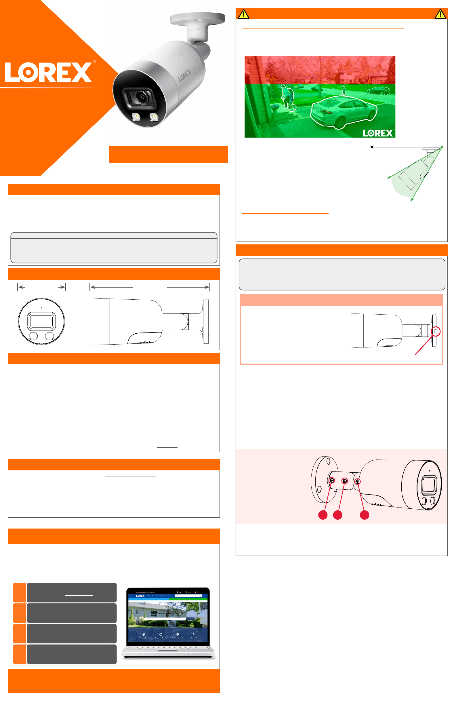
Optimizing Person and Vehicle Detection Accuracy:
• Angle the camera so that objects of interest appear in the bottom ⅔ of the camera
image.
• Choose a location where objects of interest will be no further than 50ft (~15m) from
the camera.
Optimal accuracy
for objects within
50ft (~15m) and in
the bottom ⅔ of the
image.
Lower accuracy for
objects further away
than 50ft (~15m) and/
or in the top ⅓ of the
image.
• Angle the camera between 30~60° down from the
level position.
• Install the camera between 8-16ft (2.5-5m) off of
the ground.
STEP 2: Installing the Camera
Level position (i.e., ceiling)
Optimal
angle
range
NOTE: Accuracy of person and vehicle detection will
be influenced by multiple factors, such as the object’s
distance from the camera, the size of the object, and
the height and angle of the camera. Night vision will
also impact the accuracy of detection.
Loading ...