Loading ...
Loading ...
Loading ...
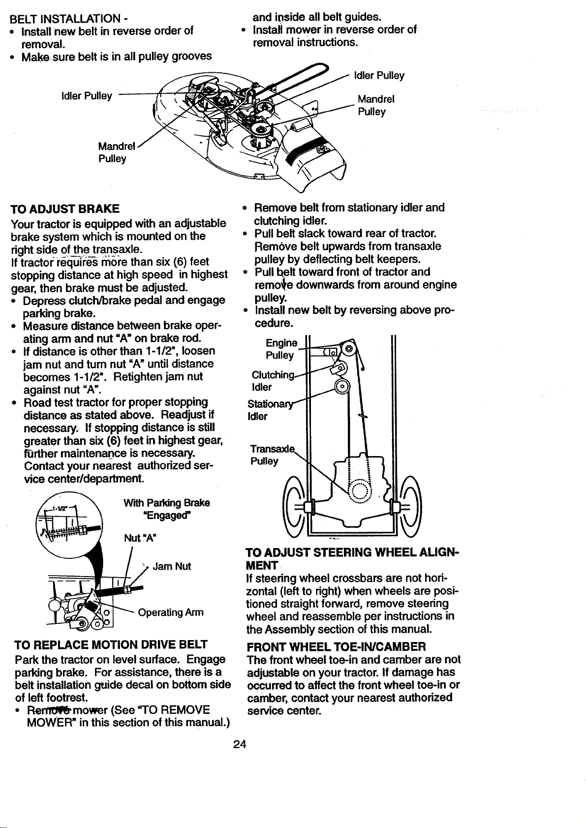
BELTINSTALLATION-
• Installnewbelt in reverseorderof
removal.
• Makesure belt isin allpulley grooves
Idler Pulley
and inside all belt guides.
Install mower in reverse order of
removal instructions.
Idler Pulley
Mandrel
Pulley
Mandrel
Pulley
TO ADJUST BRAKE
Your tractor is equipped with an adjustable
brake system which is mounted on the
right side of the transaxle.
If tractor requires more than six (6) feet
Remove belt from stationary idler and
clutching idler.
Pull belt slack toward rear of tractor.
Rembve belt upwards from transaxle
pulley by deflecting belt keepers.
stopping distance at high speed in highest
gear, then brake must be adjusted.
• Pull belt toward front of tractor and
remo_e downwards from around engine
Depress clutch/brake pedal and engage • pulley.
parking brake. Install new belt by reversing above pro-
Measure distance between brake oper- cedure.
ating arm and nut =A" on brake rod. Engine_ II
If distance is other than 1-1/2", loosen Pulley I_ II
jam nut and tum nut "A" until distance II
Clutching'_'l_ _, t II
becomeSagainstnutl"l/2"'=A".Retightenjam nut Idler i II
Road test tractor for proper stopping StaUonary_ II I I II
distance as stated above. Readjust if Idler II ]_ I!
necessary. If stopping distance is still
greater than six (6) feet in highest gear,
f0rther maintenance is necessary. Transaxle, II I_A__!!
Contact your nearest authorized ear- Pulley __
vice centeddepartment.
With ParkingBrake
=Engaged=
Nut ."A" ---
TO ADJUST STEERING WHEEL ALIGN-
Jam Nut
Operating Arm
TO REPLACE MOTION DRIVE BELT
Park the tractor on level surface. Engage
parking brake. For assistance, there is a
belt installation guide decal on bottom side
of left footrest.
• Re--mower (See "TO REMOVE
MOWER" in this section of this manual.)
MENT
If steering wheel crossbars are not hori-
zontal (left to right) when wheels are posi-
tioned straight forward, remove steering
wheel and reassemble per instructions in
the Assembly section of this manual.
FRONT WHEEL TOE-IN/CAMBER
The front wheel toe-in and camber are not
adjustable on your tractor. If damage has
occurred to affect the front wheel toe-in or
camber, contact your nearest authorized
service center.
24
Loading ...
Loading ...
Loading ...