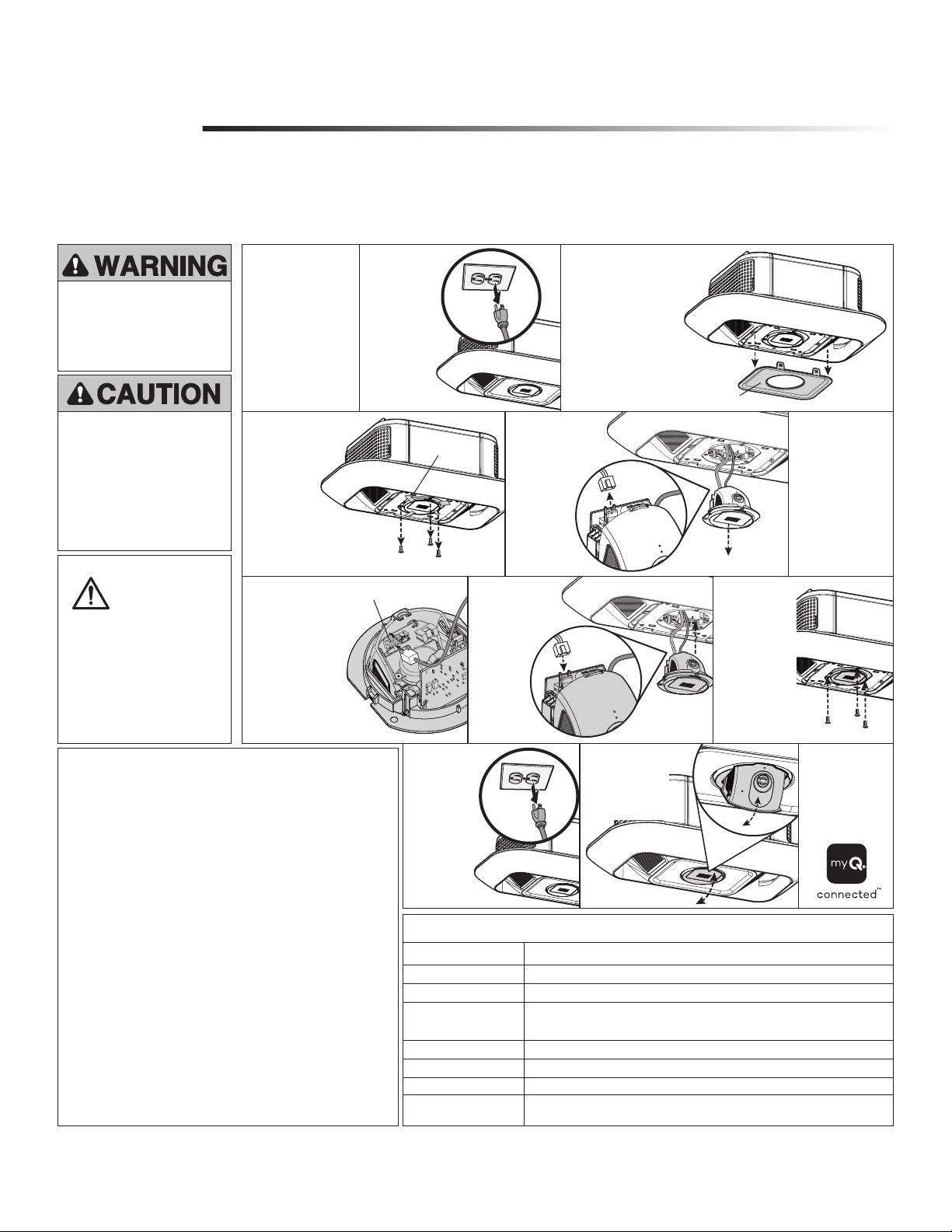
11.
Locate the notch
in the camera’s
opener and
pull down.
12.
Follow the myQ
®
App instructions
to add the new
camera to your
myQ
®
account.
10.
Reattach the
newbadge.
Reconnect
power and
battery, if used.
3.
Using a flat head
screwdriver,remove the
badge at the opener’s
bottom.
Badge is held in by four
clips, pull badge off.
Badge
9.
Align screw
holes and place
camera into
garage door
opener.
Fasten the
three screws
with a Phillips
screwdriver.
To prevent damage to the camera,
push the camera lens closed when
replacing, and hold it in place as
you remove securing hardware.
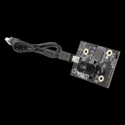
DO NOT touch the camera logic
board during installation.
ALWAYS wear protective gloves
and eye protection when changing
the battery or working around the
battery compartment.
Introduction
Installation
CAMERA SERVICE KIT REPLACEMENT
Model 041-0347-000
Your camera is accessible at the opener’s bottom side. After installing
the new camera, use your myQ
®
app to connect your new camera to
your myQ
®
account.
2.
Disconnect
power to the
garage door
opener, and
remove the
backup battery,
if used.
1.
Using the myQ app,
delete the garage
door opener from
the myQ account
before re-adding the
opener and camera
to the myQ account.
To prevent possible
SERIOUS INJURY or DEATH:
• Disconnect ALL electric
and battery power BEFORE
performing ANY service or
maintenance.
WARNING: This
product can
expose you to
chemicals including lead,
which are known to the
State of California to cause
cancer or birth defects or
other reproductive harm.
For more information go to
www.P65Warnings.ca.gov.
Camera LED Status Indicators
WHAT YOU SEE WHAT IT MEANS
Solid White Camera is powering up.
Flashing Blue Ready to be set up in the myQ
®
App.
Solid Blue Connected to your mobile device. You are not yet connected to the Internet. If this
persists after setup, check your home router and Internet. Connecting to Wi-Fi
®
and
connecting to the myQ
®
App.
Flashing Blue and Green Connecting to Wi-Fi and connecting to the myQ
®
App.
Solid Green Connected to the myQ
®
App.
Flashing Purple Receiving firmware updates.
Solid Red Camera thermal error state when the camera reaches high heat 60 °C temperature
and cools down.
Tools:
• Phillips Screwdriver
• Flat head Screwdriver
• Ladder
• Masking Tape (optional)
Hardware:
• Screw Qty. (3)
• Decorative Badge
• Camera
NOTICE: This device complies with part 15 of the FCC rules and
Innovation, Science and Economic Development Canada licence-exempt
RSSs. Operation is subject to the following two conditions: (1) this device
may not cause harmful interference, and (2) this device must accept any
interference received, including interference that may cause undesired
operation. Any changes or modifications not expressly approved by the
party responsible for compliance could void the user’s authority to operate
the equipment.
This device must be installed to ensure a minimum 20 cm (8 in.) distance
is maintained between users/bystanders and device.
This device has been tested and found to comply with the limits for a Class
B digital device, pursuant to part 15 of the FCC rules and Industry Canada
ICES standard. These limits are designed to provide reasonable protection
against harmful interference in a residential installation. This equipment
generates, uses and can radiate radio frequency energy and, if not
installed and used in accordance with the instructions, may cause harmful
interference to radio communications.
However, there is no guarantee that interference will not occur in a
particular installation. If this equipment does cause harmful interference
to radio or television reception, which can be determined by turning
the equipment off and on, the user is encouraged to try to correct the
interference by one or more of the following measures:
• Reorient or relocate the receiving antenna.
• Increase the separation between the equipment and receiver.
• Connect the equipment into an outlet on a circuit different from that to
which the receiver is connected.
• Consult the dealer or an experienced radio/TV technician for help.
The device for operation in the band 5150-5250 MHz is only for indoor
use to reduce the potential for harmful interference to co-channel mobile
satellite systems.
6.
Open camera
and remove the
three-pronged wire
harness that has
the black, green,
and white wires.
Rotate the
connector clip
backward before
removing the wire
harness.
Connector clip
7.
Open new camera
and place the
three-pronged wire
harness that has the
black, green, and
white wires.
Rotate connector
clip back into place
after reconnection.
Close camera.
5.
Remove the
two-pronged wire
harness with the
black and
white wires.
4.
Unscrew the
camera slowly
from the opener
housing by
removing the
three screws
with a Phillips
screwdriver.
TIP: Use masking tape to
hold the camera in place
as you remove screws.
Masking
Tape
8.
Connect the
two-pronged
wire harness
that has the
black and
white wires.
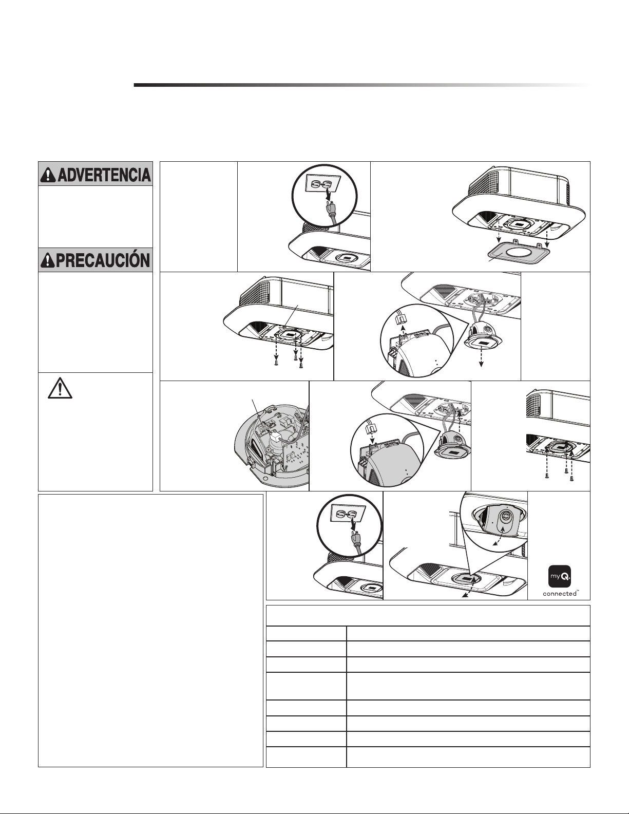
Para evitar daños a la cámara,
cierre el lente de la cámara cuando
la reemplace, y sosténgala en
el lugar al retirar los herrajes de
seguridad. NO toque el tablero
lógico de la cámara durante la
instalación.
Use SIEMPRE guantes protectores
y protección para la vista al
cambiar la batería o al trabajar
cerca del compartimiento de la
batería.
Introducción
Instalación
JUEGO DE SERVICIO DE LA CÁMARA DE REPUESTO
Modelo 041-0347-000
Se puede acceder a la cámara desde el lado inferior del abre-puertas.
Una vez instalada la cámara nueva, use la aplicación myQ
®
para conectar
la cámara a su cuenta myQ
®
.
Para evitar posibles LESIONES
GRAVES o la MUERTE:
• Desconecte TOTALMENTE
la corriente eléctrica y de la
batería ANTES de realizar
CUALQUIER servicio o
mantenimiento.
Indicadores de estado del LED de la cámara
LO QUE USTED VE LO QUE SIGNIFICA
Blanco sin parpadear La cámara se está encendiendo.
Azul parpadeante Preparada para configurarla en la aplicación myQ
®
.
Azul sin parpadear Conectada a su dispositivo móvil. Usted no está conectado a Internet. Si esto
persiste después de la configuración, revise el router y la conexión a Internet de su
casa. Conectándose a la red de Wi-Fi
®
y a la aplicación myQ
®
.
Azul y verde parpadeante Conectándose a la red de Wi-Fi y a la aplicación myQ
®
.
Verde sin parpadear Conectada a la aplicación myQ
®
.
Púrpura parpadeante Recibiendo actualizaciones de firmware.
Rojo sin parpadear El estado de error térmico de la cámara ocurre cuando la cámara alcanza una alta
temperatura de 60 °C y se enfría.
Herramientas:
• Destornillador estrella
• Destornillador de cabeza plana
• Escalera
• Cinta adhesiva de papel (opcional)
Accesorios de montaje:
• Cant. de tornillos (3)
• Insignia decorativa
• Cámara
AVISO: Este dispositivo cumple con la parte 15 de la reglamentación de
la FCC y los estándares RSS exentos de licencia de Innovación, Ciencia
y Desarrollo Económico de Canadá. La operación está sujeta a las dos
condiciones siguientes:(1) este dispositivo no puede causar interferencia
perjudicial, y (2) este dispositivo debe aceptar cualquier interferencia
recibida, incluyendo la interferencia que puede causar una operación no
deseable.
Cualquier cambio o modificación no expresamente aprobada por la parte
responsable del cumplimiento podría anular la autoridad del usuario para
operar el equipo.
Instalar este dispositivo de manera que quede una distancia mínima de 20
cm (8 pulg.) entre el dispositivo y los usuarios/transeúntes.
Este equipo ha sido verificado y cumple con los límites para un dispositivo
digital de Clase B, conforme con la Parte 15 de las normas de la FCC y
el estándar ICES de Industry Canada. Estos límites se establecen para
brindar un nivel razonable de protección contra interferencias perjudiciales
en instalaciones residenciales. Este equipo genera, usa y puede emitir
energía de radiofrecuencia. Si no se instala y utiliza de acuerdo con las
instrucciones podrá causar interferencia con comunicaciones radiales.
Aun así, no hay garantía de que no se produzcan interferencias en una
instalación particular. Si este equipo produce interferencia en la recepción
de radio o televisión, lo cual puede determinarse apagando y encendiendo
la unidad, el usuario debe tratar de corregir el problema por medio de lo
siguiente:
• Volver a orientar o reubicar la antena receptora.
• Aumentar la distancia entre el equipo y el receptor.
• Conectar el equipo en una salida de un circuito distinto del circuito al que
está conectado el receptor.
• Consultar con el distribuidor o con un técnico de radio/TV experimentado
para pedir ayuda.
El dispositivo para el funcionamiento en la banda 5150-5250 MHz es
solamente para uso en interiores a fin de reducir posibles interferencias
perjudiciales a los sistemas móviles por satélite de canal común.
ADVERTENCIA:
Este producto
puede exponerle
a productos químicos
(incluido el plomo), que a
consideración del estado de
California causan cáncer,
defectos congénitos u otros
daños reproductivos. Para
más información, visite
www.P65Warnings.ca.gov
11.
Localice la muesca
en el abridor de
la cámara y tire
hacia abajo.
12.
Follow the
myQ
®
Siga las
instrucciones de la
aplicación myQ
®
para agregar la
cámara nueva a su
cuenta myQ
®
.
10.
Vuelva a
colocar
la nueva
insignia.
Vuelva a
conectar la
alimentación
y la batería,
si se utilizan.
3.
Con un destornillador
de cabeza plana, retire
la insignia en
la parte inferior
del abridor.
La insignia se sujeta
con cuatro presillas.
Quite la insignia.
Insignia
9.
Alinee los
orificios de los
tornillos
y coloque
la cámara en el
abrepuertas
de garage.
Ajuste los tres
tornillos con un
destornillador
Phillips.
2.
Desconecte la
alimentación
del abrepuertas
degarage y
retire la batería
de respaldo, si
se utiliza.
1.
Mediante la aplicación
myQ, elimine el
abrepuertas de garaje
de la cuenta myQ antes
de volver a añadir
el abrepuertas y la
cámara a dicha cuenta.
6.
Abra la cámara
y retire el arnés
del cable de tres
puntas que tiene
los cables negro,
verde y blanco.
Gire la presilla del
conector hacia
atrás antes de
retirar el arnés de
cables.
Presilla del conector
7.
Abra la nueva cámara
y coloque el arnés del
cable de tres puntas
que tiene los cables
negro, verde y blanco.
Vuelva a girar la
presilla del conector
a su lugar de origen
después de la
reconexión.
Cierre la cámara.
5.
Retire el arnés
del cable de
dos puntas
que tiene los
cables negro
y blanco.
4.
Extraiga lentamente
lacámara de
la carcasa del
abridor al
retirar los tres
tornillos con un
destornillador
Phillips.
CONSEJO: use cinta
adhesiva para mantener
la cámara en su lugar mientras
retira los tornillos.
Cinta adhesiva
de papel
8.
Conecte el arnés
del cable de dos
puntas que tiene
los cables
negro y
blanco.
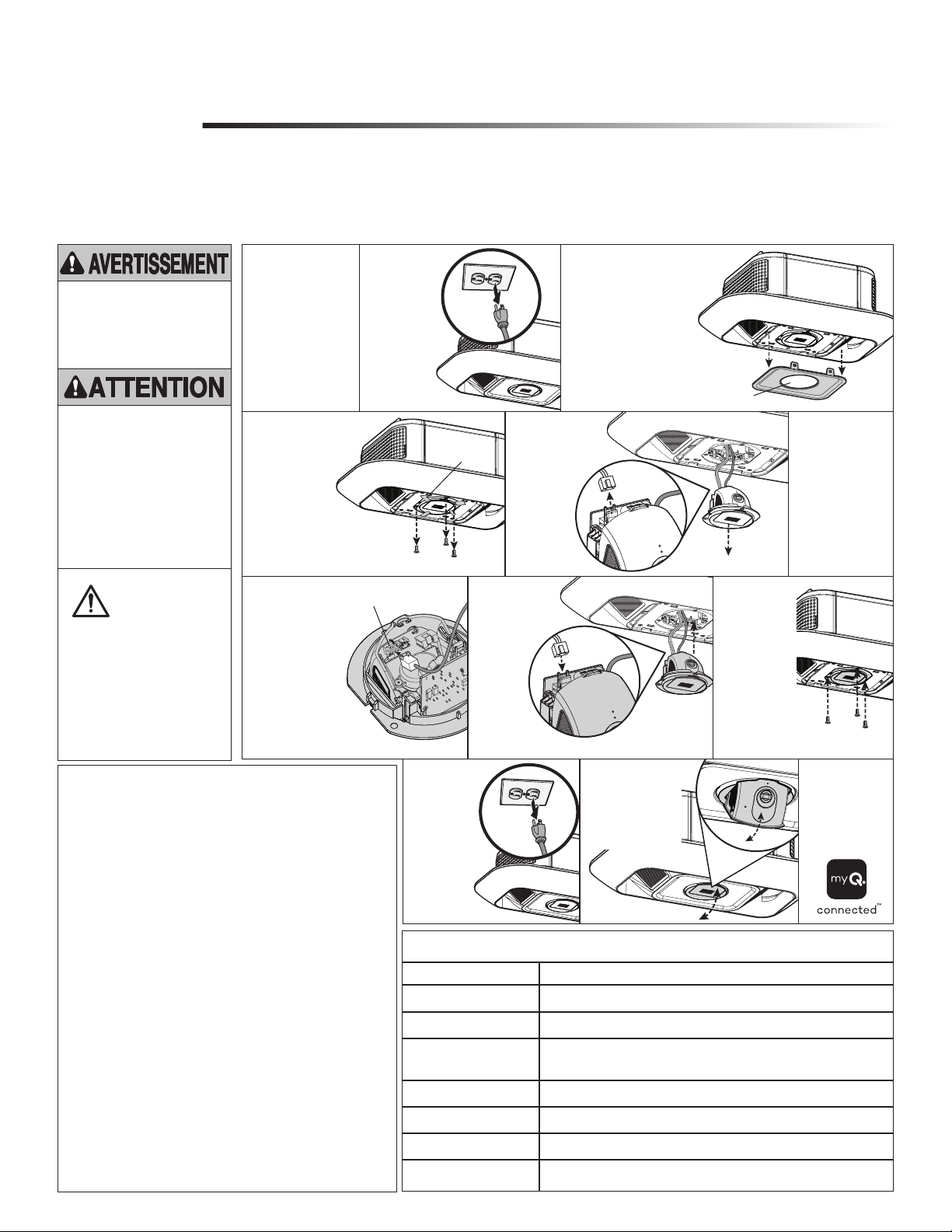
Pour prévenir les dommages à la
caméra, pousser la lentille de la
caméra en position fermée pendant
le remplacement et tenir la caméra
en place pendant le retrait du
matériel de fixation. NE PAS toucher
à la carte logique de la caméra
pendant l’installation.
Porter TOUJOURS des gants de
protection et des lunettes de sécurité
lors du remplacement de la batterie
ou d’une intervention à proximité du
compartiment de la batterie.
Introduction
Installation
REMPLACEMENT DE TROUSSE DE SERVICE DE CAMÉRA
Modèle 041-0347-000
Votre caméra est accessible du côté inférieur de l’ouvre-porte. Après
avoir installé la nouvelle caméra, servez-vous de l’appli myQ® pour
connecter la caméra à votre compte myQ®.
Pour éviter des BLESSURES
GRAVES, VOIRE MORTELLES:
• Débrancher TOUTE alimentation
électrique et la batterie AVANT
d’effectuer TOUT entretien ou
TOUTE intervention.
Témoins à DEL d’état de la caméra
CE QUE VOUS VOYEZ CE QUE ÇA SIGNIFIE
Blanche allumée en continu La caméra a été mise sous tension.
Clignotante bleue Prête à être configurée dans l’appli myQ
®
.
Bleue allumée en continu Connectée à votre appareil mobile Vous n’êtes pas encore connecté à Internet.
Si cette situation persiste après la configuration, vérifier le routeur du domicile
et Internet. Connexion en cours au Wi-Fi
®
et à l’appli myQ
®
.
Clignotante bleue et verte Connexion en cours au Wi- Fi et à l’appli myQ
®
.
Verte allumée en continu Connectée à l’appli myQ
®
.
Clignotante mauve Réception de mises à jour matérielles.
Rouge continu Erreur d’état thermique de la caméra quand celle-ci atteint une température de
grande chaleur de 60°C et refroidit.
Outils:
• Tournevis à tête cruciforme
• Tournevis à tête plate
• Échelle
• Ruban-cache (option)
Quincaillerie:
• Qté de vis 3
• Badge décoratif
• Caméra
AVERTISSEMENT : Ce dispositif est conforme à la de la partie15 du
règlement de la FCC et de l’exemption de licence RSS d’Innovation,
Sciences et Développement économique Canada. L’utilisation est assujettie
aux deux conditions suivantes : (1) ce dispositif ne peut causer de
brouillage nuisible, et (2) ce dispositif doit accepter tout brouillage reçu, y
compris tout brouillage pouvant causer un fonctionnement indésirable.
Tout changement ou modification non expressément approuvés par
la partie responsable de la conformité pourrait annuler l’autorité de
l’utilisateur d’utiliser l’équipement.
Cet appareil doit être installé de manière à laisser une distance d’au moins
20 cm (8 po) entre celui-ci et l’utilisateur ou toute personne.
Cet appareil a été testé et déclaré conforme aux limites d’un dispositif
numérique de Classe B, conformément à la partie 15 du règlement de
la FCC et de la norme NMB d’Innovation, Sciences et Développement
économique Canada. Ces limites ont pour but de fournir une protection
raisonnable contre le brouillage nuisible dans une installation résidentielle.
Cet équipement génère, utilise et peut émettre des fréquences radio et, s’il
n’est pas installé et utilisé conformément aux instructions, peut causer un
brouillage nuisible aux communications radio.
Cependant, rien ne garantit l’absence de brouillage dans une installation
particulière. Si cet équipement cause un brouillage nuisible à la réception
radio ou télévisée, ce qui peut être déterminé en éteignant et en rallumant
l’équipement, l’utilisateur est invité à tenter de corriger le brouillage en
prenant l’une des mesures suivantes :
• Réorienter ou relocaliser l’antenne de réception.
• Augmenter la distance entre l’équipement et le récepteur.
• Connecter l’équipement dans une prise de courant sur un circuit différent
de celui auquel le récepteur est branché.
• Pour obtenir de l’aide, consulter le détaillant ou un technicien radio
chevronné.
Les dispositifs fonctionnant dans la bande 5150-5250 MHz sont réservés
uniquement pour une utilisation à l’intérieur afin de réduire les risques de
brouillage préjudiciable aux systèmes de satellites mobiles utilisant les
mêmes canaux.
AVERTISSEMENT:
Ce produit peut
vous exposer à
des produits chimiques
comme le plomb, reconnu
par l’État de la Californie
comme cause de cancers,
d’anomalies congénitales
et d’autres problèmes liés
à la reproduction. Pour
plus d’informations, visitez
www.P65Warnings.ca.gov
11.
Localisez l’encoche
du dispositif
d’ouverture de
la caméra et
tirez vers le bas.
12.
Suivre les
instructions de
l’appli myQ
®
pour
ajouter la nouvelle
caméra à votre
compte myQ
®
.
10.
Fixez à nouveau
le nouveau
badge.
Rebranchez
l’alimentation et
la batterie, le cas
échéant.
3.
À l’aide d’un tournevis à
tête plate, retirez le badge
situé au bas de l’ouvre-
porte.
Le badge est maintenu
par quatre clips, retirez-le
en tirant dessus.
Badge
9.
Alignez les trous
de vis et placez
la caméra dans
l’ouvre-porte
de garage.
Fixez les
trois vis à l’aide
d’un tournevis
cruciforme.
2.
Débranchez
l’alimentation de
l’ouvre-porte de
garage et retirez
la batterie de
secours, le cas
échéant.
1.
Utilisez l’application
myQ pour supprimer
l’ouvre-porte de garage
du compte myQ avant
de l’ajouter à nouveau
ainsi que la caméra au
compte myQ.
6.
Ouvrez la caméra
et retirez le
harnais de fils à
trois broches qui
comporte les fils
noir, vert et blanc.
Faites tourner le
clip du connecteur
vers l’arrière
avant de retirer le
harnais de câbles.
Clip du connecteur
7.
Ouvrez la nouvelle
caméra et placez le
harnais de câbles
à trois broches qui
comporte les fils
noir, vert et blanc.
Remettez le clip
du connecteur
en place après la
reconnexion.
Fermez la caméra.
5.
Retirez le harnais de
fils à deux broches
qui comporte les
fils noir
et blanc.
4.
Dévissez lentement
la caméra du boîtier
de l’ouvre-porte
en retirant les
trois vis à l’aide
d’un tournevis
cruciforme.
CONSEIL: Utilisez du
ruban de masquage pour
maintenir la caméra en
place pendant que vous
retirez les vis.
Ruban de
masquage
8.
Branchez le harnais
de fils à deux
broches qui
comporte les
fils noir
et blanc

Wi-Fi
®
is a registered trademark of Wi-Fi Alliance.
Wi-Fi
®
es una marca comercial registrada de Wi-Fi Alliance.
Wi-Fi
®
est une marque déposée de Wi-Fi Alliance
© 2022, Chamberlain Group, LLC.
All Rights Reserved.
Todos los derechos reservados.
Tous droits réservés.
114-5812-000