Loading ...
Loading ...
Loading ...
64
Multi V Ducted Indoor Units
Due to our policy of continuous product innovation, some specifications may change without notification.
©LG Electronics U.S.A., Inc., Englewood Cliffs, NJ. All rights reserved. “LG” is a registered trademark of LG Corp.
WIRING
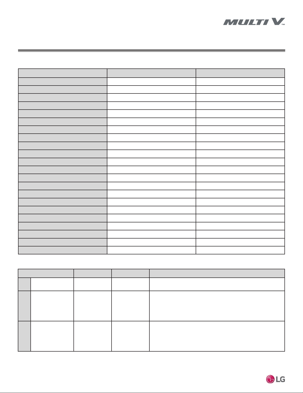
Table 31: Low-Static Ducted L2/L3 Chassis Wiring Diagram
Low-Static Ducted L2/L3 Chassis
CONNECTOR PURPOSE FUNCTION
CN-POWER
AC Power supply AC Power line
CN-MOTOR1
Fan motor output Motor output of BLDC
CN-MOTOR2
Fan motor output Motor output of BLDC
CN-DAMPER
N / A N / A
CN-ZONE
Zone controller Zone controller connection
CN-EXT
External on / off controller External on / off Controller connection
CN-EEV
EEV Output EEV control output
CN-OPTION
Optional PCB EPROM Option PCB connection
CN-DISPLAY
Display Display of indoor status
CN-PTC
Auxiliary heater Connection for Auxiliary Heater
CN-CC
Dry contact Dry Contact connection
CN-AIRC
N / A N / A
CN-LEAK
Leak detector Leak detector connection
CN-WF
N / A N / A
CN-HUMID
N / A N / A
CN-FLOAT
Float switch input Float switch sensing
CN-PIPE/OUT
Discharge pipe sensor Pipe out thermistor
CN-PIPE/IN
Suction pipe sensor Pipe in thermistor
CN-ROOM
Room sensor Room air thermistor
CN-REMO
Wired remote controller Wired remote control connection
CN-D/PUMP
Drain pump output AC output for drain pump
CN-485
Communication Connection between indoor and outdoor units
Table 32: L2, L3 Unit DIP Switch Settings.
*For Gen 4 Multi V ducted indoor units, DIP switches 1, 2, 6 through 8 must be set to OFF. These DIP switches are used for
other models.
**To enable Generation 4 features, outdoor unit DIP Switch No. 3 must be set to ON. Please refer to the Multi V IV, Multi V Wa-
ter IV, Multi V S Engineering Manual for additional information.
DIP Switch Setting Off On Remarks
SW3
GROUP CONTROL Master Slave
Group control setting using 7-Day Programmable Controller; selects Master /
Slave on each indoor unit
SW4
DRY CONTACT
MODE
Variable Auto
Sets operation mode for optional Dry Contact accessory
1. Variable: Auto or Manual Mode can be set through 7-Day Programmable
Controller or Wireless Remote Controller (factory default setting is Auto if
there is no setting)
2. Auto: For Dry Contact, it is always Auto mode
SW5
CONTINUOUS FAN Off On
Selects continuous fan for ducted indoor units.
1. On: Indoor unit fan will always operate at a set fan speed, except when
the system is off, or the outdoor unit is in defrost mode (when the oudoor unit
is in defrost mode, the fan will operate at super low fan speed)
2. Off: Indoor unit fan speed can be changed by on / off
Loading ...
Loading ...
Loading ...