Loading ...
Loading ...
Loading ...
12
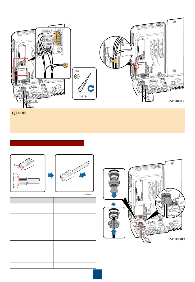
5. Bind the communications cable.
4. Install the terminal base on the terminal
block, and connect the shield layer to the
ground point.
• When connecting the shielded cable, choose whether to crimp the OT terminal based on site
requirements.
• Tie the communication cables with the cables on internal side of the maintenance compartment.
6. Tighten the thread-lock sealing nut and seal the cable gland.
1. Prepare an RJ45 connector. 2. Route the cable through the cable gland.
RJ45 Network Port Connection
No.
Color
Pin Definition
1
White
-and-
orange
RS485A, RS485
differential signal+
2
Orange
RS485B, RS485
differential signal
–
3
White
-and-green
N/A
4
Blue
RS485A, RS485
differential signal+
5
White
-and-blue
RS485B, RS485
differential signal
–
6
Green
N/A
7
White
-and-
brown
N/A
8
Brown
N/A
Loading ...
Loading ...
Loading ...