Loading ...
Loading ...
Loading ...
STIEBEL ELTRON
9
Installation Instruction for the qualied installer
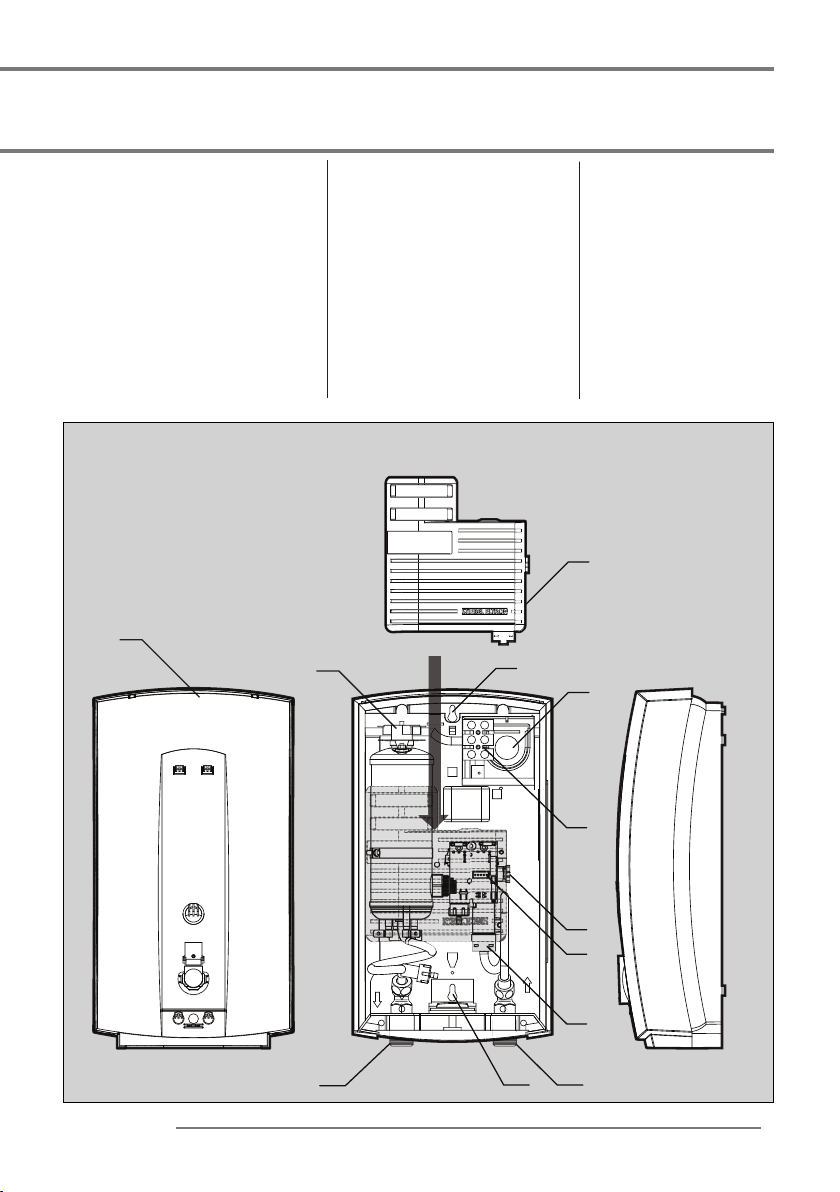
Description of the unit (Internal)
1
6
13
5
2 10
11
7
8
9
12
14
Fig. 2
Description of the unit
(internal)
1. Upper mounting hole
2. Lower mounting hole
3.
Depth for mounting screw
(Fig. 6 No.3)
4. Distance of the connection
cable (Fig. 5 No.4)
5. Thermostat
6. Cable entry with seal
7. Electrical connection
8. Plug connecting the circuit
board to the cover
9. Reed switch
10. Cold water connection
11. Hot water connection
12. Flow Limiter
13. Circuit board cover
14. Cover
Loading ...
Loading ...
Loading ...