Loading ...
Loading ...
Loading ...
23
OPERATIONS MANUAL
WORKTOPS/UNDERCOUNTERS & SANDWICH UNITS
Check that both plates are secure and that the casters turn
and swivel freely. Carefully lift the cabinet upright and double
check that the caster support plates are secure and the cabinet
is stable. Wait at least 3 hours before turning the refrigeration
system back on, and at least another 30 minutes for the cabinet
to come down to temperature and stabilize, before reloading
with product.
INSTALLING ELECTRIC CONDENSATE HEATER
The electric condensate heater has a thermal limit switch and
power cord attached. To install the heater, remove the screws
securing the back cover to the cabinet (see Figure 19) and set
the cover aside. Place the vaporizer heater in the drain pan as
shown and carefully position the end of the plastic drain tube in
the pan. Make sure the tubing is not kinked and the end is locat-
ed securely in the pan, so it does not touch the heating element.
Plug the power cord from the heater into the receptacle labeled
“vaporizer” on the lower back wall of the cabinet. Secure any
excess power cord with a wire tie, so it does not fall into the pan
or under the cabinet. Reattach the cover to the back of the
cabinet.
IMPORTANT NOTE: Always wear proper work gloves and
use appropriate safety equipment. You may CAREFULLY
lay the cabinet on it’s back, but only FOR A BRIEF
PERIOD OF TIME. Caution must be taken to ensure you
DO NOT DAMAGE the louvered back panel, refrigeration
system components, or copper tubing located behind the
panel. The cabinet must be properly blocked, to allow
room to get your hands in to lift without damaging the
cabinet or crushing the vents on the back panel. DO NOT
PLUG-IN OR OPERATE THE REFRIGERATION SYSTEM
FOR AT LEAST THREE (3) HOURS AFTER THE UNIT HAS
BEEN RETURNING IT TO AN UPRIGHT POSITION, AS
THIS CAN DAMAGE THE COMPRESSOR.
To install caster support plate assemblies, you will need a 3/4”
open end wrench (or a large adjustable wrench), a drill with a
1/8” bit and a Phillips bit (or a Phillips-Head screwdriver) plus
work gloves. A 1/2-13 thread tap is also recommended, to repair
any damage to the threaded inserts in the cabinet. Unload all
product and carefully lay the cabinet on its back. Remove the old
stem casters by unscrewing them from the cabinet. If a caster or
threaded insert has been stripped or cross-threaded, it may be
necessary to use a wrench to loosen the caster.
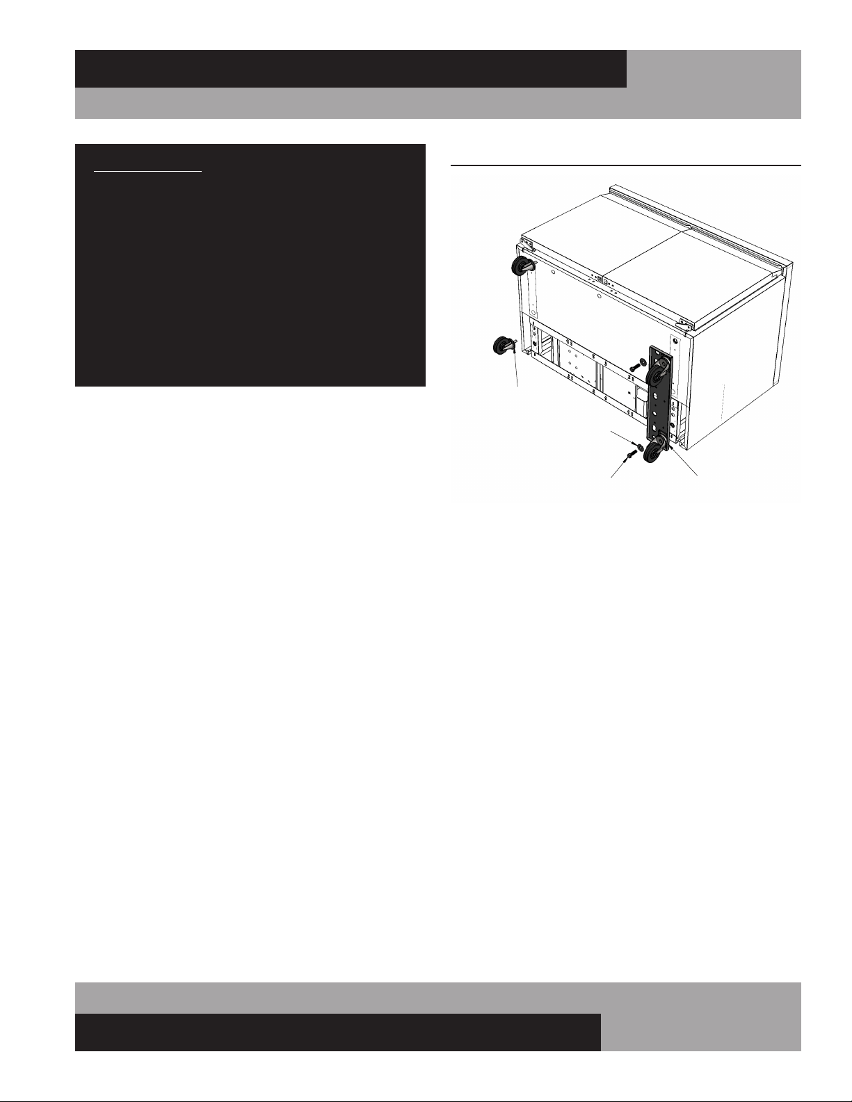
Hold one of the support plate assemblies under the cabinet as
shown (see Figure 18). Position it so the slotted holes at the end
of the plate line up with the threaded inserts in the bottom of the
cabinet (where the stem casters were attached). Attach the plate
assembly to the cabinet by putting a 1/2” x 1-3/4” long bolts and
flat washer through the slot in the support plate and screwing
into each of the threaded inserts in the bottom of the cabinet.
Snug the bolts down, but do not tighten them completely. If
one of the threaded inserts is stripped or damaged, a thread tap
should be used to clean the threads.
Using the small holes in the plate as a template, drill 1/8 pilot
holes in the bottom of the cabinet. (Note: drill only until you
penetrate the metal bottom of the cabinet. Do not continue
to drill into the insulation, or you may damage the cabinet.)
Secure the caster support plate assembly to the cabinet with a
sheet metal screw in each of the drilled holes. Tighten the 1/2”
bolts. Repeat these steps to attach the other plate assembly to
the opposite end of the cabinet.
FIGURE 18: Caster Support Plates
SUPPORT ASSEMBLY
WITH PLATE CASTER
1/2-13 BOLT
(2 PER PLATE)
FLAT WASHER
(2 PER PLATE)
REMOVE OLD
STEM CASTERS
BOTTOM
OF CABINET
Loading ...
Loading ...
Loading ...