Loading ...
Loading ...
Loading ...
NOTE
If there is a stereo jack connected to +12V TRIGGER IN, the C 368 cannot be
powered ON/OFF using the front panel Standby button or SR 9’s ON/OFF
buttons. The stereo jack has to be unplugged to resume normal powering
up of the unit via front panel Standby button or SR 9’s ON/OFF buttons.
6 BRIDGE MODE
The C 368 amplier can be congured to be MONO (Bridge Mode),
more than doubling its output power. This way, the C 368 can be used
as part of a high power stereo or home-theatre system, by connecting
additional power ampliers.
• In BRIDGED MODE (switch at ON (MONO) setting), the C 368 will
produce approximately 300W into an 8 ohm loudspeaker. In this
mode, the amplier sections will react as though the speaker
impedance has been halved. Low impedance speakers (under 8
ohms) are not recommended when using Bridge Mode as these
may cause the amplier’s thermal cut-out to operate if played at
high levels.
• Set the BRIDGE MODE switch to the “ON (MONO)” position and
connect the speaker to the terminals marked “L +” and “R-” ensuring
that the “L+” is connected to the “+” terminal of your speaker and
the “R-” is connected to the speaker’s “ - ” terminal.
• Connect the source to the Left input sockets only. Do not connect
anything to the Right Input socket when Bridge Mode is selected.
7 SPEAKERS
• The C 368 has two sets of SPEAKER connections which are identical
in function (parallel connection).
• Connect C 368’s Right speaker terminals marked “R +” and “R-” to
the corresponding “+” and “-“ terminals of your designated right
speaker. Repeat the same for C 368’s Left speaker terminals and
corresponding left speaker.
• Double check the speaker connections before powering up the
C 368.
IMPORTANT NOTES
• The blue terminals must never be connected to ground (earth).
• Never connect the blue terminals together or to any common ground
device.
• Do not connect the output of this amplier to any headphone adapter,
speaker switch or any device that uses common ground for left and
right channels.
NOTES
• Use 16 gauge (American Wire Gauge or AWG) or lower stranded wire.
Connections to the C 368 can be made with banana-type plugs.
• Bare wire or pins can also be used by loosening the terminal’s plastic
nut, making a clean, neat connection and re-tightening. To minimize
the danger of a short circuit, ensure that only 1/2-inch of exposed wire
or pin is used to connect and no loose strands of speaker wire.
8 POWER
• Supplies the AC mains power to the C 368.
• When the POWER switch is set to ON position, the C 368 goes to
standby mode as shown by the amber status condition of the front
panel Power indicator.
• Press the front panel Standby button or SR 9’s remote control’s [ON]
button to switch ON the C 368 from standby mode.
• If you do not intend to use the C 368 for long periods of time (such
as when on vacation), switch o the POWER switch.
• With POWER switched o, neither the front panel Standby button
nor SR 9 remote control’s [ON] button can activate the C 368.
9 FUSE HOLDER
• Only qualied NAD service technicians can have access to this fuse
holder. Opening this fuse holder may cause damage thus voiding
the warranty of your C 368.
10 AC MAINS INPUT
• The C 368 comes supplied with two separate mains power cords.
Select the mains power cord appropriate for your region.
• Before connecting the plug to the mains power source, ensure that
it is rmly connected to the C 368’s AC Mains input socket.
• Always disconnect the mains power plug from the mains power
source before disconnecting the cable from the C 368’s AC Mains
input socket.
11 SERVICE
• Use for servicing purposes only. Not for consumer use.
12 BLUETOOTH ANTENNA TERMINAL
• Install supplied Bluetooth antenna to this Bluetooth antenna
terminal.
13 GROUND TERMINAL
• Ensure that the C 368 is plugged-in to a grounded AC wall outlet.
• If necessary, use this ground terminal to connect to ground a
phono or turntable source for PHONO input.
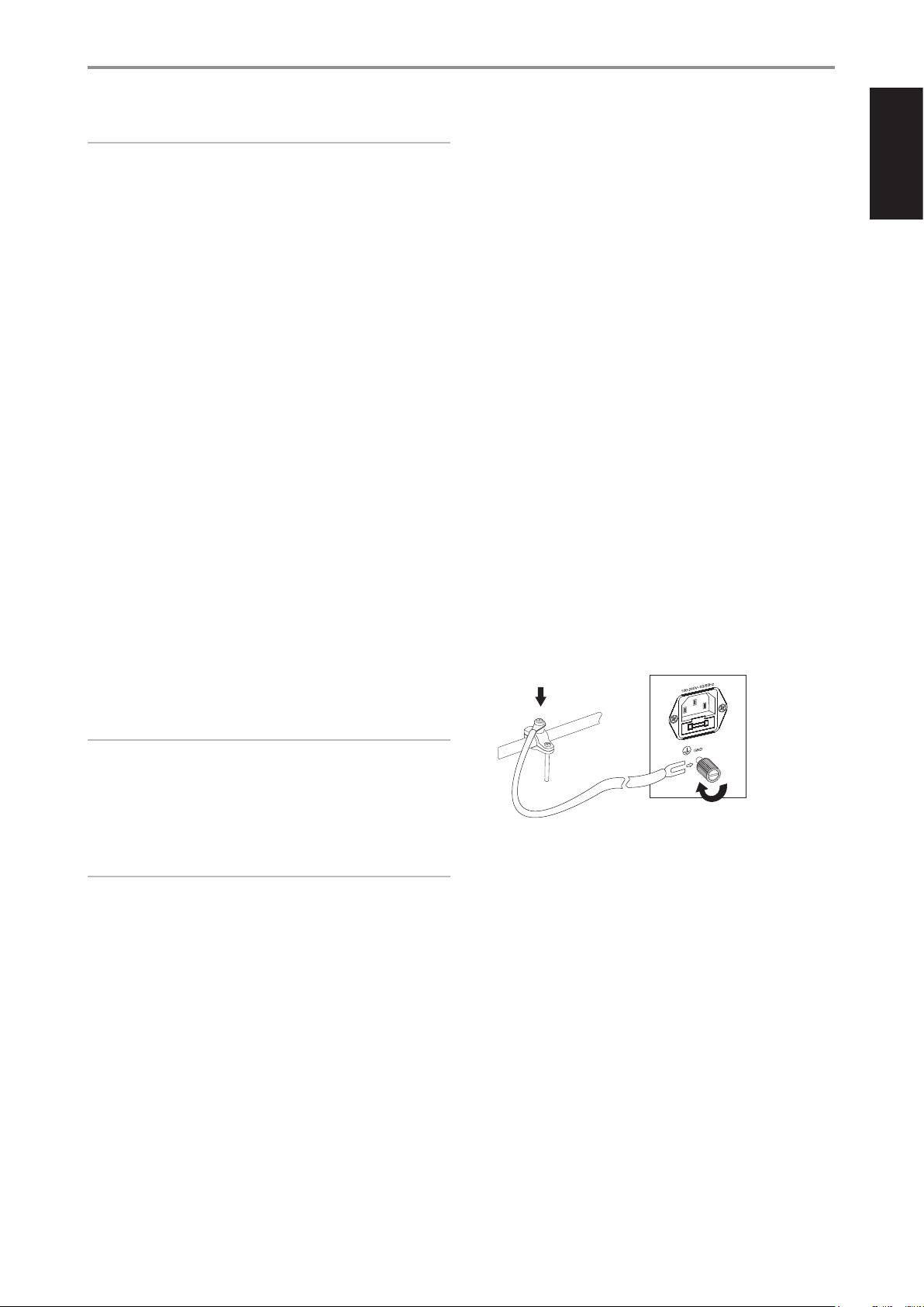
• If a separate earth ground is necessary, use this terminal to ground
your C 368. The C 368 can be connected to ground by connecting
a ground lead wire or similar to this terminal. After insertion, tighten
the terminal to secure the lead.
EXAMPLE ILLUSTRATION OF GROUNDING THE C 368 VIA THE
REAR PANEL GROUND TERMINAL
14 RS 232
NAD is a certied partner of AMX and Crestron and fully supports
these external devices. Check out the NAD website for information
about AMX and Crestron compatibility with NAD. See your NAD audio
specialist for more information.
• Connect this interface using RS-232 serial cable (not supplied) to
any Windows compatible PC to allow remote control of the C 368
via compatible external controllers.
• Refer to the NAD website for information about RS232 Protocol
documents and PC interface program.
IDENTIFICATION OF CONTROLS
REAR PANEL
7
ENGLISHFRANÇAISESPAÑOLITALIANODEUTSCHNEDERLANDSSVENSKAРУССКИЙ
Loading ...
Loading ...
Loading ...