Loading ...
Loading ...
Loading ...
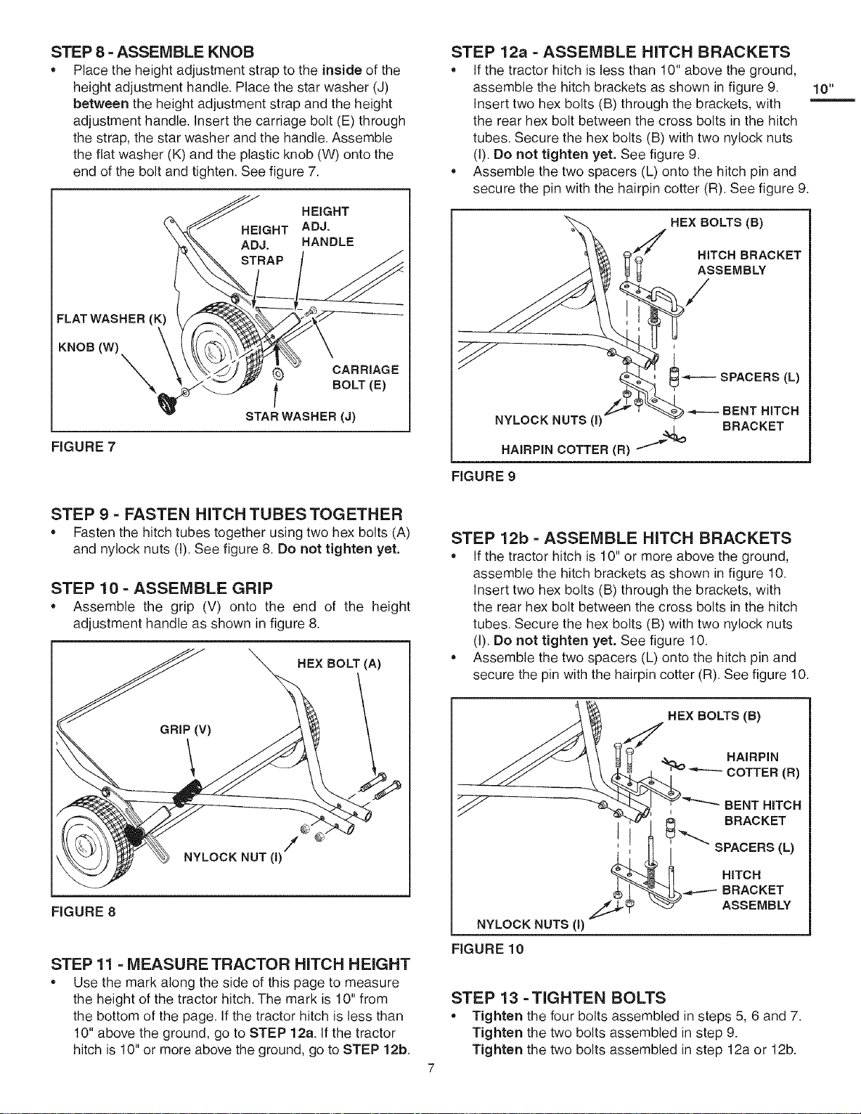
STEP 8 - ASSEMBLE KNOB
• Place the height adjustment strap to the inside of the
height adjustment handle. Place the star washer (J)
between the height adjustment strap and the height
adjustment handle. Insert the carriage bolt (E) through
the strap, the star washer and the handle. Assemble
the flat washer (K) and the plastic knob (W) onto the
end of the bolt and tighten. See figure 7.
HEIGHT
HEIGHT ADJ.
ADJ. HANDLE
FLAT WASHER (K)
KNOB (W)
CARRIAGE
i BOLT (E)
STAB WASHER (J)
FIGURE 7
STEP 9 - FASTEN HITCH TUBES TOGETHER
• Fasten the hitch tubes together using two hex bolts (A)
and nylock nuts (I). See figure 8. Do not tighten yet,
STEP 10 - ASSEMBLE GRIP
• Assemble the grip (V) onto the end of the height
adjustment handle as shown in figure 8.
HEX BOLT (A)
NYLOCK NUT(1)
FIGURE 8
STEP 11 -MEASURE TRACTOR HITCH HEIGHT
• Use the mark along the side of this page to measure
the height of the tractor hitch. The mark is 10" from
the bottom of the page. If the tractor hitch is less than
10" above the ground, go to STEP 12a. If the tractor
hitch is 10" or more above the ground, go to STEP 12b.
STEP 12a- ASSEMBLE HITCH BRACKETS
• If the tractor hitch is less than 10" above the ground,
assemble the hitch brackets as shown in figure 9.
Insert two hex bolts (B) through the brackets, with
the rear hex bolt between the cross bolts in the hitch
tubes. Secure the hex bolts (B) with two nylock nuts
(I). Do not tighten yet. See figure 9.
• Assemble the two spacers (L) onto the hitch pin and
secure the pin with the hairpin cotter (R). See figure 9.
10"
NYLOCK NUTS (I)'_
HEX BOLTS (B)
_ A_STCH2BtAC KET
/
s;2c;2;'22
BRACKET
HAIRPIN COTTER (B) /"_,o
FIGURE 9
STEP 12b - ASSEMBLE HITCH BRACKETS
• If the tractor hitch is 10" or more above the ground,
assemble the hitch brackets as shown in figure 10.
Insert two hex bolts (B) through the brackets, with
the rear hex bolt between the cross bolts in the hitch
tubes. Secure the hex bolts (B) with two nylock nuts
(I). Do not tighten yet. See figure 10.
• Assemble the two spacers (L) onto the hitch pin and
secure the pin with the hairpin cotter (R). See figure 10.
HEX BOLTS (B)
_ HAiRPiN
COTTER (R)
BENT HITCH
-_.
I
I _. BRACKET
I SPACERS (L)
HITCH
BRACKET
ASSEMBLY
NYLOCK NUTS (I)
FIGURE 10
STEP 13 -TIGHTEN BOLTS
• Tighten the four bolts assembled in steps 5, 6 and 7.
Tighten the two bolts assembled in step 9.
Tighten the two bolts assembled in step 12a or 12b.
Loading ...
Loading ...
Loading ...