Loading ...
Loading ...
Loading ...
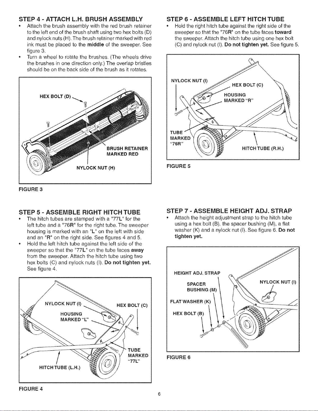
STEP 4 - ATTACH L.H. BRUSH ASSEMBLY
• Attach the brush assembly with the red brush retainer
to the left end of the brush shaft using two hex bolts (D)
and nylock nuts (H). The brush retainer marked with red
ink must be placed to the middle of the sweeper• See
figure 3.
Turn a wheel to rotate the brushes• (The wheels drive
the brushes in one direction only•) The overlap bristles
should be on the back side of the brush as it rotates•
BRUSH RETAINER
MARKED RED
NYLOCK NUT (H)
STEP 6 =ASSEMBLE LEFT HITCH TUBE
Hold the right hitch tube against the right side of the
sweeper so that the "76R" on the tube faces toward
the sweeper. Attach the hitch tube using one hex bolt
(C) and nylock nut (I). Do not tighten yet, See figure 5.
NYLOCK NUT(I)
MARKED \
"76R"
HITCHTUBE(R.H.)
FIGURE 5
FIGURE 3
STEP 5 - ASSEMBLE RIGHT HITCH TUBE
The hitch tubes are stamped with a "77L" for the
left tube and a "76R" for the right tube. The sweeper
housing is marked with an "L" on the left with side
and an "R" on the right side. See figures 4 and 5.
Hold the left hitch tube against the left side of the
sweeper so that the "77L" on the tube faces away
from the sweeper. Attach the hitch tube using two
hex bolts (C) and nylock nuts (I). Do not tighten yet,
See figure 4.
HEX BOLT (C)
• TUBE
MARKED
"771='
HITCH TUBE (L.H.)
STEP 7 - ASSEMBLE HEIGHT ADJ. STRAP
Attach the height adjustment strap to the hitch tube
using a hex bolt (B), the spacer bushing (M), a flat
washer (K) and a nylock nut (I). See figure 6. Do not
tighten yet.
HEIGHT ADJ. STRAP
SPACER
BUSHING (M)
FLAT WASHER (K)
HEX BOLT (B)
FIGURE 6
FIGURE 4
6
Loading ...
Loading ...
Loading ...