-lectric
Range
Installation
manual
ENGLISH
Thank
you
for
purchasing-this
Samsung
product.
To
receive
more
complete
service,
please
register
your
product-at
www.samsung.com/register
1-800-SAMSUNG(726-7864)
100%
Recycled
Paper
This
rnanual
is
rnace
with
100%
recycled
paper.
Installation-USA
DG68-00108E-01_EN.indd
1
2011-03-18
00
4:06:26
before
you
_bedin
ABOUT
THIS
MANUAL
READ
THESE
INSTRUCTIONS
COMPLETELY
AND
CAREFULLY.
Important
note
to
the
installer
Read
all
instructions
contained
in
these
installation
instructions
before
installing
range.
Remove
all
packing
materials from
the
oven
compartments
before
connecting
the
electrical
supply
to
the
range.
Observe
all
governing
codes
and
ordinances.
Be
sure
to
leave
these
instructions
with
the
consumer.
Important
note
to
the
consumer
Keep
these
instructions
for
the
local
electrical
inspector’s
use.
As
when
using any
appliance
generating
heat,
there
are
certain
safety
precautions
you
should
follow.
Be
sure
your
range
is
installed
and
grounded
properly
by
a
qualified
installer
or
service
technician.
Make
sure
the
wall
coverings
around
the
range
can
withstand
the
heat
generated
by
the
range.
To
eliminate
the
need
to
reach
over
the
surface
elements,
cabinet
storage
space above
the
elements
should
be
avoided.
The
range
should
not
be
placed
on
a
base.
FOR
YOUR
SAFETY
WARNING
WARNING
If
the
information
in
this
manual
is
not
followed
exactly,
a
fire
or
electrical
shock
may
result
causing
property
damage,
personal
injury
or
death.
WARNING
WARNING
Before
beginning
the
installation,
switch
power
off
at
the
service
panel
and
lock
the
service
disconnecting
means
to
prevent
power
from
being
switched
on
accidentally.
When
the
service
disconnecting
means
cannot
be
locked,
securely
fasten
a
prominent
warning
device,
such
as
a
tag,
to
the
service
panel.
A
WARNING
This
appliance
must
be
properly
grounded.
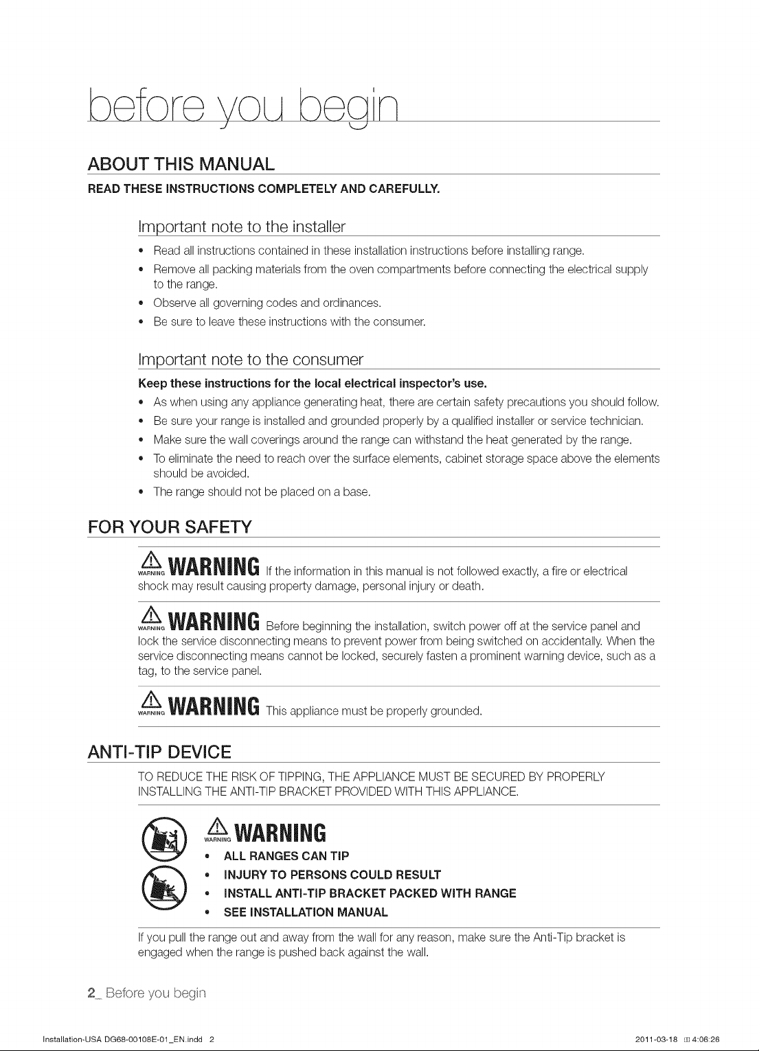
ANTI-TIP
DEVICE
TO
REDUCE
THE
RISK
OF
TIPPING,
THE
APPLIANCE
MUST
BE
SECURED
BY
PROPERLY
INSTALLING
THE
ANTI-TIP
BRACKET
PROVIDED
WITH
THIS
APPLIANCE.
(xs)
AS
WARNING
e
ALL
RANGES
CAN
TIP
e
INJURY
TO
PERSONS
COULD
RESULT
e
INSTALL
ANTI-TIP
BRACKET
PACKED
WITH
RANGE
e
SEE
INSTALLATION
MANUAL
If
you
pull
the
range
out
and
away
from
the
wall
for
any
reason,
make
sure
the
Anti-Tip
bracket
is
engaged
when
the
range
is
pushed
back
against
the
wall.
2_
Before
you
begin
Installation-USA
DG68-00108E-01_EN.indd
2
2011-03-18
00
4:06:26
REMOVE
PACKAGING
Remove
packaging
materials.
Failure
to
remove
packaging
materials
could
result
in
damage
to
the
appliance.
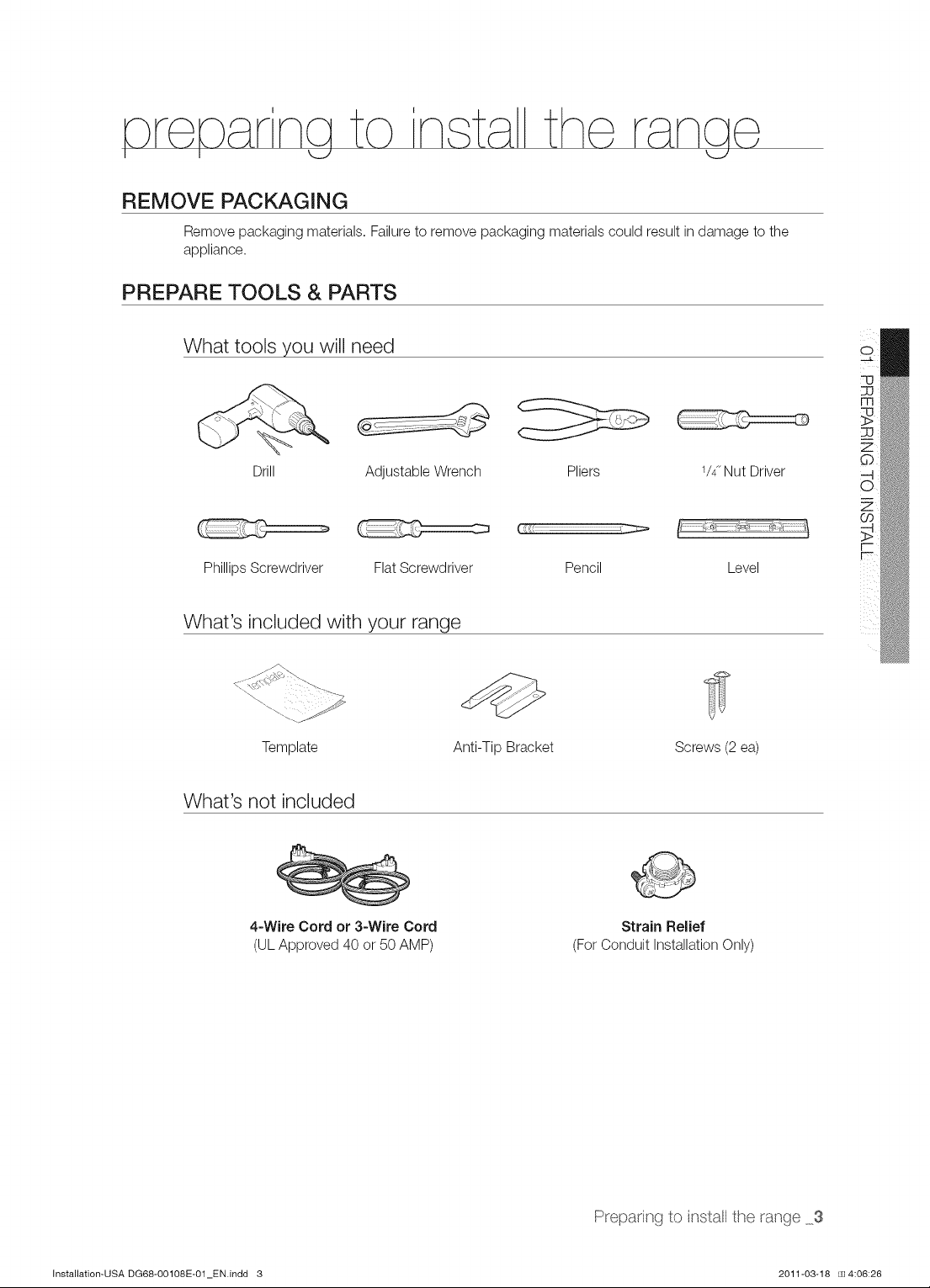
PREPARE
TOOLS
&
PARTS
What
tools
you
will
need
OQ
UD
we)
a
>
a
Zz
Qo
Pliers
1/4
Nut
Driver
—|
oO.
Zz
a
¢
——
a
=)
Phillips
Screwdriver
Flat
Screwdriver
Pencil
Level
|
What’s
included
with
your
range
Template
Anti-Tip
Bracket
Screws
(2
ea)
What's
not
included
4-Wire
Cord
or
3-Wire
Cord
Strain
Relief
(UL
Approved
40
or
50
AMP)
(For
Conduit
Installation
Only)
Preparing
to
install
the
range
_3
Installation-USA
DG68-00108E-01_EN.indd
3
2011-03-18
00
4:06:26
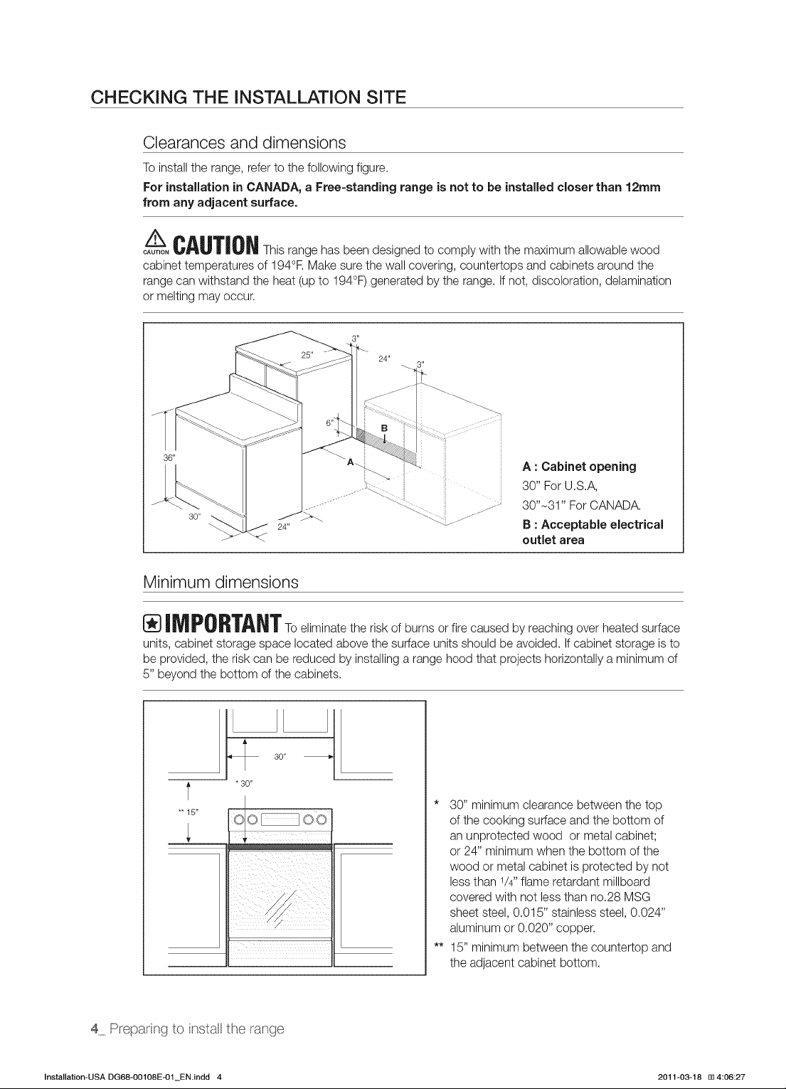
CHECKING
THE
INSTALLATION
SITE
Clearances
and
dimensions
To
install
the
range,
refer
to
the
following
figure.
For
installation
in
CANADA,
a
Free-standing
range
is
not
to
be
installed
closer
than
12mm
from
any
adjacent
surface.
A
CAUTION
This
range
has
been
designed
to
comply
with
the
maximum
allowable
wood
cabinet
temperatures
of
194°F.
Make
sure
the
wall
covering,
countertops
and
cabinets
around
the
range
can
withstand
the
heat
(up
to
194°F)
generated
by
the
range.
If
not,
discoloration,
delamination
or
melting
may
occur.
A:
Cabinet
opening
30”
For
U.S.A,
30"~31”
For
CANADA.
B
:
Acceptable
electrical
outlet
area
Minimum
dimensions
IM
PORTANT
To
eliminate
the
risk
of
burns
or
fire
caused
by
reaching
over
heated
surface
units,
cabinet
storage
space
located
above
the
surface
units
should
be
avoided.
If
cabinet
storage
is
to
be
provided,
the
risk
can
be
reduced
by
installing
a
range
hood
that
projects
horizontally
a
minimum
of
5”
beyond
the
bottom
of
the
cabinets.
30”
——+
f
30
ogg
*
30”
minimum
clearance
between
the
top
gone
joo
of
the
cooking
surface and
the
bottom
of
|
an
unprotected
wood
or
metal
cabinet;
——]
|
——___—
or
24”
minimum
when
the
bottom
of
the
wood
or
metal
cabinet
is
protected
by
not
less
than
1/4”
flame retardant millboard
Le
covered
with
not
less
than
no.28
MSG
i
sheet
steel,
0.015”
stainless
steel,
0.024”
“
aluminum
or
0.020”
copper.
**
15”
minimum
between
the
countertop
and
the
adjacent
cabinet
bottom.
4
Preparing
to
install
the
range
Installation-USA
DG68-00108E-01_EN.indd
4
2011-03-18
i
4:06:27
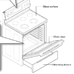
connecting
the
power
STEP
1.
MEETING
ELECTRICAL
CONNECTION
REQUIREMENTS
CAUTION
CAUTION
For
personal
safety,
do
not
use
an
extension
cord
with
this
appliance.
Remove
house
fuse
or
open
circuit
breaker
before
beginning
installation.
This
appliance
must
be
supplied
with
the
proper
voltage
and
frequency,
and
connected
to
an
individual
properly
grounded
branch
circuit,
protected
by
a
circuit
breaker
or
fuse
having
amperage
as
specified
on
the
rating
plate.
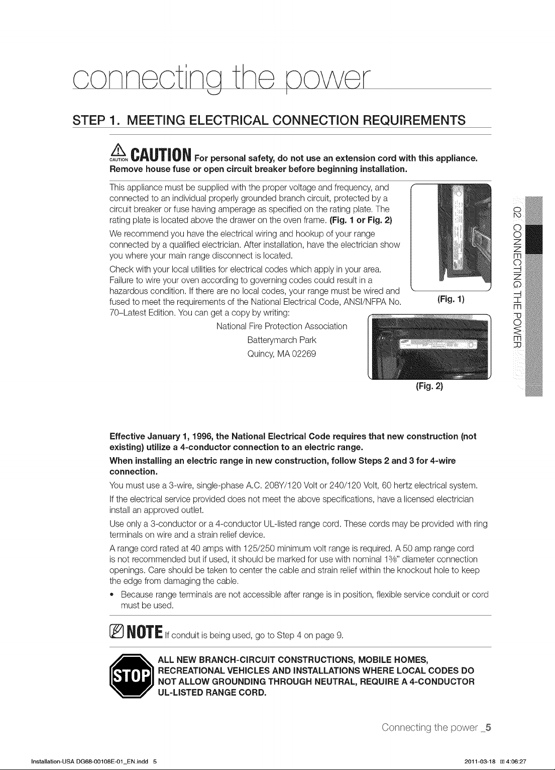
The
rating
plate
is
located
above
the
drawer
on
the
oven
frame.
(Fig.
1
or
Fig.
2)
We
recommend
you
have
the
electrical
wiring
and
hookup
of
your
range
connected
by
a
qualified
electrician.
After
installation,
nave
the
electrician
show
you
where
your
main
range
disconnect
is
located.
Check
with
your
local
utilities
for
electrical
codes
which
apply
in
your
area.
Failure
to
wire
your
oven
according
to
governing
codes
could
result
in
a
hazardous
condition.
If
there
are
no
local
codes,
your
range
must
be
wired
and
-
fused
to
meet
the
requirements
of
the
National
Electrical
Code,
ANSI/NFPA
No.
(Fig.
1)
70-Latest
Edition.
You
can
get
a
copy
by
writing:
National
Fire
Protection
Association
Batterymarch
Park
Quincy,
MA
02269
daMOd
SHL
ONILOANNOO
dO
(Fig.
2)
Effective
January
1,
1996,
the
National
Electrical
Code
requires
that
new
construction
(not
existing)
utilize
a
4-conductor
connection
to
an
electric
range.
When
installing
an
electric
range
in
new
construction,
follow
Steps
2
and
3
for
4-wire
connection.
You
must
use
a
3-wire,
single-phase
A.C.
208Y/120
Volt
or
240/120
Volt,
60
hertz
electrical
system.
If
the
electrical
service
provided
does
not
meet
the
above
specifications,
have
a
licensed
electrician
install
an
approved
outlet.
Use
only
a
3-conductor
or
a
4-conductor
UL-listed
range
cord.
These
cords
may
be
provided
with
ring
terminals
on
wire
and
a
strain
relief
device.
Arange
cord
rated
at
40
amps
with
125/250
minimum
volt
range
is
required.
A
50
amp
range
cord
is
not
recommended
but
if
used,
it
should
be
marked
for
use
with
nominal
136”
diameter
connection
openings.
Care should
be
taken
to
center
the
cable
and
strain
relief
within
the
knockout
hole
to
keep
the
edge
from
damaging
the
cable.
®
Because
range
terminals
are
not
accessible
after
range
is
in
position,
flexible
service
conduit
or
cord
must
be
used.
NOTE
If
conduit
is
being
used,
go
to
Step
4
on
page
9.
ALL
NEW
BRANCH-CIRCUIT
CONSTRUCTIONS,
MOBILE
HOMES,
RECREATIONAL
VEHICLES
AND
INSTALLATIONS
WHERE
LOCAL
CODES
DO
NOT
ALLOW
GROUNDING
THROUGH
NEUTRAL,
REQUIRE
A
4-CONDUCTOR
UL-LISTED
RANGE
CORD.
Connecting
the
power
5
Installation-USA
DG68-00108E-01_EN.indd
5
2011-03-18
i
4:06:27
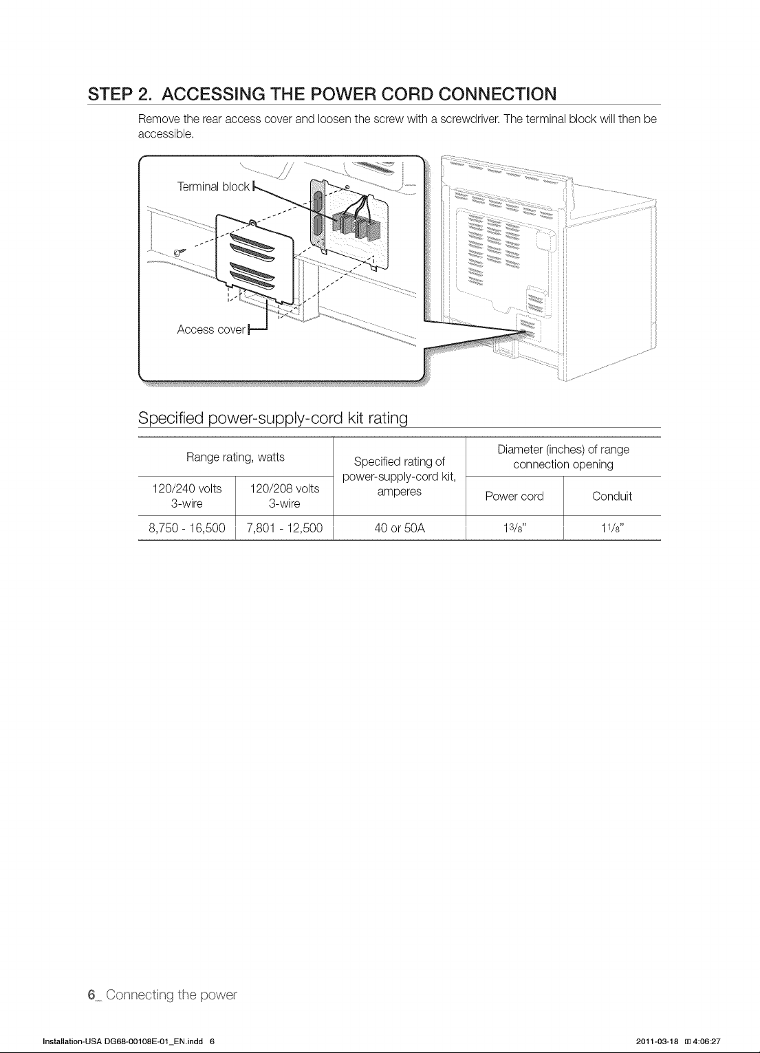
STEP
2.
ACCESSING
THE
POWER
CORD
CONNECTION
Remove
the
rear
access
cover
and
loosen
the
screw
with
a
screwdriver.
The
terminal
block
will
then
be
accessible.
la
Terminal
block
Access
cover
Specified
power-supply-cord
kit
rating
Range
rating,
watts
120/240
volts
120/208
volts
3-wire 3-wire
Specified
rating
of
power-supply-cord
kit,
amperes
Diameter
(inches)
of
range
connection
opening
Power
cord
Conduit
8,750
-
16,500
|
7,801
-
12,500
AO
or
50A
18/8”
11/3”
6
_
Connecting
the
power
Installation-USA
DG68-00108E-01_EN.indd
6
2011-03-18
i
4:06:27
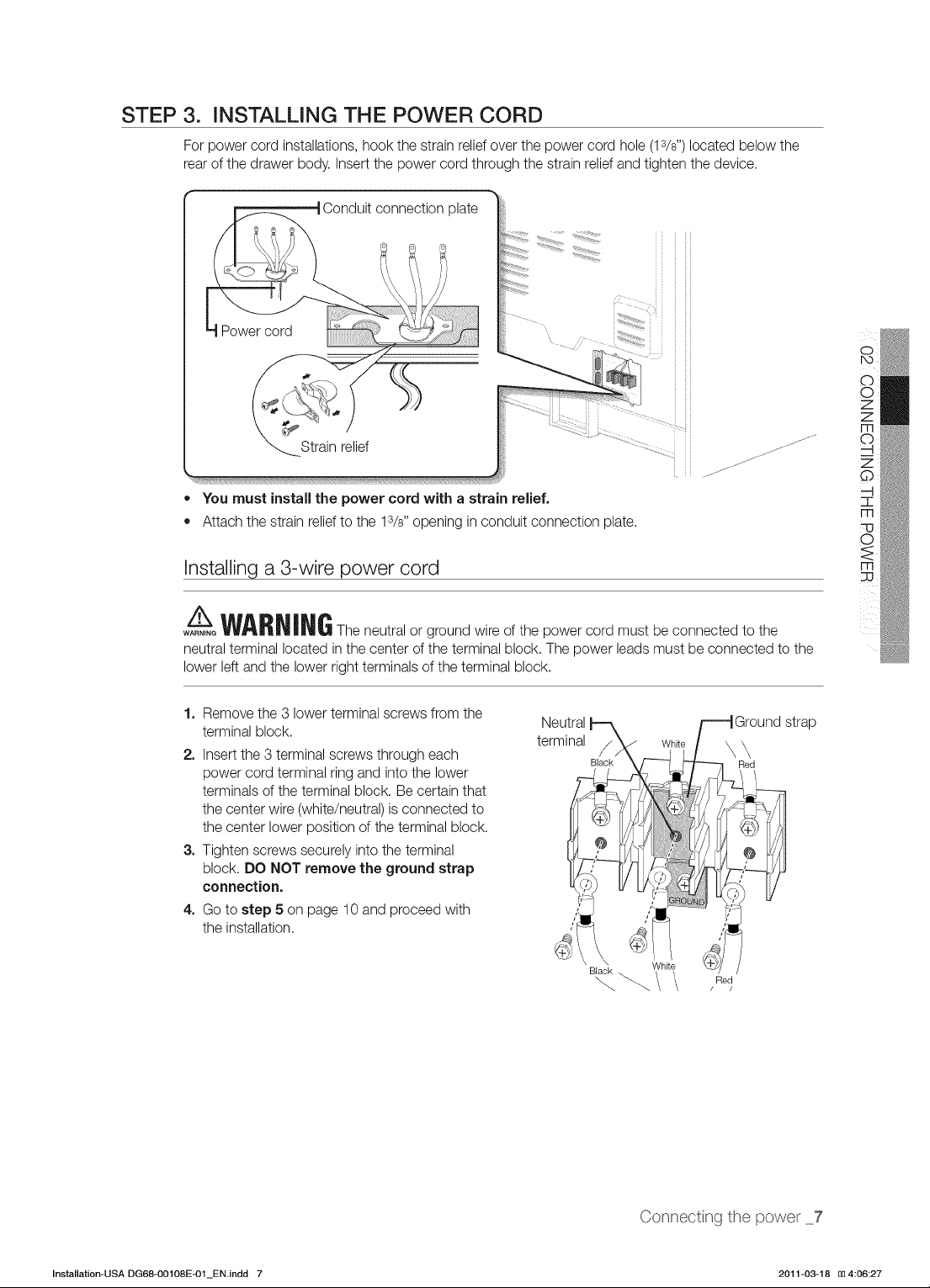
STEP
3.
INSTALLING
THE
POWER
CORD
For
power
cord
installations,
hook
the
strain
relief
over
the
power
cord
hole
(13/s”)
located
below
the
rear
of
the
drawer
body.
Insert
the
power
cord
through
the
strain
relief
and
tighten
the
device.
eneneed
SONCuit
connection
plate
Strain
relief
:
-
@
You
must
install
the
power
cord
with
a
strain
relief.
@
Attach
the
strain
relief
to
the
1/8”
opening
in
conduit
connection
plate.
daMOd
SHL
ONILOANNOO
dO
Installing
a
3-wire
power
cord
A
WARN
ING
The
neutral
or
ground
wire
of
the
power
cord
must
be
connected
to
the
neutral
terminal
located
in
the
center
of
the
terminal
block.
The
power
leads
must
be
connected
to
the
lower
left
and
the
lower
right
terminals
of
the
terminal
block.
1.
Remove
the
3
lower
terminal
screws
from
the
terminal
block.
terminal
White
2.
Insert
the
3
terminal
screws
through
each
/
\
\
power
cord
terminal
ring
and
into
the
lower
terminals
of
the
terminal
block.
Be
certain
that
cs
the
center
wire
(white/neutral)
is
connected
to
the
center
lower
position
of
the
terminal
block.
3.
Tighten
screws
securely
into
the
terminal
y
block.
DO
NOT
remove
the
ground
strap
f
connection.
4,
Go
to
step
5
on
page
10
and
proceed
with
ij
the
installation.
‘
Neutral
Ground
strap
Black
Connecting
the
power
_7
Installation-USA
DG68-00108E-01_EN.indd
7
2011-03-18
i
4:06:27
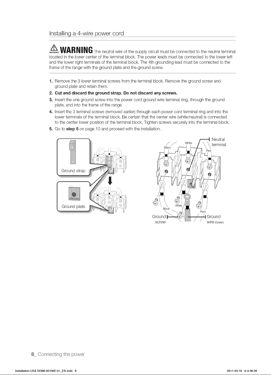
Installing
a
4-wire
power
cord
WARNING
WARNING
The
neutral
wire
of
the
supply
circuit
must
be
connected
to
the
neutral
terminal
located
in
the
lower
center
of
the
terminal
block.
The
power
leads
must
be
connected
to
the
lower
left
and
the
lower
right
terminals
of
the
terminal
block.
The
4th
grounding
lead
must
be
connected
to
the
frame
of
the
range
with
the
ground
plate
and
the
ground
screw.
1.
Remove
the
3
lower
terminal
screws
from
the
terminal
block.
Remove
the
ground screw
and
ground
plate
and
retain
them.
2.
Cut
and
discard
the
ground
strap.
Do
not
discard
any
screws.
3.
Insert
the
one
ground
screw
into
the
power
cord
ground
wire
terminal
ring,
through
the
ground
plate,
and
into
the
frame
of
the
range.
4,
Insert
the
3
terminal
screws
(removed
earlier)
through
each
power
cord
terminal
ring
and
into
the
lower
terminals
of
the
terminal
block.
Be
certain
that
the
center
wire
(white/neutral)
is
connected
to
the
center
lower
position
of
the
terminal
block.
Tighten
screws
securely
into
the
terminal
block.
5.
Go
to
step
5
on
page
10
and
proceed
with
the
installation.
Ground
strap
Ground
plate
wire
(Green)
8_
Connecting
the
power
Installation-USA
DG68-00108E-01_EN.indd
8
2011-03-18
i
4:06:28
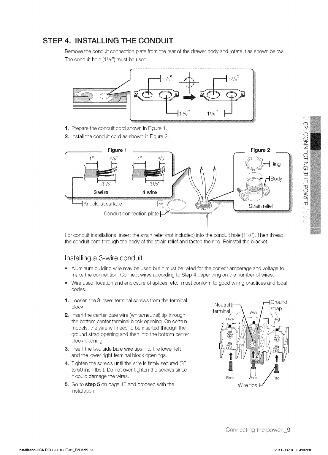
STEP
4.
INSTALLING
THE
CONDUIT
Remove
the
conduit
connection
plate
from
the
rear
of
the
drawer body
and
rotate
it
as
shown
below.
The
conduit
hole
(11/s”)
must
be
used.
1.
2.
For
conduit
installations,
insert
the
strain
relief
(not
included)
into
the
conduit
hole
(11/8”).
Then
thread
Prepare
the
conduit
cord
shown
in
Figure
1.
Install
the
conduit
cord
as
shown
in
Figure
2.
Figure
1
Figure
2
3/e
daMOd
SHL
ONILOANNOO
dO
Strain
relief
the
conduit
cord
through
the
body
of
the
strain
relief
and
fasten
the
ring.
Reinstall
the
bracket.
Installing
a
3-wire
conduit
.
Loosen
the
3
lower
terminal
screws
from
the
terminal
.
Insert
the
center
bare
wire
(white/neutral)
tio
through
.
Insert
the
two
side
bare
wire
tips
into
the
lower
left
.
lighten
the
screws
until
the
wire
is
firmly
secured
(35
Aluminum
building
wire
may
be
used
but
it
must
be
rated
for
the
correct
amperage
and
voltage
to
make
the
connection.
Connect
wires
according
to
Step
4
depending
on
the
number
of
wires.
Wire
used,
location
and
enclosure
of
splices,
etc.,
must
conform
to
good
wiring
practices
and
local
codes.
block.
ere
erminal
/
the
bottom
center
terminal
block
opening.
On
certain
models,
the
wire
will
need
to
be
inserted
through
the
ground
strap
opening
and
then
into
the
bottom
center
block
opening.
and
the
lower
right
terminal
block
openings.
to
50
inch-lbs.).
Do
not
over-tighten
the
screws
since
it
could
damage
the
wires.
Black
White
Red
.
Go
to
step
5
on
page
10
and
proceed
with
the
Wire
tips
installation.
Connecting
the
power
_9
Installation-USA
DG68-00108E-01_EN.indd
9
2011-03-18
i
4:06:28
Installing
a
4-wire
conduit
Aluminum
building
wire
may
be
used
but
it
must
be
rated
for
the
correct
amperage
and
voltage
to
make
the
connection.
Connect
wires
according
to
this
Step
4
depending
on
the
number
of
wires.
Wire
used,
location
and
enclosure
of
splices,
etc.,
must
conform
to
good
wiring
practices
and
local
codes.
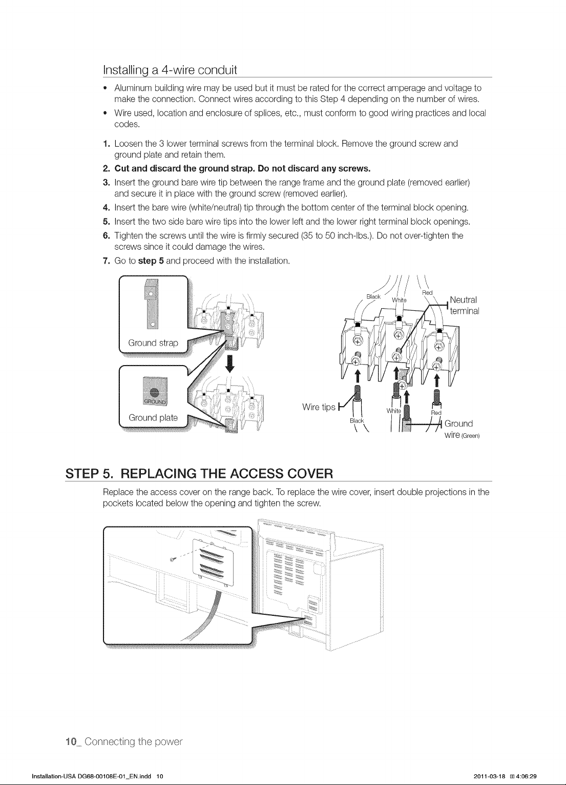
.
Loosen
the
3
lower
terminal
screws
from
the
terminal
block.
Remove
the
ground
screw
and
ground
plate
and
retain
them.
.
Cut
and
discard
the
ground
strap.
Do
not
discard
any
screws.
.
Insert
the
ground
bare
wire
tip
between
the
range
frame
and
the
ground
plate
(removed
earlier)
and
secure
it
in
place
with
the
ground
screw
(removed
earlier).
.
Insert
the
bare
wire
(white/neutral)
tip
through
the
bottom
center
of
the
terminal
block
opening.
.
Insert
the
two
side
bare
wire
tips
into
the
lower
left
and
the
lower
right
terminal
block
openings.
.
Tighten
the
screws
until
the
wire
is
firmly
secured
(35
to
50
inch-lbs.).
Do
not
over-tignten
the
screws
since
it
could
damage
the
wires.
.
Go
to
step
5
and
proceed
with
the
installation.
ZAI
Ground
strap
Wire
tips
Ground
wire
(Green)
Ground
plate
STEP
5.
REPLACING
THE
ACCESS
COVER
Replace
the
access
cover
on
the
range
back.
To
replace
the
wire
cover,
insert
double
projections
in
the
pockets
located
below
the
opening
and
tighten
the
screw.
10_
Connecting
the
power
Installation-USA
DG68-00108E-01_EN.indd
10
2011-03-18
i
4:06:29
Installing
the
range
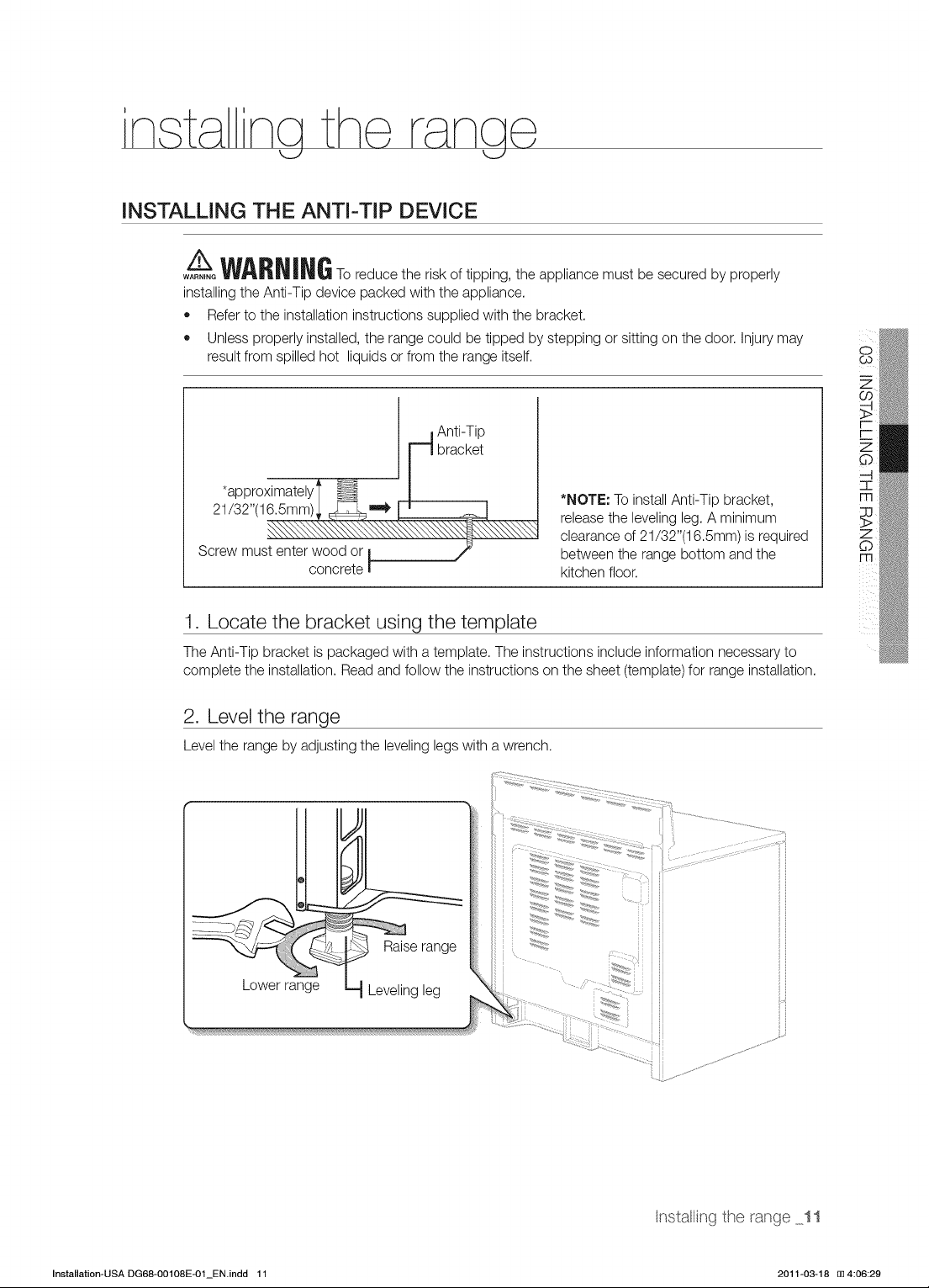
INSTALLING
THE
ANTI-TIP
DEVICE
A
WARN
ING
To
reduce
the
risk
of
tipping,
the
appliance
must
be
secured
by
properly
installing
the
Anti-Tip
device
packed
with
the
appliance.
@
Refer
to
the
installation
instructions
supplied
with
the
bracket.
e
Unless
properly
installed,
the
range
could
be
tipped
by
stepping
or
sitting
on
the
coor.
Injury
may
result
from
spilled
hot liquids
or
from
the
range
itself. sc
Zz
~”
>
Anti-Tip
ro
bracket
6
*
OO
=
/
5
e't6
samy
*NOTE:
To
install
Anti-Tip
bracket,
m
.
release
the
leveling
leg.
A
minimum
x
clearance
of
21/32”(16.5mm)
is
required
Zz
Screw
must
enter
wood
or
between
the
range
bottom
and
the
©
concrete
kitchen
floor.
1.
Locate
the
bracket
using
the
template
The
Anti-Tip
bracket
is
packaged
with
a
template.
The
instructions
include
information
necessary
to
complete
the
installation.
Read
and
follow
the
instructions
on
the
sheet
(template)
for
range
installation.
2.
Level
the
range
Level
the
range
by
adjusting
the
leveling
legs
with
a
wrench.
C43
Raise
range
”
Lower
range
Leveling
leg
installing
the
range
11
Installation-USA
DG68-00108E-01_EN.indd
11
2011-03-18
i
4:06:29
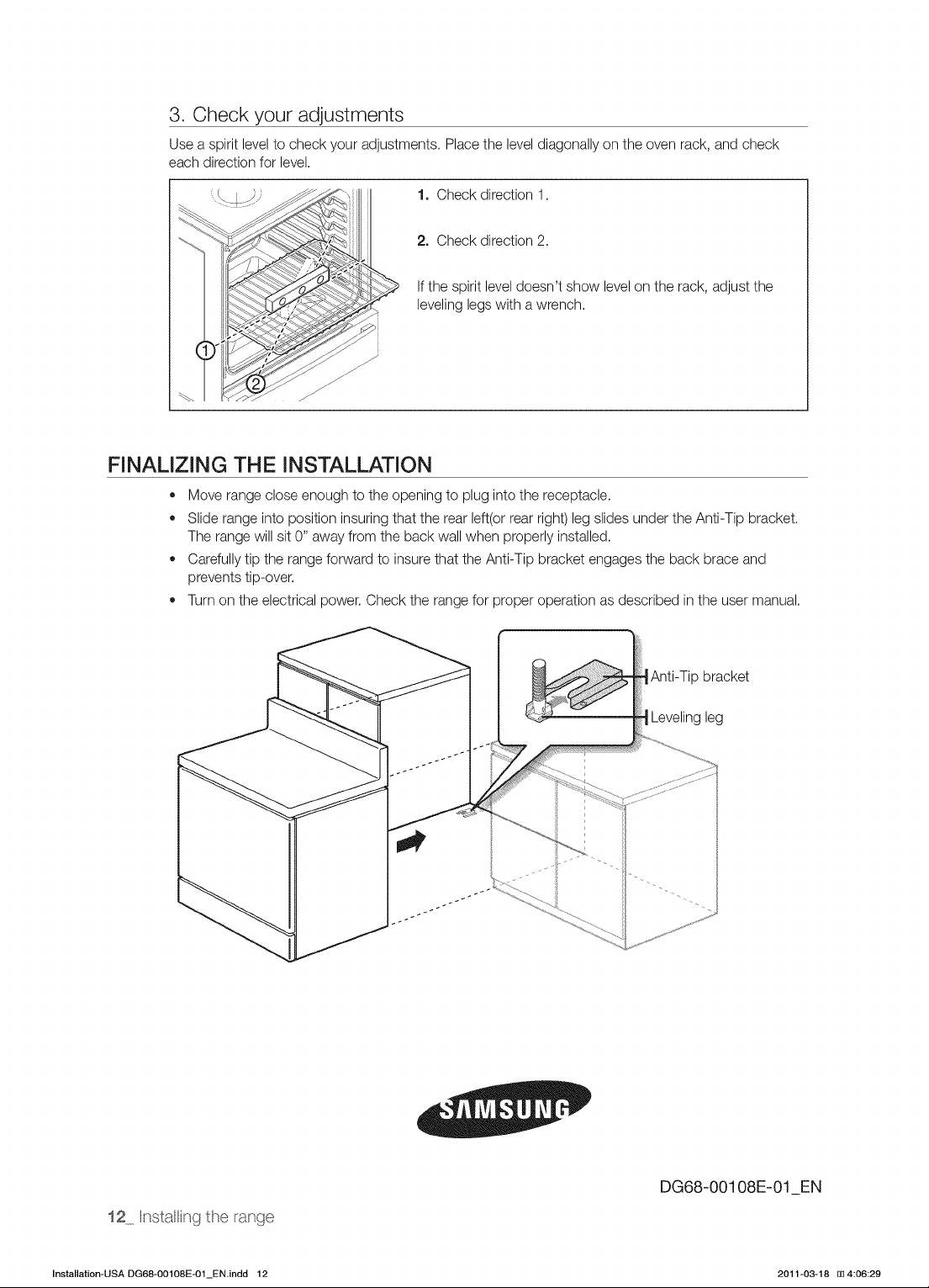
3.
Check
your
adjustments
Use
a
spirit
level
to
check
your
adjustments.
Place
the
level
diagonally
on
the
oven
rack,
and
check
each
direction
for
level.
1.
Check
direction
1.
2.
Check
direction
2.
If
the
spirit
level
doesn’t
show
level
on
the
rack,
adjust
the
leveling
legs
with
a
wrench.
FINALIZING
THE
INSTALLATION
@
Move
range
close
enough
to
the
opening
to
plug
into
the
receptacle.
®
Slide
range
into
position
insuring
that
the
rear
left(or
rear
right)
leg
slides
under
the
Anti-Tip
bracket.
The
range
will
sit
0”
away
from
the
back
wall
when
properly
installed.
®
Carefully
tip
the
range
forward
to
insure
that
the
Anti-Tip
bracket
engages
the
back
brace
and
prevents
tip-over.
@
Turn
on
the
electrical
power.
Check
the
range
for
proper
operation
as
described
in
the
user
manual.
Anti-Tip
bracket
“Leveling
leg
DG68-00108E-01_EN
42_
Installing
the
range
Installation-USA
DG68-00108E-01_EN.indd
12
2011-03-18
i
4:06:29