Loading ...
Loading ...
Loading ...
- Open Circuit Voltage: 0.25V
- Overload Protection: 250V DC or 250V rms AC
- Open circuit voltage: approx. 0.5V
- Overload Protection: 250V DC or 250V rms AC
- Overload Protection: 250V DC or rms AC
Resistance
Range Accuracy Resolution
200Ω ±(1.0% rdg + 5 digits) 0.1Ω
2kΩ 0.001kΩ
20kΩ ±(1.0% rdg + 2 digits) 0.01kΩ
200kΩ 0.1kΩ
2MΩ 0.001MΩ
20MΩ ±(1.2% rdg + 5 digits) 0.01MΩ
Engine Dwell
Range Accuracy Resolution
4CYL ±(3º ) 0.1º
6CYL ±(3º ) 0.1º
8CYL ±(3º ) 0.1º
- Overload Protection: 250V DC or rms AC
Engine Rev
Range Accuracy Resolution
4CYL 10RPM
6CYL ±(3.0% rdg + 3 digits) 10RPM
8CYL 10RPM
Continuity Test
Range Function
Built-in buzzer will sound, if resistance
is lower than 50Ω
- Forward DC Current: approx. 1mA
- Reversed DC Voltage: approx.1.5V
- Overload Protection: 250V DC or rms AC
Diode
Range Resolution Function
1mV.
Display: read approximate forward
voltage of diode.
8.11 RESISTANCE (Ω)
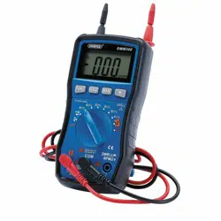
1. Connect the black test lead to the COM probe socket and the red test lead to the V/Ω
probe socket.
2.
Set the measurement fuction range switch to the Ω position.
Notes:
If the resistance is more than 1MΩ, the meter will need several seconds to staberlise its
readings.
8.12 MEASURING ENGINE DWELL
1. Connect the black test lead to the COM probe socket and the red test lead to the V/Ω
probe socket.
2.
Set the measurement fuction range switch to the desired DWELL range position.
8.13 MEASURING REV
1. Connect the black test lead to the COM probe socket and the red test lead to the V/Ω
probe socket.
2. Set the
measurement fuction range switch to the desired TACH range position.
8.14 TESTING DIODE
1. Connect the black test lead to the COM probe socket and the red test lead to the V/Ω
probe socket.
2. Set the
measurement fuction range switch to " " position.
3. Press the "FUNC." key to switch to test.
8.15 CONTINUITY TEST
WARNING
When testing the circuit continuity, be sure that the power to the circuit has been
shut down and all capacitors have been discharged fully.
1. Connect the black test lead to the COM probe socket and the red test lead to the V/Ω
probe socket.
2. Set the measurement fuction range switch to the position.
3. Press the "FUNC." key to switch the continuity test.
Note:
If the circuit is open (or the circuit resistance is higher than 200Ω ), then the figure '0L'
will be displayed.
4. INTRODUCTION
8. OPERATING INSTRUCTIONS
7
14
Loading ...
Loading ...
Loading ...