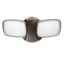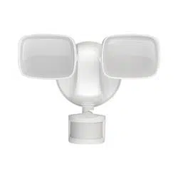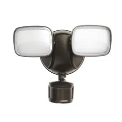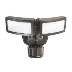
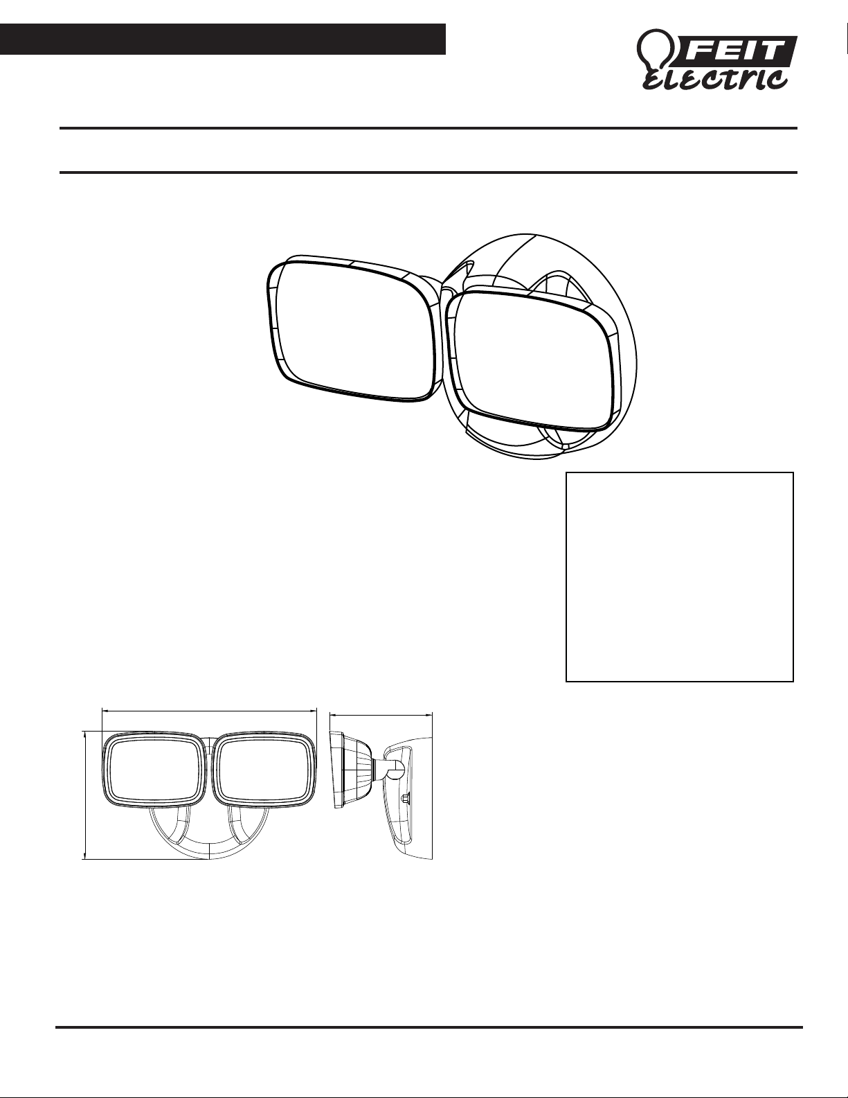
DUAL HEAD FLOOD LIGHT INSTALLATION INSTRUCTIONS
MODEL S9DFL/850/BZ/V1 & S9DFL/850/WH
FEIT ELECTRIC COMPANY | PICO RIVERA, CA | (800) 543-3348 | FAX (562) 908-6360 | www.feit.com
WARNING: These products may represent a possible shock or fire hazard if improperly installed or attached in any way.
Products should be installed in accordance with the owners manual, current electrical codes and/or the current National
Electric Code (NEC).
CAUTION, IMPORTANT SAFETY INSTRUCTIONS -
Make sure the supply voltage is the
same as the rated luminaire voltage. Do not install where marked operating temperatures
exceed the ignition temperature of the hazardous atmosphere. Do not operate in ambient
temperatures above those indicated on the luminaire nameplate. To avoid the risk of fire,
explosion, or electric shock, this product should be installed, inspected and maintained by a
qualified electrician only, in accordance with all applicable electrical codes. Be certain
electrical power is OFF before and during installation and maintenance.
Note: Save these instructions for future reference.
For supply connections use wire rated for at least 90°C
CAUTION: Input 120VAC
PARTS INCLUDED
(1) Flood light
(1) Crossbar
(2) J-Box mounting screws
(2) Fixture mounting screws
(2) Rubber washers
(2) Canopy mounting nuts
(2) Wire nuts
(1) Round plate
LIMITED WARRANTY
This product is warranted to be free from
defects in workmanship and materials for up
to 5 years from date of purchase. If it fails to
do so, please contact Feit Electric at
[email protected]om or call 1-866 326-BULB (2852)
for instructions on replacement. Do not
return the product to the store.
For comments please write to:
Feit Electric
Customer Service Department
4901 Gregg Road, Pico Rivera, CA 90660
This device complies with part 15 of the FCC Rules. Operation is subject to
the following two conditions: (1) This device may not cause harmful
interference, and (2) this device must accept any interference received,
including interference that may cause undesired operation. Note: This
equipment has been tested and found to comply with the limits for a Class B
digital device, pursuant to part 15 of the FCC Rules. These limits are
designed to provide reasonable protection against harmful interference in a
residential installation. This equipment generates, uses and can radiate radio
frequency energy and, if not installed and used in accordance with the
instructions, may cause harmful interference to radio communications.
However, there is no guarantee that interference will not occur in a particular
installation. If this equipment does cause harmful interference to radio or
television reception, which can be determined by turning the equipment off
and on, the user is encouraged to try to correct the interference by one or more
of the following measures: Reorient or relocate the receiving antenna. Increase
the separation between the equipment and receiver. Connect the equipment
into an outlet on a circuit different from that to which the receiver is connected.
Consult the dealer or an experienced radio/TV technician for help.
8.9 in / 226.1mm
5.3 in / 134.7mm
4.25 in / 108.1mm
REV003
MODEL S9DFL/850/BZ/V1 & S9DFL/850/WH
FEIT ELECTRIC COMPANY | PICO RIVERA, CA | (800) 543-3348 | FAX (562) 908-6360 | www.feit.com
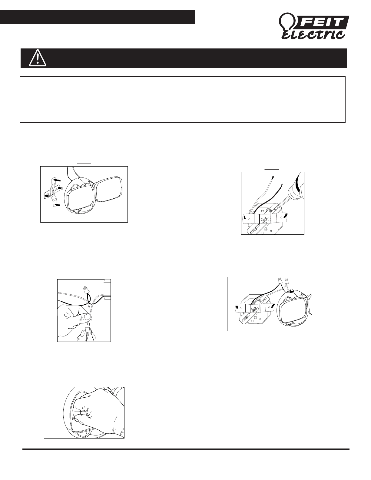
Wall Mount Installation
Fig D.
Fig B.
WARNING: TURN OFF THE MAIN POWER AT THE CIRCUIT BREAKER BEFORE
INSTALLING THE FIXTURE IN ORDER TO PREVENT POSSIBLE ELECTRIC SHOCK.
WARNING:
This luminaire should be installed by qualified electrician. To avoid the risk of fire, explosion or electric shock, this product
should be installed, inspected and maintained by a qualified electrician only, in accordance with all applicable electrical codes.
To avoid electric shock: Be certain electrical power is OFF before and during installation and maintenance.
Make sure the supply voltage is the same as the rated luminaire voltage. Do not operate in ambient temperatures above those indicated on
the luminaire nameplate. Keep lens tightly closed when in operation.
1. Unscrew the canopy mounting nuts and remove the fixture
crossbar (Fig A).
2. Pull the power supply wires to the side and install the fixture
crossbar onto the J -box with the screws provided. Connect
the ground wire to the ground screw on the crossbar (Fig B).
3. Using the wire nuts provided, connect the white fixture wire to
the neutral house wire. Connect the black fixture wire to the power
supply wire (Fig C).
5. Position into place and secure fixture by installing the rubber
washers and the canopy mounting nuts, then tighten the nuts (Fig E).
6. Caulk between the light fixture and the wall surface with a
silicone sealant (not included).
4. Adjust the crossbar fixture screws and tighten the center
swivel screws. Insert the canopy holes through fixture
mounting screws (Fig D).
Fig A.
Fig C.
Fig E.
MODEL S9DFL/850/BZ/V1 & S9DFL/850/WH
FEIT ELECTRIC COMPANY | PICO RIVERA, CA | (800) 543-3348 | FAX (562) 908-6360 | www.feit.com
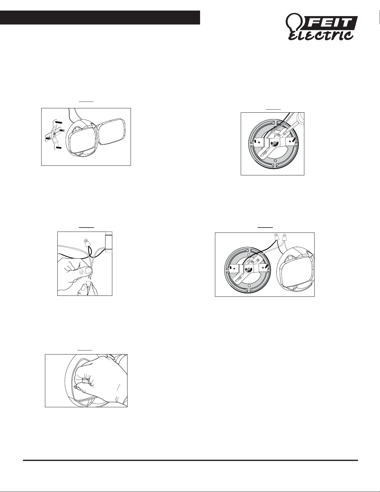
4" Round External J-box Installation
2. Pull the power supply wires to the side and install the fixture
crossbar onto the J -box with the screws provided. Connect
the ground wire to the ground screw on the crossbar (Fig B).
1. Unscrew the canopy mounting nuts and remove the fixture
crossbar (Fig A).
2. Before installing the round plate, add silicone sealant between
the rear of the round plate and the J-box. Pull the power supply
wires through the round plate and install the round plate along
with crossbar, onto the J -box with the screws provided. Connect
the ground wire to the ground screw on the crossbar (Fig B).
3. Using the wire nuts provided, connect the white fixture wire to
the neutral house wire. Connect the black fixture wire to the power
supply wire (Fig C).
4. Adjust the crossbar fixture screws and tighten the center swivel
screws. Before installing the fixture canopy, add silicone sealant
between the front of the round plate and fixture canopy. Insert the
fixture canopy holes through fixture mounting screws (Fig D).
5. Position into place and secure fixture by installing the rubber
washers and the canopy mounting nuts, then tighten the nuts (Fig E).
Fig A.
Fig B.
Fig C. Fig D.
Fig E.