
Owner's Manual
CRRFTSMRN'°
27.0 HP, 54" Mower
Electric Start
Automatic Transmission
Model No.
917.276120
_]]] his product has a mowemission engine which operates
differentmy from previousmy buimt engines. Before you start the
engine, read and understand this Owner's Manuak
Read and follow aH Safety
Rules and Instructions before
operating this equipment.
For answers to your questions about
th_ product, Ca,,:
1 800 659 5917
Sears Craftsman Help Line
5 am =5 pm, Mort = Sat
Sears, Roebuck and Co., Hoffman Estates, IL 60179 U.S.A.
Visit our Craftsman website: www.sears.com/craftsman
Warranty ................................................ 2
Safety Rules .......................................... 3
Product Specifications ........................... 6
Assembly/Pre-Operation ....................... 8
Operation ............................................. 12
Maintenance Schedule ........................ 19
Maintenance ........................................ 19
Service and Adjustments ..................... 23
Storage ................................................ 31
Troubleshooting ................................... 32
Repair Parts ......................................... 36
Sears Service ........................ Back Cover
LIMITED WARRANTY ON CRAFTSMAN RIDING EQUIPMENT
For two (2) years from the date of purchase, if this Craftsman Riding Equipment is
maintained, lubricated and tuned up according to the instructions in the owner's manual,
Sears will repair or replace free of charge any parts that are found to be defective in
material or workmanship according to the guidelines of coverage listed below. Sears will
also provide free labor for these applicable warranted parts for the two full years. During
the first 30 days of purchase, there will be no charges to service the product at your
home for issues covered by this warranty. (See exclusions below). For your conve-
nience, IN HOME warranty service will still be available after the first 30 days of pur-
chase, but a trip charge will apply. This charge will be waived if the Craftsman product is
dropped off at an authorized Sears location. For the nearest authorized Sears location,
please call 1-800-4-MY-HOME@. This warranty applies only while this product is within
the United States.
This Warranty does not cover:
Expendable items which become worn during normal use, including but not limited to
blades, spark plugs, air cleaners, belts, and oil filters.
Standard Maintenance Servicing, oil changes, or tune-ups
Tire replacement or repair caused by punctures from outside objects, such as nails,
thorns, stumps, or glass.
Repairs necessary because of operator abuse, including but not limited to, damage
caused by towing objects beyond the capability of the riding equipment, impacting
objects that bend the frame or crankshaft, or over-speeding the engine.
Repairs necessary because of operator negligence, including but not limited to, elec-
trical and mechanical damage caused by improper storage, failure to use the proper
grade and amount of engine oil, failure to keep the deck clear of flammable debris,
or failure to maintain the equipment according to the instructions contained in the
owner's manual.
• Engine (fuel system) cleaning or repairs caused by fuel determined to be contami-
nated or oxidized (stale). In general, fuel should be used within 30 days of its pur-
chase date.
• Normal deterioration and wear of the exterior finishes, or product label replacement.
• Riding equipment used for commercial or rental purposes.
LIMITED WARRANTY ON BATTERY
For ninety (90) days from date of purchase, if any battery included with this riding equip-
ment proves defective in material or workmanship and our testing determines the battery
will not hold a charge, Sears will replace the battery at no charge. During the first 30
days of purchase, there will be no charges to replace the battery at your HOME. After
the first 30 days, for your convenience, IN-HOME warranty service will still be avail-
able but a trip charge will apply. This charge will be waived if the Craftsman product is
dropped off at an authorized Sears location. For the nearest authorized Sears location,
please call 1-800-4-MY-HOME@.
This battery warranty applies only while this product is within the United States.
This warranty gives you specific legal rights, and you may also have other rights, which
vary, from state to state.
Sears, Roebuck and Co.,Dept.817WA, Hoffman Estates, IL 60179
2
mMPORTANT: This cutting machine is capable of amputating hands and feet and throw-
ing objects. Failure to observe the following safety instructions could result in serious
injury or death.
AI_WARNING: In order to prevent ac-
cidental starting when setting up, trans-
porting, adjusting or making repairs,
always disconnect spark plug wire and
place wire where it cannot contact spark
,_i,ug"
WARNmNG: Do not coast down a hill in
neutral, you may lose control of the tractor.
AI_WARNmNG: Tow only the attachments
that are recommended by and comply with
specifications of the manufacturer of your
tractor. Use common sense when towing.
Operate only at the lowest possible speed
when on a slope. Too heavy of a load,
while on a slope, is dangerous. Tires can
lose traction with the ground and cause
u to lose control of your tractor.
WARNmNG: Engine exhaust, some of its
constituents, and certain vehicle compo-
nents contain or emit chemicals known to
the State of California to cause cancer and
birth defects or other reproductive harm.
_WARNmNG: Battery posts, terminals
and related accessories contain lead and
lead compounds, chemicals known to the
State of California to cause cancer and
birth defects or other reproductive harm.
Wash hands after handling,
L GENERAL OPERATmON
* Read, understand, and follow all instruc-
tions in the manual and on the machine
before starting.
Only allow responsible adults, who are
familiar with the instructions, to operate
the machine.
* Clear the area of objects such as rocks,
toys, wire, etc., which could be picked
up and thrown by the blade.
Be sure the area is clear of other people
before mowing. Stop machine if anyone
enters the area.
* Never carry passengers.
* Do not mow in reverse unless abso-
lutely necessary. Always look down and
behind before and while backing.
Be aware of the mower discharge direc-
tion and do not point it at anyone. Do
not operate the mower without either
the entire grass catcher or the guard in
place.
* Slow down before turning.
Never leave a running machine unat-
tended. Always turn off blades, set
parking brake, stop engine, and remove
keys before dismounting.
Turn off blades when not mowing.
Stop engine before removing grass
catcher or unclogging chute.
Mow only in daylight or good artificial
light.
Do not operate the machine while under
the influence of alcohol or drugs.
Watch for traffic when operating near or
crossing roadways.
Use extra care when loading or un-
loading the machine into a trailer or
truck.
Data indicates that operators, age 60
years and above, are involved in a large
percentage of riding mower-related in-
juries. These operators should evaluate
their ability to operate the riding mower
safely enough to protect themselves and
others from serious injury.
* Keep machine free of grass, leaves or
other debris build-up which can touch
hot exhaust / engine parts and burn. Do
not allow the mower deck to plow leaves
or other debris which can cause build-
up to occur. Clean any oil or fuel
spillage before operating or storing the
machine. Allow machine to cool before
storage.
H. SLOPE OPERATION
Slopes are a major factor related to loss-
of-control and tipover accidents, which can
result in severe injury or death. All slopes
require extra caution. If you cannot back
up the slope or if you feel uneasy on it, do
not mow it.
3

DO:
, Mow up and down slopes, not across.
Remove obstacles such as rocks, tree
limbs, etc.
Watch for holes, ruts, or bumps. Un-
even terrain could overturn the machine.
Taft grass can hide obstacles.
Use slow speed. Choose a low gear
so that you will not have to stop or shift
while on the slope.
Follow the manufacturer's recommend-
ations for wheel weights or counter-
weights to improve stability.
Use extra care with grass catchers or
other attachments. These can change
the stability of the machine.
Keep all movement on the slopes slow
and gradual Do not make sudden
changes in speed or direction.
Avoid starting or stopping on a slope. If
tires lose traction, disengage the blades
and proceed slowly straight down the
slope.
DO NOT:
Do not turn on slopes unless neces-
sary, and then, turn slowly and gradually
downhill, if possible.
Do not mow near drop-offs, ditches,
or embankments. The mower could
suddenly turn over if a wheel is over
the edge of a cliff or ditch, or if an edge
caves in.
Do not mow on wet grass. Reduced
traction could cause sliding.
Do not try to stabilize the machine by
putting your foot on the ground.
Do not use grass catcher on steep
slopes.
ill. CHILDREN
Tragic accidents can occur if the operator
is not alert to the presence of children.
Children are often attracted to the ma-
chine and the mowing activity. Never as-
sume that children wi[[ remain where you
last saw them.
Keep children out of the mowing area
and under the watchful care of another
responsible adult.
Be alert and turn machine off if children
enter the area.
Before and when backing, look behind
and down for small children.
Never carry children. They may fall off
and be seriously injured or interfere with
safe machine operation.
Never allow children to operate the
machine.
Use extra care when approaching blind
corners, shrubs, trees, or other objects
that may obscure vision.
iV. SERVICE
Use extra care in handling gasoline and
other fuels. They are flammable and
vapors are explosive.
-Use only an approved container.
- Never remove gas cap or add fuel
with the engine running. Allow
engine to cool before refueling. Do
not smoke.
-Never refuel the machine indoors.
- Never store the machine or fuel
container inside where there is an
open flame, such as a water heater.
Never run a machine inside a closed
area.
Keep nuts and bolts, especially blade
attachment bolts, tight and keep equip-
ment in good condition.
Never tamper with safety devices.
Check their proper operation regularly.
Keep machine free of grass, leaves, or
other debris build-up. Clean oil or fuel
spillage. Allow machine to cool before
storing.
Stop and inspect the equipment if you
strike an object. Repair, if necessary,
before restarting.
Never make adjustments or repairs with
the engine running.
Grass catcher components are subject
to wear, damage, and deterioration,
which could expose moving parts or
allow objects to be thrown. Frequently
check components and replace with
manufacturer's recommended parts,
when necessary.
Mower blades are sharp and can cut.
Wrap the blade(s) or wear gloves, and
use extra caution when servicing them.
Check brake operation frequently. Ad-
just and service as required.

Be sure the area is clear of other people
before mowing.Stop machineif anyone
enters the area.
Nevercarry passengersor children
evenwith the bladesoff.
Do not mow in reverseunlessabso-
lutely necessary.Alwayslook down and
behind beforeand while backing.
Nevercarry children.Theymayfall off
and be seriously injuredor interferewith
safe machineoperation.
Keepchildrenout of the mowingarea
and underthe watchfulcare of another
responsibleadult.
Be alert and turn machineoff if children
enter the area.
Beforeand when backing, look behind
and down for small children.
Mow up and down slopes (15° Max), not
across.
Remove obstacles such as rocks, tree
limbs, etc.
Watch for holes, ruts, or bumps. Uneven
terrain could overturn the machine. Tall
grass can hide obstacles.
Use slow speed. Choose a low gear
so that you will not have to stop or shift
while on the slope.
Avoid starting or stopping on a slope. If
tires lose traction, disengage the blades
and proceed slowly straight down the
slope.
If machine stops while going uphill,
disengage blades, shift into reverse and
back down slowly.
Do not turn on slopes unless necessary,
and then, turn slowly and gradually
downhill, if possible.
5
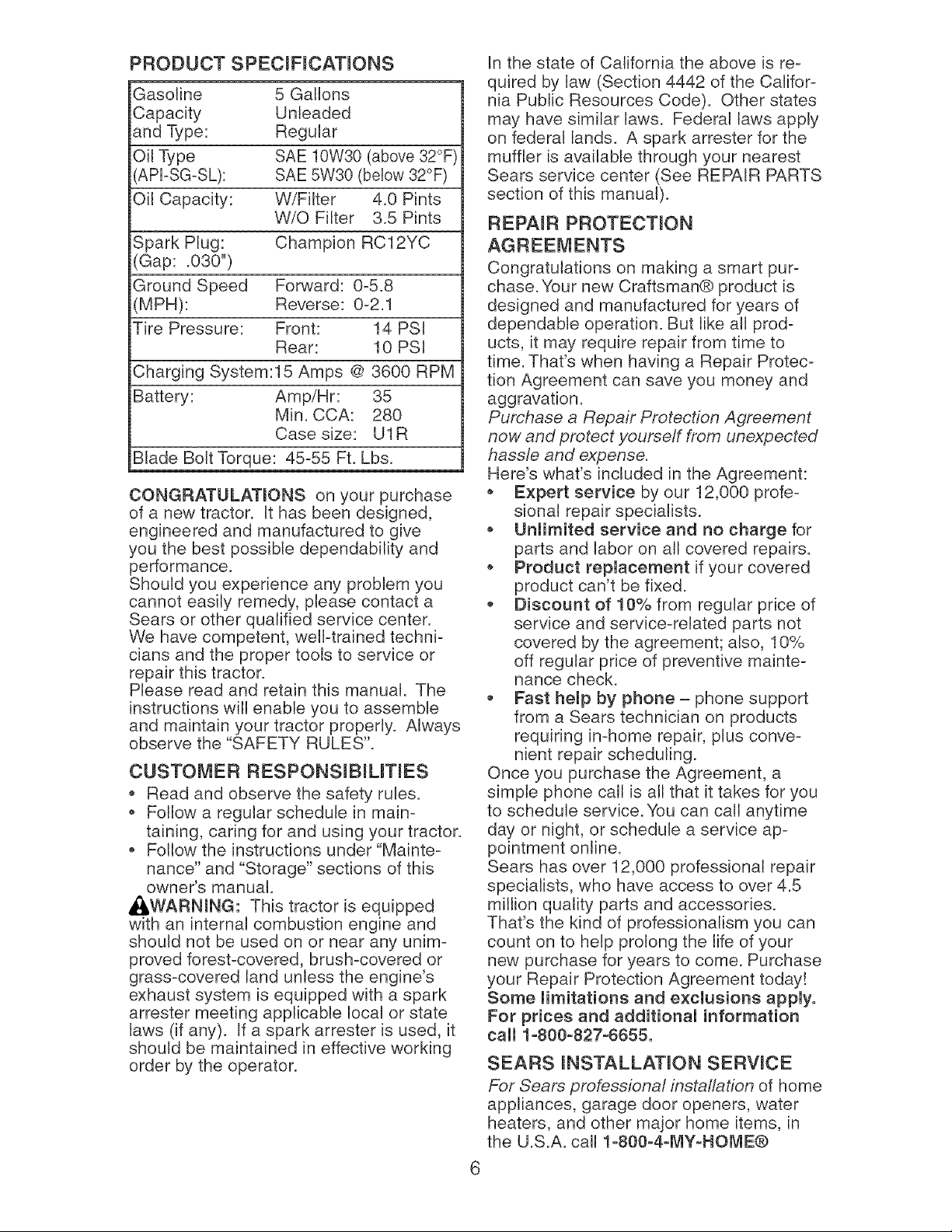
PRODUCT SPECIFICATmONS
Gasoline 5 Gallons
Capacity Unleaded
and Type: Regular
Oil Type SAE 10W30 (above 32°F
APFSG-SL): SAE 5W30 (bellow 32°F)
Oil Capacity: W/Filter 4.0 Pints
W/O Filter 3.5 Pints
Spark Plug: Champion RC12YC
(Gap: .030")
Ground Speed Forward: 0=5.8
(MPH): Reverse: 0=2.1
Tire Pressure: Front: 14 PSI
Rear: 10 PSI
Charging System:15 Amps @ 3600 RPM
Battery: Amp/Hr: 35
Min. CCA: 280
Case size: U1R
Blade Bolt Torque: 45%5 Ft. Lbs.
CONGRATULATmONS on your purchase
of a new tractor. It has been designed,
engineered and manufactured to give
you the best possible dependability and
performance.
Should you experience any problem you
cannot easily remedy, please contact a
Sears or other qualified service center.
We have competent, well-trained techni=
cians and the proper tools to service or
repair this tractor.
Please read and retain this manual. The
instructions will enable you to assemble
and maintain your tractor properly. Always
observe the "SAFETY RULES".
CUSTOMER RESPONSIBILITIES
Read and observe the safety rules.
* Follow a regular schedule in main-
taining, caring for and using your tractor.
* Follow the instructions under"Mainte-
nance" and "Storage" sections of this
owner's manual.
A(_WARNING: This tractor is equipped
with an internal combustion engine and
should not be used on or near any unim-
proved forest-covered, brush-covered or
grass-covered land unless the engine's
exhaust system is equipped with a spark
arrester meeting applicable local or state
laws (if any). If a spark arrester is used, it
should be maintained in effective working
order by the operator.
In the state of California the above is re-
quired by law (Section 4442 of the Califor-
nia Public Resources Code). Other states
may have similar laws. Federal laws apply
on federal lands. A spark arrester for the
muffler is available through your nearest
Sears service center (See REPAIR PARTS
section of this manual).
REPAIR PROTECTmON
Congratulations on making a smart pur-
chase. Your new Craftsman® product is
designed and manufactured for years of
dependable operation. But like all prod-
ucts, it may require repair from time to
time. That's when having a Repair Protec-
tion Agreement can save you money and
aggravation.
Purchase a Repair Protection Agreement
now and protect yourseff from unexpected
hassle and expense.
Here's what's included in the Agreement:
* Expert service by our 12,000 profe-
sionat repair specialists.
* Unlimited service and no charge for
parts and labor on all covered repairs.
* Product replacement if your covered
product can't be fixed.
Discount of 10% from regular price of
service and service=related parts not
covered by the agreement; also, 10%
off regular price of preventive mainte=
nance check.
Fast hemp by phone = phone support
from a Sears technician on products
requiring in=home repair, plus conve=
nient repair scheduling.
Once you purchase the Agreement, a
simple phone call is all that it takes for you
to schedule service. You can call anytime
day or night, or schedule a service ap=
pointment online.
Sears has over 12,000 professional repair
specialists, who have access to over 4.5
million quality parts and accessories.
That's the kind of professionalism you can
count on to help prolong the life of your
new purchase for years to come. Purchase
your Repair Protection Agreement today!
Some limitations and exclusions apply.
For prices and additional information
call 1o800o827o6655.
SEARS mNSTALLATmON SERWCE
For Sears professional installation of home
appliances, garage door openers, water
heaters, and other major home items, in
the U.S.A. call l oS00o4oMYoHOME®
Steering Wheel
Steering
Wheel
Insert
Gauge Wheels
(i) Adjusting
Bar
_i Steering
Steering Extension
Steering Sleeve Shaft
Wheel
Adapter
(4) Retainer Springs
(double loop)
r
0
0
@
(4) Washers
3/8 x 3/4 x 14 Ga. (4) Locknut 3/8-16
I
(4) Wheels
Ir
(4) Clevis Pins
-- (4) Shoulder Bolt
Mower Leveling Wrench
t
' IIIIIIIIIIIIIIIIIIIIIIIIIII
(4) Hex Bolts 5/16-18 x 3/4
(4) Lockwasher
Nose Roller
(2) Hex Bolts
Spring
5/16-18 x 1
(1) Oil Drain Tube
For Future Use Slope Sheet
Keys
Mower
(2) Retainer Springs
(double loop)
,%
(2)Flanged Pins
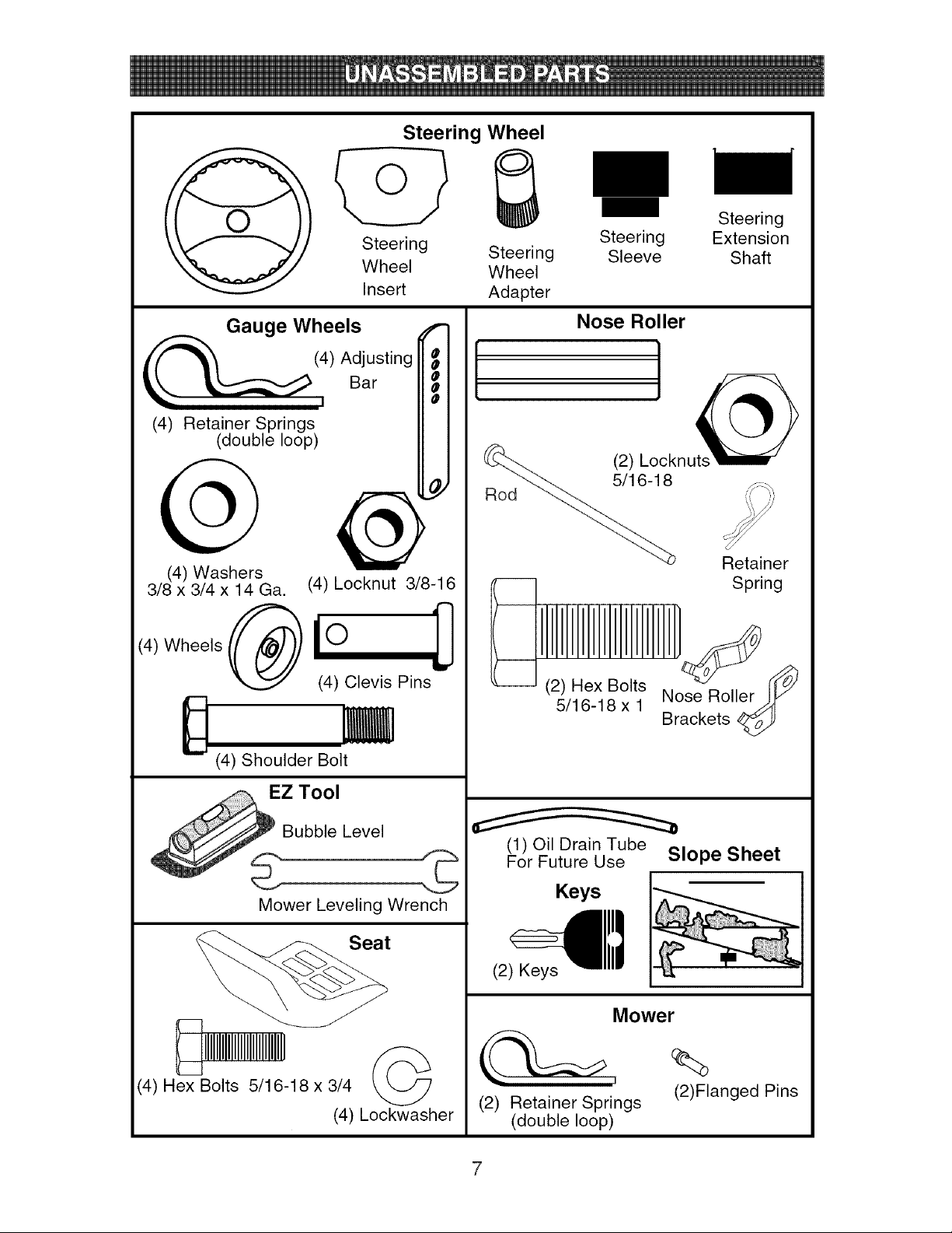
Your newtractor has been assembledat the factory with the exceptionof those parts left
unassembledfor shippingpurposes.Toensuresafe and proper operationof your tractor
all parts and hardwareyou assemblemust be tightenedsecurely.Use the correcttools
as necessaryto insure propertightness.Reviewthe videocassette beforeyou begin.
TOOLS REQUIREDFOR ASSEMBLY
A socket wrenchset will makeassembly
easier. Standardwrenchsizes you need
are listedbelow.
(1) 9/16" wrench (1) Pliers
(1) 1/2" wrench (1) Utility knife
(1) 3/4" socketwith drive ratchet
(1) Tire pressure gauge
When right or left hand is mentionedin
this manual,it means,from your pointof
view, whenyou are in the operatingposi-
tion (seated behindthe steeringwheel).
TO REMOVE TRACTOR FROM
CARTON
UNPACK CARTON
1. Remove all accessible loose parts and
parts boxes from carton.
2. Cut along dotted lines on all four pan-
els of carton. Remove end panels and
lay side panels flat.
3. Remove mower and packing materials.
4. Check for any additional loose parts or
cartons and remove.
BEFORE REMOVING TRACTOR
FROM SKID
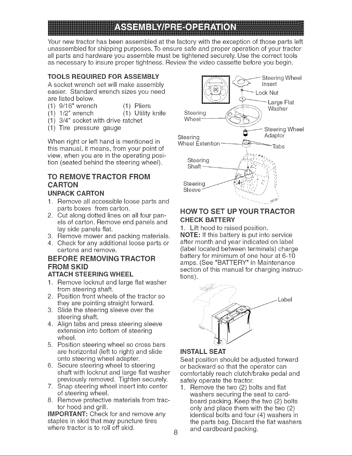
ATTACH STEERmNG WHEEL
1. Remove Iocknut and large flat washer
from steering shaft.
2. Position front wheels of the tractor so
they are pointing straight forward.
3. Slide the steering sleeve over the
steering shaft.
4. Align tabs and press steering sleeve
extension into bottom of steering
wheel.
5. Position steering wheel so cross bars
are horizontal (left to right) and slide
onto steering wheel adapter.
6. Secure steering wheel to steering
shaft with Iocknut and large flat washer
previously removed. Tighten securely.
7. Snap steering wheel insert into center
of steering wheel.
8. Remove protective materials from trac-
tor hood and grill.
mMPORTANT: Check for and remove any
staples in skid that may puncture tires
where tractor is to roll off skid.
_ _- .... Steering Wheel
_,.b__ insert
Lock Nut
.................Large Fiat
Washer
Steering _ ' _
Steering Wheel
Adaptor
Steering
Wheel Extention __Tabs
Steering
Shaft
Steering
Sleeve
HOW TO SET UP YOUR TRACTOR
CHECK BATTERY
1. Lift hood to raised position.
NOTE: If this battery is put into service
after month and year indicated on label
(label located between terminals) charge
battery for minimum of one hour at 6-10
amps. (See "BATTERY" in Maintenance
section of this manual for charging instruc-
tions).
/ . ,
- • __ Label
INSTALL SEAT
Seat position should be adjusted forward
or backward so that the operator can
comfortably reach clutch/brake pedal and
safely operate the tractor.
1. Remove the two (2) bolts and flat
washers securing the seat to card-
board packing. Keep the two (2) bolts
only and place them with the two (2)
identical bolts and four (4) washers in
the parts bag. Discard the flat washers
and cardboard packing.
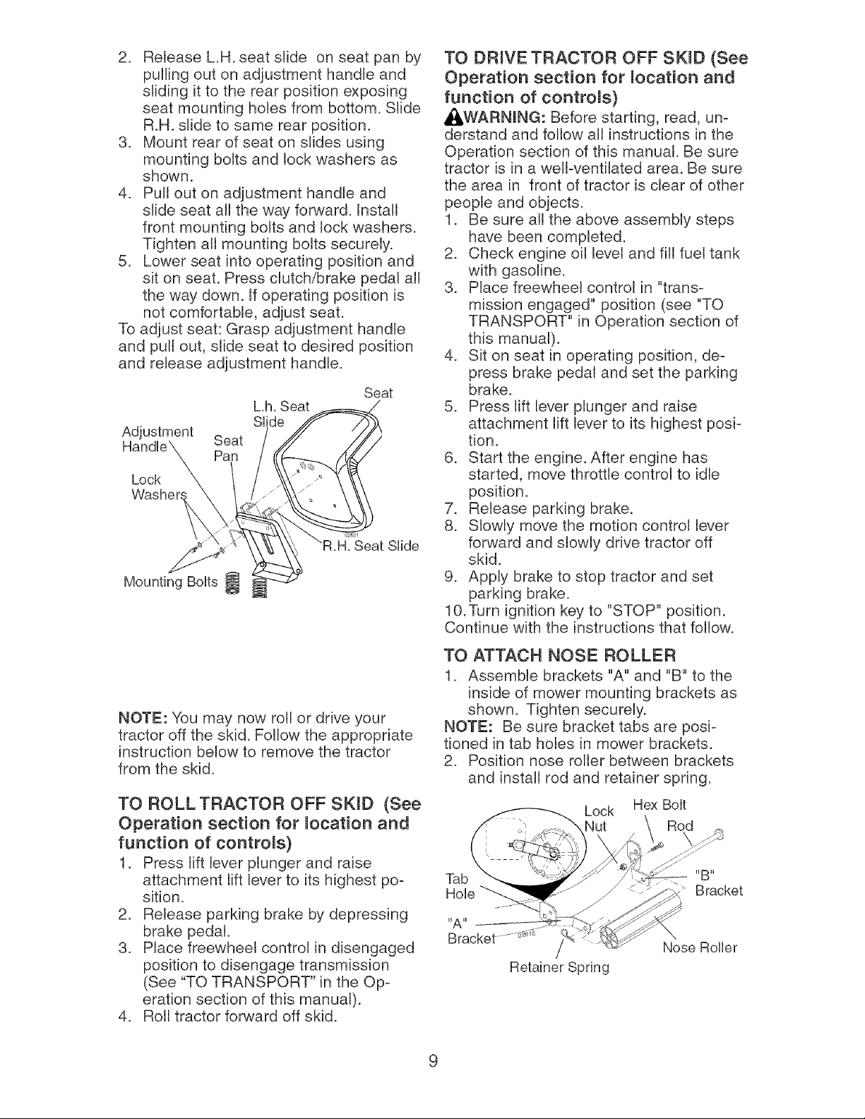
2. ReleaseL.H.seat slide on seat pan by
pullingout on adjustmenthandleand
sliding it to the rear positionexposing
seat mountingholes from bottom.Slide
R.H.slide to same rear position.
3. Mount rear of seat on slides using
mountingbolts and lockwashersas
shown.
4. Pull out on adjustmenthandleand
slideseat all the wayforward.Install
front mountingbolts and lock washers.
Tightenall mountingbolts securely.
5. Lowerseat into operatingpositionand
sit on seat. Pressclutch/brakepedal all
the way down.If operatingpositionis
not comfortable,adjustseat.
To adjustseat: Grasp adjustmenthandle
and pull out, slide seat to desired position
and releaseadjustmenthandle.
Lock
Seat
Pan
hh. Seat
Slide
Mounting Bolts
Seat
Slide
NOTE: You may now roll or drive your
tractor off the skid. Follow the appropriate
instruction below to remove the tractor
from the skid.
TO ROLL TRACTOR OFF SKID (See
Operation section for location and
function of controls)
1. Press lift lever plunger and raise
attachment lift lever to its highest po-
sition.
2. Release parking brake by depressing
brake pedal.
3. Place freewheel control in disengaged
position to disengage transmission
(See "TO TRANSPORT" in the Op-
eration section of this manual).
4. Roll tractor forward off skid.
TO DRIVE TRACTOR OFF SKID (See
Operation section for location and
function of controls)
_WARN[NG: Before starting, read, un-
derstand and follow all instructions in the
Operation section of this manual. Be sure
tractor is in a well-ventilated area. Be sure
the area in front of tractor is clear of other
people and objects.
1. Be sure all the above assembly steps
have been completed.
2. Check engine oil level and fill fuel tank
with gasoline.
3. Place freewheel control in "trans-
mission engaged" position (see "TO
TRANSPORT" in Operation section of
this manual).
4. Sit on seat in operating position, de-
press brake pedal and set the parking
brake.
5. Press lift lever plunger and raise
attachment lift lever to its highest posi-
tion.
6. Start the engine. After engine has
started, move throttle control to idle
position.
7. Release parking brake.
8. Slowly move the motion control lever
forward and slowly drive tractor off
skid.
9. Apply brake to stop tractor and set
parking brake.
10.Turn ignition key to "STOP" position.
Continue with the instructions that follow.
TO ATTACH NOSE ROLLER
1. Assemble brackets "A" and "B" to the
inside of mower mounting brackets as
shown. Tighten securely.
NOTE: Be sure bracket tabs are posi-
tioned in tab holes in mower brackets.
2. Position nose roller between brackets
and install rod and retainer spring.
Lock Hex Bolt
Nut Rod
Tab "B"
Hole Bracket
Nose Roller
9
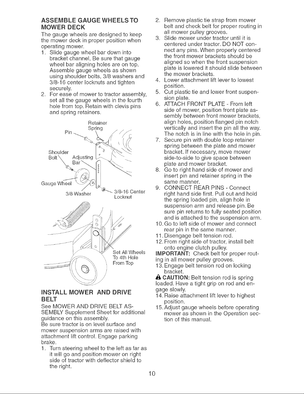
ASSEMBLE GAUGE WHEELS TO
MOWER DECK
The gauge wheels are designed to keep
the mower deck in proper position when
operating mower.
1. Slide gauge wheel bar down into
bracket channel, Be sure that gauge
wheel bar aligning holes are on top.
Assemble gauge wheels as shown
using shoulder bolts, 3/8 washers and
3/8-16 center Iocknuts and tighten
securely.
2. For ease of mower to tractor assembly,
set all the gauge wheels in the fourth
hole from top. Retain with clevis pins
and spring retainers.
Shoulder
Bolt_ Adjusting _
Gauge Wheel
3/8 Washer
@"---. 3/8-16 Center
Locknut
Set All Wheels
To 4th Hob
mNSTALL MOWER AND DRmVE
BELT
See MOWER AND DRIVE BELT AS-
SEMBLY Supplement Sheet for additional
guidance on this assembly.
Be sure tractor is on level surface and
mower suspension arms are raised with
attachment lift control. Engage parking
brake.
1. Turn steering wheel to the left as far as
it will go and position mower on right
side of tractor with deflector shield to
the right.
10
2. Remove plastic tie strap from mower
belt and check belt for proper routing in
all mower pulley grooves.
3. Slide mower under tractor until it is
centered under tractor. DO NOT con-
nect any pins. When properly centered
the front mower brackets should be
aligned so when the front suspension
plate is lowered it should slide between
the mower brackets.
4. Lower attachment lift lever to lowest
position.
5. Cut plastic tie and lower front suspen-
sion plate.
6. ATTACH FRONT PLATE - From left
side of mower, position front plate as-
sembly between front mower brackets,
align holes, position flanged pin notch
vertically and insert the pin all the way.
The notch is in line with the hole in pin.
7. Secure pin with double loop retainer
spring between the plate and mower
bracket. If necessary, move mower
side-to-side to give space between
plate and mower bracket.
8. Go to right hand side of mower and
insert pin and retainer spring in the
same manner.
9. CONNECT REAR PINS - Connect
right hand side first. Pull out and hold
the spring loaded pin, align hole in
suspension arm and release pin. Be
sure pin returns to fully seated position
and is attached to the suspension arm.
10. Go to left side of mower and connect
rear pin in the same manner.
11. Disengage belt tension rod.
12. From right side of tractor, install belt
onto engine clutch pulley.
IMPORTANT: Check belt for proper rout-
ing in all mower pulley grooves.
13. Engage belt tension rod on locking
bracket.
CAUTmON: Belt tension rod is spring
loaded. Have a tight grip on rod and en-
gage slowly.
14. Raise attachment lift lever to highest
position.
15. Adjust gauge wheels before operating
mower as shown in the Operation sec-
tion of this manual.
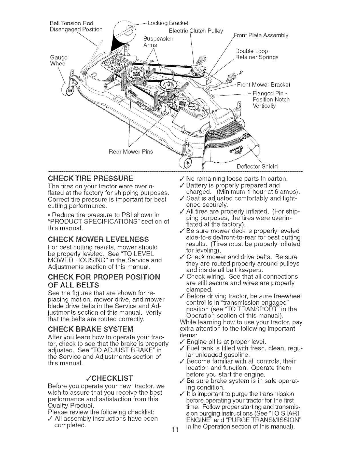
Belt Tension Rod g Bracket
Electric Clutch Pulley
Gauge
Wheel
Double Loop
Retainer Springs
...p
Front Mower Bracket
Flanged Pin °
Position Notch
Vertically
Rear Mower Pins
CHECK TIRE PRESSURE
The tires on your tractor were overin-
fiated at the factory for shipping purposes.
Correct tire pressure is important for best
cutting performance.
,, Reduce tire pressure to PSI shown in
"PRODUCT SPECIFICATIONS" section of
this manual.
CHECK MOWER LEVELNESS
For best cutting results, mower should
be properly leveled. See "TO LEVEL
MOWER HOUSING" in the Service and
Adjustments section of this manual.
CHECK FOR PROPER PosmoN
OF ALL BELTS
See the figures that are shown for re-
placing motion, mower drive, and mower
blade drive belts in the Service and Ad-
justments section of this manual. Verify
that the belts are routed correctly.
CHECK BRAKE SYSTEM
After you learn how to operate your trac-
tor, check to see that the brake is properly
adjusted. See "TO ADJUST BRAKE" in
the Service and Adjustments section of
this manual.
,/CHECKLIST
Before you operate your new tractor, we
wish to assure that you receive the best
performance and satisfaction from this
Quality Product.
Please review the following checklist:
v" All assembly instructions have been
completed.
Deflector Shield
11
v" No remaining loose parts in carton.
v" Battery is properly prepared and
charged. (Minimum 1 hour at 6 amps).
v" Seat is adjusted comfortably and tight-
ened securely.
v" All tires are properly inflated. (For ship-
ping purposes, the tires were overin-
fiated at the factory).
v" Be sure mower deck is properly leveled
side-to-sideifront-to-rear for best cutting
results. (Tires must be properly inflated
for leveling).
v" Check mower and drive belts. Be sure
they are routed properly around pulleys
and inside all belt keepers.
v" Check wiring. See that all connections
are still secure and wires are properly
clamped.
v" Before driving tractor, be sure freewheel
control is in "transmission engaged"
position (see "TO TRANSPORT" in the
Operation section of this manual).
While learning how to use your tractor, pay
extra attention to the following important
items:
v" Engine oil is at proper level.
v" Fuel tank is filled with fresh, clean, regu-
lar unleaded gasoline.
v" Become familiar with all controls, their
location and function. Operate them
before you start the engine.
v" Be sure brake system is in safe operat-
ing condition.
v" It is important to purge the transmission
before operating your tractor for the first
time. Follow proper starting and transmis-
sion purging instructions (See "TO START
ENGINE" and "PURGE TRANSMISSION"
in the Operation section of this manual).
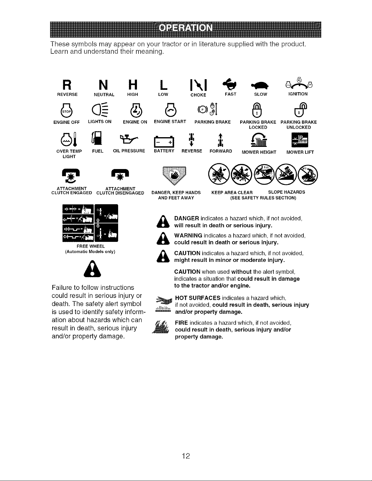
These symbols may appear on your tractor or in literaturesuppliedwith the product.
Learnand understandtheir meaning.
R N H L I\1
REVERSE NEUTRAL HIGH LOW CHOKE FAST
@ e o5I
ENGINE OFF LIGHTS ON ENGINE ON ENGINE START PARKING BRAKE
OVER TEMP FUEL OIL PRESSURE
LIGHT
ATTACHMENT ATTACHMENT
CLUTCH ENGAGED CLUTCH DISENGAGED
FREE WHEEL
(Automatic Models only)
Failure to follow instructions
could result in serious injury or
death. The safety alert symbol
is used to identify safety inform-
ation about hazards which can
result in death, serious injury
and/or property damage.
,f
BATTERY REVERSE FORWARD
SLOW IGNITION
PARKING BRAKE PARKING BRAKE
LOCKED UNLOCKED
MOWER HEIGHT MOWER LIFT
DANGER, KEEP HANDS
AND FEET AWAY
®@@@@
KEEP AREA CLEAR SLOPE HAZARDS
(SEE SAFETY RULES SECTION)
&
&
&
,_@llll/=ll;,,
DANGER indicatesa hazard which, if not avoided,
will result in death or serious injury.
WARNING indicates a hazard which, if not avoided,
could result in death or serious injury.
CAUTION indicates a hazard which, if not avoided,
might result in minor or moderate injury.
CAUTION when used without the alert symbol,
indicates a situation that could result in damage
to the tractor and/or engine.
HOT SURFACES indicates a hazard which,
if not avoided, could result in death, serious injury
and/or property damage.
FIRE indicatesa hazard which, if not avoided,
could result in death, serious injury and/or
property damage.
12
Choke Control
Throttle Control
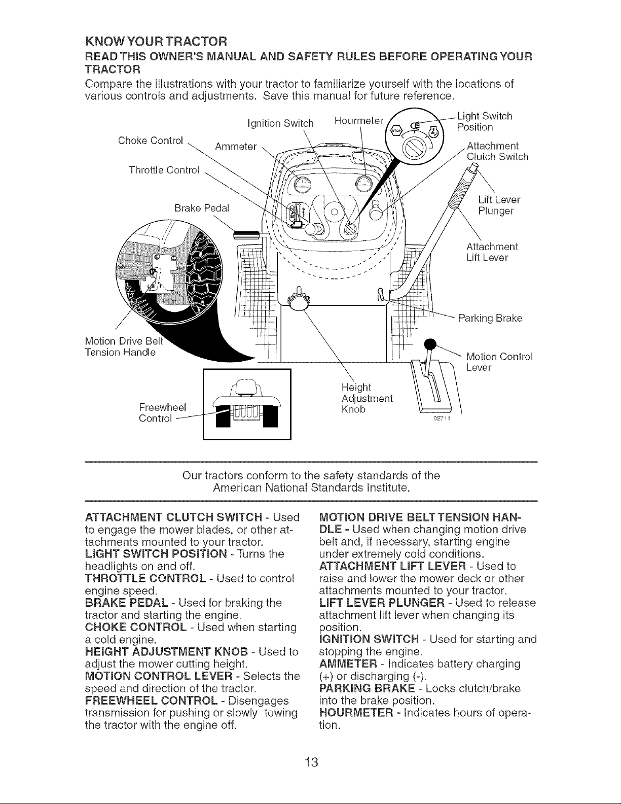
KNOW YOUR TRACTOR
READ THINS OWNER'S MANUAL AND SAFETY RULES BEFORE OPERATmNG YOUR
TRACTOR
Compare the illustrations with your tractor to familiarize yourself with the locations of
various controls and adjustments. Save this manual for future reference.
ignition Switch Hourmeter iht Switch
Position
Ammeter Attachment
Switch
Lift Lever
Brake Pedal Plunger
Attachment
Lift Lever
Motion Drive Bell
Tension Handle
Freewheel
Control
Height
Adjustment
Knob
02711
Parking Brake
Motion Control
Lever
Our tractors conform to the safety standards of the
American National Standards Institute.
ATTACHMENT CLUTCH SWmTCH - Used
to engage the mower blades, or other at-
tachments mounted to your tractor.
UGHT SWmTCH POSmTmON - Turns the
headlights on and off.
THROTTLE CONTROL - Used to control
engine speed.
BRAKE PEDAL - Used for braking the
tractor and starting the engine.
CHOKE CONTROL - Used when starting
a cold engine.
HEmGHT ADJUSTMENT KNOB - Used to
adjust the mower cutting height.
MOTION CONTROL LEVER - Selects the
speed and direction of the tractor.
FREEWHEEL CONTROL - Disengages
transmission for pushing or slowly towing
the tractor with the engine off.
MOTmON DRmVE BELTTENSmON HAN-
DLE - Used when changing motion drive
belt and, if necessary, starting engine
under extremely cold conditions.
ATTACHMENT UFT LEVER - Used to
raise and lower the mower deck or other
attachments mounted to your tractor.
UFT LEVER PLUNGER - Used to release
attachment lift lever when changing its
position.
mGNmTmONSWmTCH - Used for starting and
stopping the engine.
AMMETER - Indicates battery charging
(+) or discharging (-).
PARKmNG BRAKE - Locks clutch/brake
into the brake position.
HOUR_,_ETER - Indicates hours of opera-
tion.
13
SAFETYGLASSES
The operation of any tractor can result in foreign objects thrown into
the eyes, which can result in severe eye damage. Always wear safety
glasses or eye shields while operating your tractor or performing any
adjustments or repairs. We recommend standard safety glasses or a
wide vision safety mask worn over spectacles.
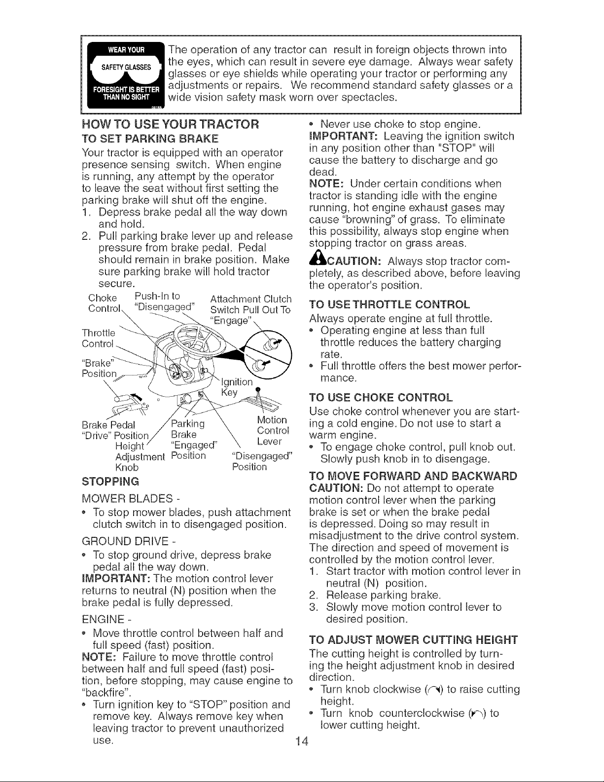
HOW TO USE YOUR TRACTOR
TO SET PARKmNG BRAKE
Your tractor is equipped with an operator
presence sensing switch. When engine
is running, any attempt by the operator
to leave the seat without first setting the
parking brake will shut off the engine.
1. Depress brake pedal all the way down
and hold.
2. Pull parking brake lever up and release
pressure from brake pedal. Pedal
should remain in brake position. Make
sure parking brake will hold tractor
secure.
Choke Pushqn to Attachment CUutch
"Disengaged" Switch Pull Out To
Throttb
Position
\
Brake Pedal Sarking Motion
"Drive" Position Brake Control
Height "Engaged" Lever
Adjustment Position "Disengaged"
Knob Position
STOPPmNG
MOWER BLADES =
To stop mower blades, push attachment
clutch switch in to disengaged position.
GROUND DRIVE =
• To stop ground drive, depress brake
pedal all the way down.
mMPORTANT: The motion control lever
returns to neutral (N) position when the
brake pedal is fully depressed.
ENGINE =
• Move throttle control between half and
full speed (fast) position.
NOTE: Failure to move throttle control
between half and full speed (fast) posi=
tion, before stopping, may cause engine to
"backfire".
Turn ignition key to "STOP" position and
remove key. Always remove key when
leaving tractor to prevent unauthorized
use.
@
14
• Never use choke to stop engine.
mMPORTANT: Leaving the ignition switch
in any position other than "STOP" will
cause the battery to discharge and go
dead.
NOTE: Under certain conditions when
tractor is standing idle with the engine
running, hot engine exhaust gases may
cause "browning" of grass. To eliminate
this possibility, always stop engine when
stopping tractor on grass areas.
,_ICAUTmON: Always stop tractor com=
pletely, as described above, before leaving
the operator's position.
TO USE THROTTLE CONTROL
Always operate engine at full throttle.
• Operating engine at less than full
throttle reduces the battery charging
rate.
Full throttle offers the best mower perfor=
mance.
TO USE CHOKE CONTROL
Use choke control whenever you are start=
ing a cold engine. Do not use to start a
warm engine.
• To engage choke control, putl knob out.
Slowly push knob in to disengage.
TO MOVE FORWARD AND BACKWARD
CAUTmON: Do not attempt to operate
motion control lever when the parking
brake is set or when the brake pedal
is depressed. Doing so may result in
misadjustment to the drive control system.
The direction and speed of movement is
controlled by the motion control lever.
1. Start tractor with motion control lever in
neutral (N) position.
2. Release parking brake.
3. Slowly move motion control lever to
desired position.
TO ADJUST MOWER CUTTING HEIGHT
The cutting height is controlled by turn=
ing the height adjustment knob in desired
direction.
• Turn knob clockwise (_) to raise cutting
height.
Turn knob counterclockwise (_) to
lower cutting height.
The cutting heightrangeis approximately
1-1/2"to 4-1/2". The heightsare mea-
sured from the ground to the bladetip with
the engine not running. These heights
are approximateand may vary depending
uponsoil conditions,heightof grass and
types of grass being mowed.
The averagelawn should be cut to
approximately2-1/2 inches during the
cool season and to over 3 inchesduring
hot months. For healthierand better
looking lawns,mowoften and after
moderategrowth.
For bestcutting performance,grassover
6 inchesin heightshould be mowed
twice. Makethe first cut relativelyhigh;
the secondto desiredheight.
TO ADJUST GAUGEWHEELS
Gaugewheels are properlyadjusted
when they are slightlyoff the groundwhen
moweris at the desiredcutting height in
operatingposition.Gaugewheels then
keepthe deck in properposition to help
preventscalpingin mostterrainconditions.
NOTE:Be sure tractor is on a flat level
surface.
1. Lowermowerand adjust mowerto de-
sired cutting height(See"TOADJUST
MOWERCUTTINGHEIGHT"in this
sectionof manual).
2. Removeretainerspring and clevis pin
whichsecureeach gaugewheel bar.
3. Lowergaugewheels to ground.Raise
gaugewheels sJightlyto aJignholes
in bracketand gaugewheel bar and
insert clevis pin.Gauge wheelsshould
be slightly off the ground.
4. Replaceretainerspring into clevis pin.
5. Be sure all gaugewheels are in the
same setting.
iMPORTANT:Be sure to readjustgauge
wheels if you change the cutting height
of the mowerdeck.
Retainer
Spring
Clevis
,. :// Pin
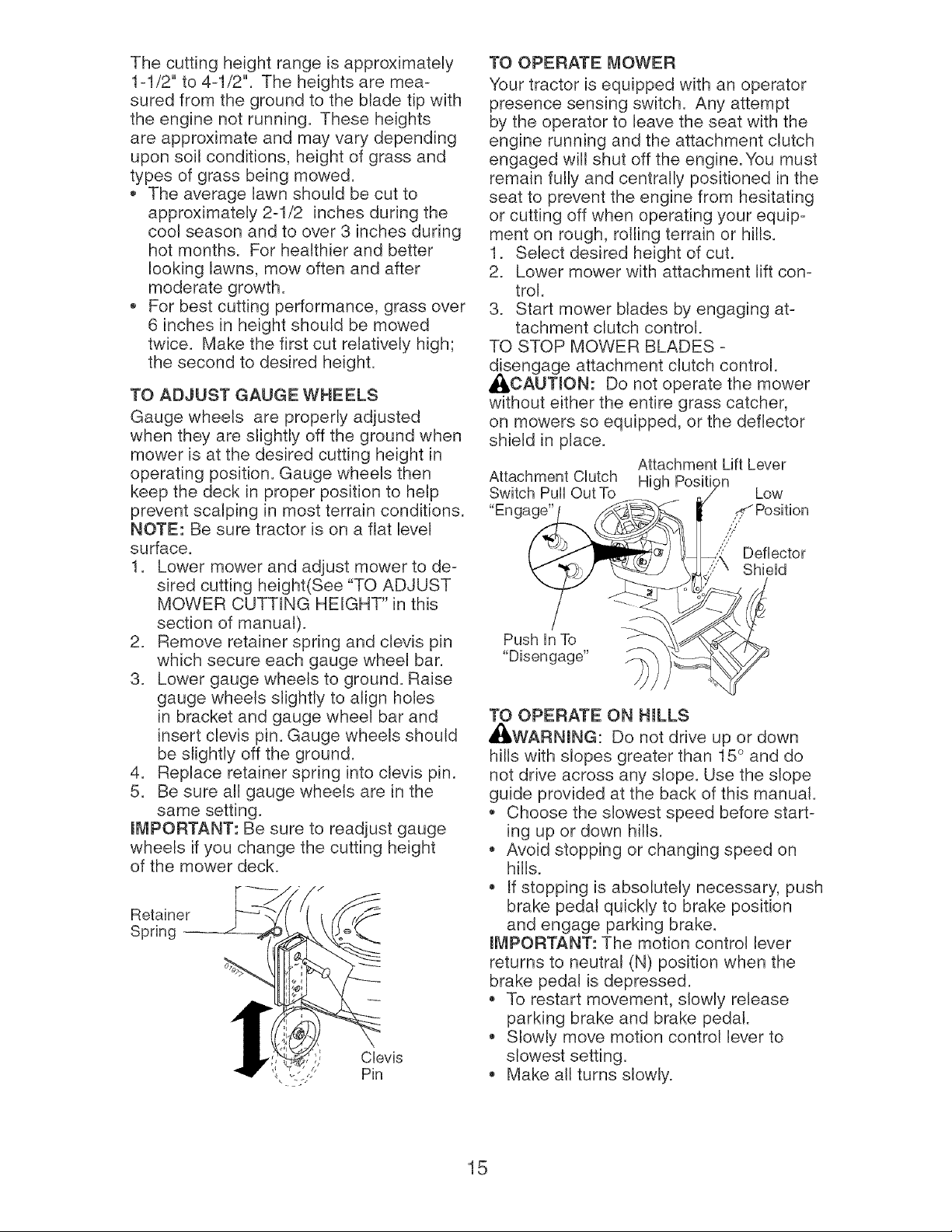
TO OPERATE MOWER
Your tractor is equipped with an operator
presence sensing switch. Any attempt
by the operator to leave the seat with the
engine running and the attachment clutch
engaged will shut off the engine. You must
remain fully and centrally positioned in the
seat to prevent the engine from hesitating
or cutting off when operating your equip-
ment on rough, roiling terrain or hills.
1. Select desired height of cut.
2. Lower mower with attachment lift con-
trol.
3. Start mower blades by engaging at-
tachment clutch control.
TO STOP MOWER BLADES -
disengage attachment clutch control.
_CAUTJON: Do not operate the mower
without either the entire grass catcher,
on mowers so equipped, or the deflector
shield in place.
Attachment Lift Lever
Attachment Clutch High Position
Switch Pull Out To / Low
"Enga_ _ Position
( _ _/_'_e_J _ _"_" Deflector
',"1 "_, / \'---_ / \ <,""\ Shield
o I /
Push In To ,, _'"X-,_/_-X_J_,
"Disengage" )_ _
TO OPERATE ON HILLS
_L, WARNJNG: Do not drive up or down
hills with slopes greater than 15 ° and do
not drive across any slope. Use the slope
guide provided at the back of this manual.
,_ Choose the slowest speed before start-
ing up or down hills.
,, Avoid stopping or changing speed on
hills.
,, If stopping is absoluteJy necessary, push
brake pedal quickly to brake position
and engage parking brake.
iMPORTANT: The motion control lever
returns to neutral (N) position when the
brake pedal is depressed.
To restart movement, slowly release
parking brake and brake pedal.
Slowly move motion control lever to
slowest setting.
Make all turns slowly.
15
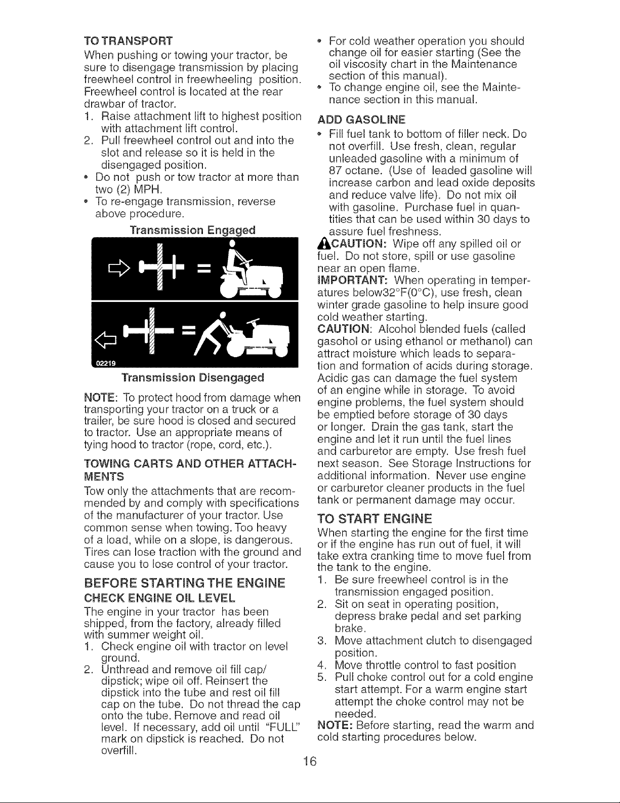
TO TRANSPORT
When pushing or towing your tractor, be
sure to disengage transmission by placing
freewheel control in freewheeling position.
Freewheel control is located at the rear
drawbar of tractor.
1. Raise attachment lift to highest position
with attachment lift control.
2. Pull freewheel control out and into the
slot and release so it is held in the
disengaged position.
Do not push or tow tractor at more than
two (2) MPH.
To re-engage transmission, reverse
above procedure.
Transmission Engaged
Transmission Disengaged
NOTE: To protect hood from damage when
transporting your tractor on a truck or a
trailer, be sure hood is closed and secured
to tractor. Use an appropriate means of
tying hood to tractor (rope, cord, etc.).
TOWmNG CARTS AND OTHER ATTACH-
MENTS
Tow only the attachments that are recom-
mended by and comply with specifications
of the manufacturer of your tractor. Use
common sense when towing. Too heavy
of a load, while on a slope, is dangerous.
Tires can lose traction with the ground and
cause you to lose control of your tractor.
BEFORE STARTmNG THE ENGmNE
CHECK ENGmNE OraL LEVEL
The engine in your tractor has been
shipped, from the factory, already filled
with summer weight oil.
1. Check engine oil with tractor on level
ground.
2. Unthread and remove oil fill cap/
dipstick; wipe oil off. Reinsert the
dipstick into the tube and rest oil fill
cap on the tube. Do not thread the cap
onto the tube. Remove and read oil
level. If necessary, add oil until "FULL:'
mark on dipstick is reached. Do not
overfill.
For cold weather operation you should
change oil for easier starting (See the
oil viscosity chart in the Maintenance
section of this manual).
To change engine oil, see the Mainte-
nance section in this manual.
ADD GASOUNE
Fill fuel tank to bottom of filler neck. Do
not overfill. Use fresh, clean, regular
unleaded gasoline with a minimum of
87 octane. (Use of leaded gasoline will
increase carbon and lead oxide deposits
and reduce valve life). Do not mix oil
with gasoline. Purchase fuel in quan-
tities that can be used within 30 days to
assure fuel freshness.
_:_CAUTmON: Wipe off any spilled oil or
fuel. Do not store, spill or use gasoline
near an open flame.
mMPORTANT: When operating in temper-
atures below32°F(0°C), use fresh, clean
winter grade gasoline to help insure good
cold weather starting.
CAUTmON: Alcohol blended fuels (called
gasohol or using ethanol or methanol) can
attract moisture which leads to separa-
tion and formation of acids during storage.
Acidic gas can damage the fuel system
of an engine while in storage. To avoid
engine problems, the fuel system should
be emptied before storage of 30 days
or longer. Drain the gas tank, start the
engine and let it run until the fuel lines
and carburetor are empty. Use fresh fuel
next season. See Storage Instructions for
additional information. Never use engine
or carburetor cleaner products in the fuel
tank or permanent damage may occur.
TO START ENGINE
When starting the engine for the first time
or if the engine has run out of fuel, it will
take extra cranking time to move fuel from
the tank to the engine.
1. Be sure freewheel control is in the
transmission engaged position.
2. Sit on seat in operating position,
depress brake pedal and set parking
brake.
3. Move attachment clutch to disengaged
position.
4. Move throttle control to fast position
5. Pull choke control out for a cold engine
start attempt. For a warm engine start
attempt the choke control may not be
needed.
NOTE: Before starting, read the warm and
cold starting procedures below.
16
6. Insert key into ignition and turn key
clockwise to start position and release
key as soon as engine starts. Do
not run starter continuously for more
than fifteen seconds per minute. If the
engine does not start after several
attempts, push choke control in, wait
a few minutes and try again. If engine
still does not start, pull the choke con-
trol out and retry.
WARM WEATHER STARTING (50 ° F and
above)
7. When engine starts, slowly push choke
control in until the engine begins to
run smoothly. If the engine starts to
run roughly, pull the choke control out
slightly for a few seconds and then
continue to push the control in slowly.
The attachments and ground drive can
now be used. If the engine does not
accept the load, restart the engine and
allow it to warm up for one minute using
the choke as described above.
COLD WEATHER STARTING (50 ° F and
below)
7. When engine starts, slowly push choke
control in until the engine begins to run
smoothly. Continue to push the choke
control in small steps allowing the en-
gine to accept small changes in speed
and load, until the choke control is fully
in. If the engine starts to run roughly,
pull the choke control out slightly for a
few seconds and then continue to push
the control in slowly. This may require
an engine warm-up period from several
seconds to several minutes, depending
on the temperature.
NOTE: In extreme cold conditions, if
engine will not start you may need to dis-
engage the motion drive belt as follows:
1. Be sure parking brake is engaged.
2. Remove retainer spring from the drive
belt tension handle to relieve belt ten-
sion.
3. Start engine and allow it to warm up for
three (3) minutes.
4. Shut-off engine and engage parking
brake.
5. Engage drive belt tension handle and
replace the retainer spring.
AUTOMATIC TRANSMISSION WARM UP
Before driving the unit in cold weather,
the transmission should be warmed up as
follows:
1. Be sure the tractor is on level ground.
2. Place the motion control lever in
neutral. Release the parking brake and
let the brake slowly return to operating
position.
3. Allow one minute for transmission to
warm up. This can be done during the
engine warm up period.
The attachments can be used during
the engine warm-up period after the
transmission has been warmed up and
may require the choke control be pulled
out slightly.
NOTE: If at a high altitude (above 3000
feet) or in cold temperatures (below 32 F)
the carburetor fuel mixture may need to
be adjusted for best engine performance
(see "TO ADJUST CARBURETOR" in the
Service and Adjustments section of this
manual).
PURGE TRANSMmSSION
_ICAUTmON: Never engage or dis-
engage freewheel lever while the engine
is running.
To ensure proper operation and per-
formance, it is recommended that the
transmission be purged before operating
tractor for the first time. This procedure will
remove any trapped air inside the trans-
mission which may have developed during
shipping of your tractor.
IMPORTANT: Should your transmission
require removal for service or replace-
ment, it should be purged after reinstall-
ation before operating the tractor.
1. Place tractor safely on level surface
with engine off and parking brake set.
2. Disengage transmission by plac-
ing freewheel control in disengaged
position (See "TO TRANSPORT" in this
section of manual).
3. Sitting in the tractor seat, start engine.
After the engine is running, move
throttle control to slow position. Disen-
gage parking brake.
4. Move motion control lever to full
forward position and hold for five (5)
seconds. Move lever to full reverse
position and hold for five (5) seconds.
Repeat this procedure three (3) times.
NOTE: During this step there will be no
movement of drive wheels. The air is being
removed from hydraulic drive system.
5. Move motion control lever to neutral
(N) position. Shutoff engine and set
parking brake.
6. Engage transmission by placing free-
wheel control in engaged position (See
"TO TRANSPORT" in this section of
manual).
17
7. Sitting in the tractor seat, start engine.
After the engine is running, move
throttle control to half (1/2) speed.
Disengage parking brake.
8. Slowly move motion control lever for-
ward, after the tractor moves approxi-
mately five (5) feet, slowly move motion
control lever to reverse position. After
the tractor moves approximately five
(5) feet return the motion control lever
to the neutral (N) position. Repeat this
procedure with the motion control lever
three (3) times.
Your transmission is now purged and now
ready for normal operation.
MOWING TIPS
,, Tire chains cannot be used when the
mower housing is attached to tractor.
,, Mower should be properly leveled for
best mowing performance. See "TO
LEVEL MOWER HOUSING" in the
Service and Adjustments section of this
manual.
The left hand side of mower should be
used for trimming.
Drive so that clippings are discharged
onto the area that has already been
cut. Have the cut area to the right of
the tractor. This will result in a more
even distribution of clippings and more
uniform cutting.
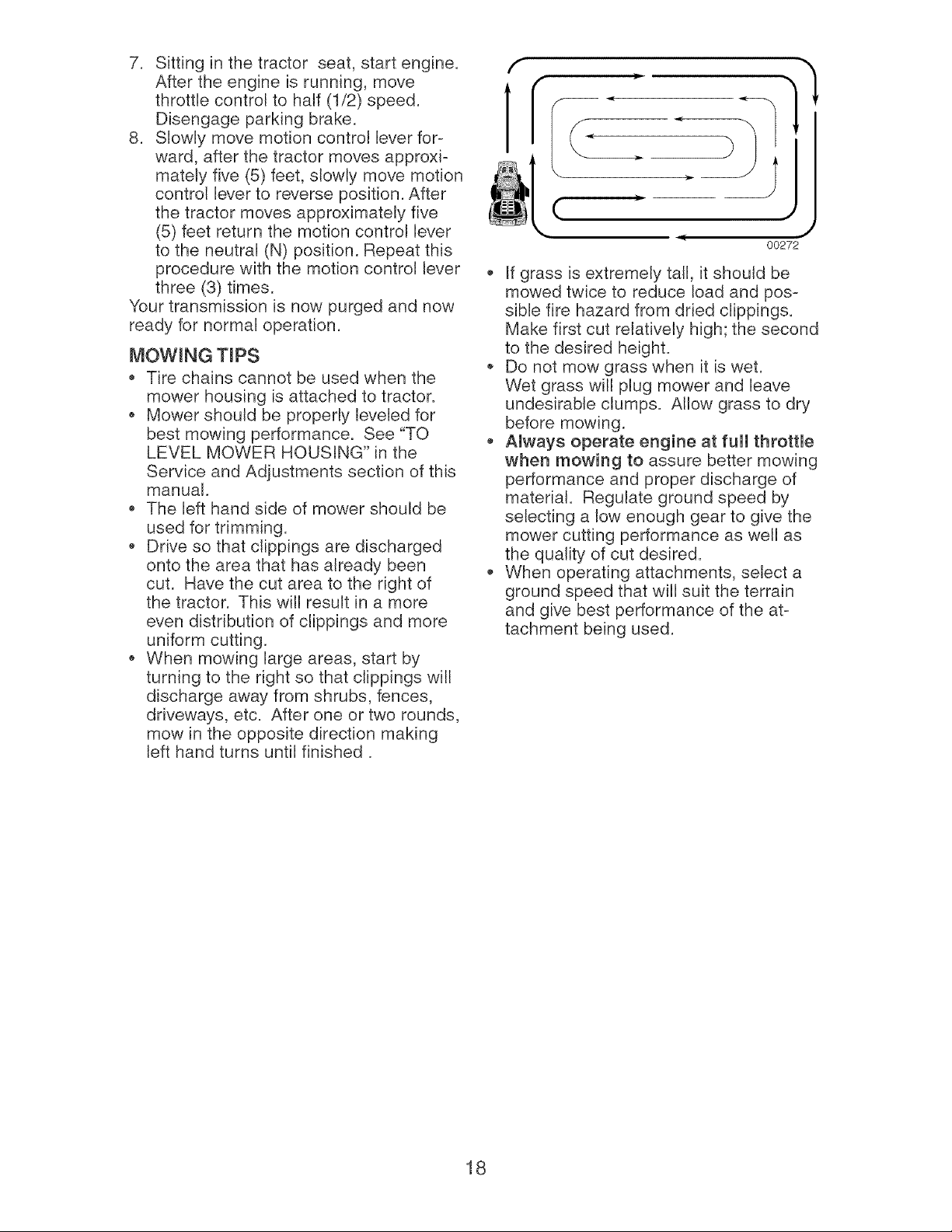
When mowing large areas, start by
turning to the right so that clippings will
discharge away from shrubs, fences,
driveways, etc. After one or two rounds,
mow in the opposite direction making
left hand turns until finished.
f
r
(
G_
,J
, J
00272
If grass is extremely tall, it should be
mowed twice to reduce load and pos-
sible fire hazard from dried clippings.
Make first cut relatively high; the second
to the desired height.
Do not mow grass when it is wet.
Wet grass will plug mower and leave
undesirable clumps. Allow grass to dry
before mowing.
Always operate engine at full throttle
when mowing to assure better mowing
performance and proper discharge of
material. Regulate ground speed by
selecting a low enough gear to give the
mower cutting performance as well as
the quality of cut desired.
• When operating attachments, select a
ground speed that will suit the terrain
and give best performance of the at-
tachment being used.
18
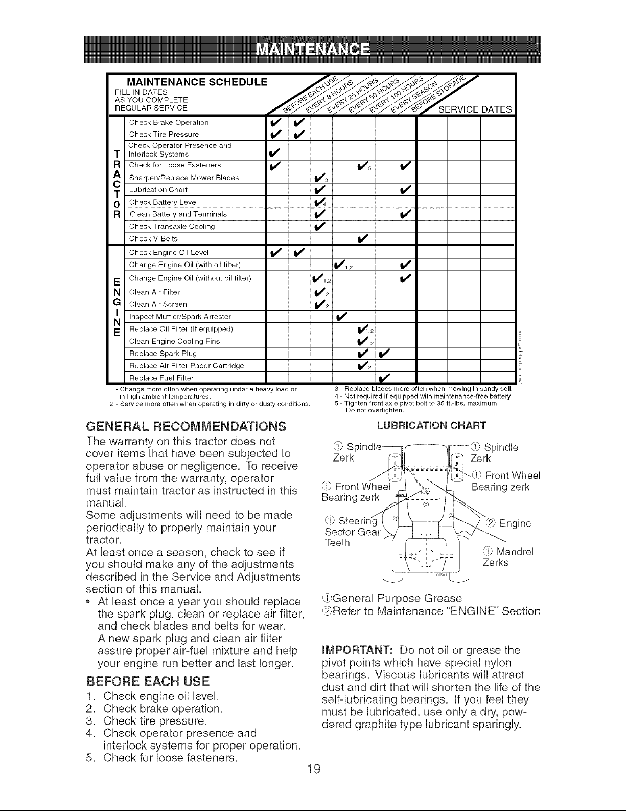
MAINTENANCESCHEDULE
F,LL,=OATES
ASYOOOO=P'ETEf ZE=V'OE
REGULAR SERVICE DATES
Check Brake Operation _
Check Tire Pressure
Check Operator Presence and
T Interlock Systems
R Check for Loose Fasteners if 1_#'5
Sharpen/Replace Mower Blades 1_#'3
T Lubrication Chart if I1_
O Check Battery Level _4
R Clean Battery and Terminals if if
Check Transaxle Cooling
Check V-Belts I_
Check Engine Oil Level _
Change Engine Oil (with oil filter) 11_,,2
E Change Engine Oil (without oil filter) _1,_ if
N Clean Air Filter 1_#'2
G Clean Air Screen 1_2
NI Inspect Muffler/Spark
Arrester
E Replace Oil Filter (If equipped) _,2
Clean Engine Cooling Fins if 2
Replace Spark Plug I_ if
Replace Air Filter Paper Cartridge lI_2
Replace Fuel Filter _#_
1 - Change more often when operating under a heavy load or
in high ambient temperatures.
2 - Service more often when operating in dirty or dusty conditions.
3 - Replace blades more often when mowing in sandy soil.
4 - Not required if equipped with maintenance-free battery.
5 - Tighten front axle pivot bolt to 35 ft.-Ibs, maximum.
Do not overtighten.
GENERAL RECOMMENDATIONS
The warranty on this tractor does not
cover items that have been subjected to
operator abuse or negligence. To receive
full value from the warranty, operator
must maintain tractor as instructed in this
manual.
Some adjustments will need to be made
periodically to properly maintain your
tractor.
At least once a season, check to see if
you should make any of the adjustments
described in the Service and Adjustments
section of this manual.
At least once a year you should replace
the spark plug, clean or replace air filter,
and check blades and belts for wear.
A new spark plug and clean air filter
assure proper air-fuel mixture and help
your engine run better and last longer.
BEFORE EACH USE
1. Check engine oil level.
2. Check brake operation.
3. Check tire pressure.
4. Check operator presence and
interlock systems for proper operation.
5. Check for loose fasteners.
LUBRICATION CHART
(i7 SI Spindle
Zerk Zerk
(i7 Front Wheel
Bearing zerk
Front Wheel
Bearing zerk
(i7 Engine
Sector Gear
Teeth
(i7 Mandrel
Zerks
(0General Purpose Grease
@Refer to Maintenance "ENGINE" Section
IMPORTANT: Do not oil or grease the
pivot points which have special nylon
bearings. Viscous lubricants will attract
dust and dirt that will shorten the life of the
self-lubricating bearings. If you feel they
must be lubricated, use only a dry, pow-
dered graphite type lubricant sparingly.
19
TRACTOR
Always observe safety rules when per-
forming any maintenance.
BRAKE OPERATmON
If tractor requires more than six (6) feet
stopping distance at high speed in highest
gear, then brake must be adjusted. (See
"TO ADJUST BRAKE" in the Service and
Adjustments section of this manual).
TmRES
Maintain proper air pressure in all tires
(See "PRODUCT SPECIFICATIONS"
section of this manual).
* Keep tires free of gasoline, oil, or insect
control chemicals which can harm rub-
ber.
Avoid stumps, stones, deep ruts, sharp
objects and other hazards that may
cause tire damage.
NOTE: To seal tire punctures and prevent
flat tires due to slow leaks, tire sealant
may be purchased from your local parts
dealer. Tire sealant also prevents tire dry
rot and corrosion.
OPERATOR PRESENCE SYSTEM
Be sure operator presence and interlock
systems are working properly. If your trac-
tor does not function as described, repair
the problem immediately.
The engine should not start unless
the brake pedal is fully depressed and
attachement clutch control is in the
disengaged position.
When the engine is running, any at-
tempt by the operator to leave the seat
without first setting the parking brake
should shut off the engine.
* When the engine is running and the
attachment clutch is engaged, any at-
tempt by the operator to leave the seat
should shut off the engine.
The attachment clutch should never op-
erate unless the operator is in the seat.
BLADE CARE
For best results mower blades must be kept
sharp. Replace bent or damaged blades.
BLADE REMOVAL
1. Raise mower to highest position to al-
low access to blades.
NOTE: Protect your hands with gloves
and/or wrap blade with heavy cloth.
2. Remove blade bolt by turning counter-
clockwise.
3. Install new or resharpened blade with
stamped "THIS SIDE UP" facing deck
and mandrel assembly.
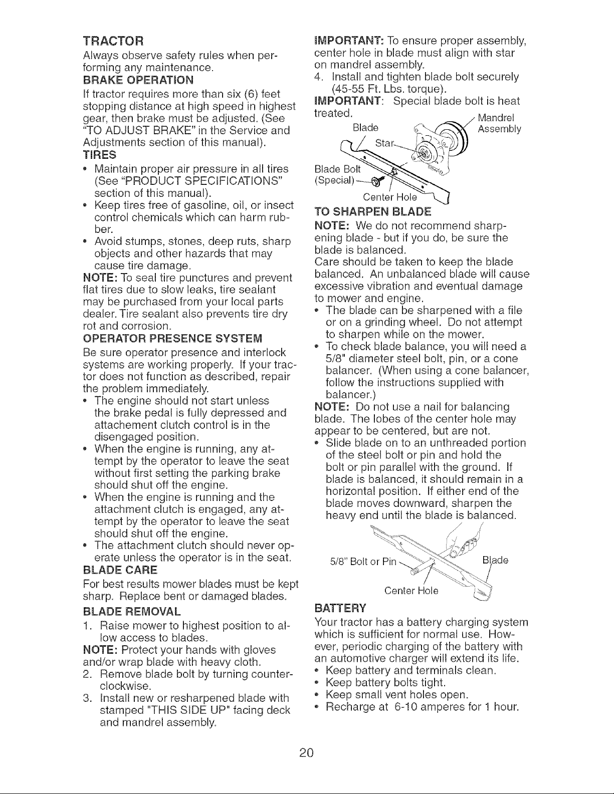
mMPORTANT: To ensure proper assembly,
center hole in blade must align with star
on mandrel assembly.
4. Install and tighten blade bolt securely
(45-55 Ft. Lbs. torque).
mMPORTANT: Special blade bolt is heat
treated. MandreU
B,ade f__ Assembly
_'_Sta r-__.._i_'_._ )
Center HoUe --L..J
TO SHARPEN BLADE
NOTE: We do not recommend sharp-
ening blade - but if you do, be sure the
blade is balanced.
Care should be taken to keep the blade
balanced. An unbalanced blade will cause
excessive vibration and eventual damage
to mower and engine.
* The blade can be sharpened with a file
or on a grinding wheel. Do not attempt
to sharpen while on the mower.
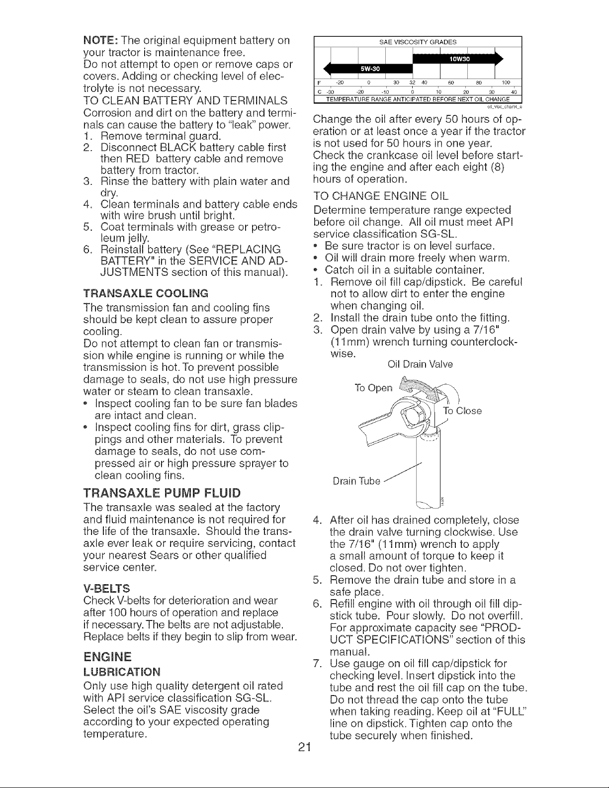
To check blade balance, you will need a
5/8" diameter steel bolt, pin, or a cone
balancer. (When using a cone balancer,
follow the instructions supplied with
balancer.)
NOTE: Do not use a nail for balancing
blade. The lobes of the center hole may
appear to be centered, but are not.
* Slide blade on to an unthreaded portion
of the steel bolt or pin and hold the
bolt or pin parallel with the ground. If
blade is balanced, it should remain in a
horizontal position. If either end of the
blade moves downward, sharpen the
heavy end until the blade is balanced.
/ /
5/8" Bolt ade
Center Hole
BATTERY
Your tractor has a battery charging system
which is sufficient for normal use. How-
ever, periodic charging of the battery with
an automotive charger will extend its life.
* Keep battery and terminals clean.
Keep battery bolts tight.
* Keep small vent holes open.
Recharge at 6-10 amperes for 1 hour.
20
NOTE: The original equipment battery on
your tractor is maintenance free.
Do not attempt to open or remove caps or
covers. Adding or checking level of elec-
trolyte is not necessary.
TO CLEAN BATTERY AND TERMINALS
Corrosion and dirt on the battery and termi-
nals can cause the battery to "leak" power.
1. Remove terminal guard.
2. Disconnect BLACK battery cable first
then RED battery cable and remove
battery from tractor.
3. Rinse the battery with plain water and
dry.
4. Clean terminals and battery cable ends
with wire brush until bright.
5. Coat terminals with grease or petro-
leum jelly.
6. Reinstall battery (See "REPLACING
BATTERY"" in the SERVICE AND AD-
JUSTMENTS section of this manual).
TRANSAXLE COOUNG
The transmission fan and cooling fins
should be kept clean to assure proper
cooling.
Do not attempt to clean fan or transmis-
sion while engine is running or while the
transmission is hot. To prevent possible
damage to seals, do not use high pressure
water or steam to clean transaxb.
Inspect cooling fan to be sure fan blades
are intact and clean.
Inspect cooling fins for dirt, grass clip-
pings and other materials. To prevent
damage to seals, do not use com-
pressed air or high pressure sprayer to
clean cooling fins.
TRANSAXLE PUMP FLUID
The transaxb was sealed at the factory
and fluid maintenance is not required for
the life of the transaxb. Should the trans-
axle ever leak or require servicing, contact
your nearest Sears or other qualified
service center.
V-BELTS
Check V-belts for deterioration and wear
after 100 hours of operation and replace
if necessary. The belts are not adjustable.
Replace belts if they begin to slip from wear.
LUBRICATION
Only use high quality detergent oil rated
with API service classification SG-SL
Select the oil's SAE viscosity grade
according to your expected operating
temperature.
21
SAEV,SOOS,T GRAOES
-20 0 30 32 40 60 80 100
-s'o -2'o -1_ 8 /o _o 3o 4'o
TEMPERATURE RANGE ANTICIPATED BEFORE NEXT OIL CHANGE
oil viscchar_4 e
Change the oil after every 50 hours of op-
eration or at least once a year if the tractor
is not used for 50 hours in one year.
Check the crankcase oil level before start-
ing the engine and after each eight (8)
hours of operation.
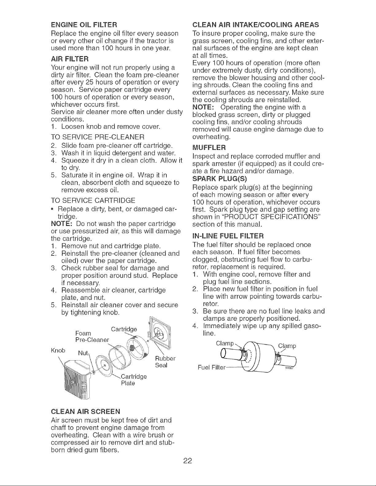
TO CHANGE ENGINE OIL
Determine temperature range expected
before oil change. All oil must meet API
service classification SG-SL
Be sure tractor is on level surface.
Oil will drain more freely when warm.
Catch oil in a suitable container.
1. Remove oil fill cap/dipstick. Be careful
not to allow dirt to enter the engine
when changing oil.
2. Install the drain tube onto the fitting.
3. Open drain valve by using a 7/16""
(11 mm) wrench turning counterclock-
wise.
Oil Drain Valve
To Open
To Close
Drain Tube
4. After oil has drained compbtely, close
the drain valve turning clockwise. Use
the 7/16"" (11 mm) wrench to apply
a small amount of torque to keep it
closed. Do not over tighten.
5. Remove the drain tube and store in a
safe place.
6. Refill engine with oil through oil fill dip-
stick tube. Pour slowly. Do not overfill.
For approximate capacity see "PROD-
UCT SPECIFICATIONS" section of this
manual.
7. Use gauge on oil fill cap/dipstick for
checking level. Insert dipstick into the
tube and rest the oil fill cap on the tube.
Do not thread the cap onto the tube
when taking reading. Keep oil at "FULL:'
line on dipstick. Tighten cap onto the
tube securely when finished.
ENGmNEOIL FmLTER
Replacethe engine oil filter every season
or every other oil change if the tractor is
used morethan 100 hoursin one year.
AmRFmLTER
Yourengine will not run properlyusing a
dirty air filter. Clean the foam pre-cleaner
afterevery 25 hoursof operationor every
season. Service paper cartridge every
100 hours of operationor everyseason,
whicheveroccursfirst.
Serviceair cleaner more often under dusty
conditions.
1. Loosen knoband removecover.
TO SERVICEPRE-CLEANER
2. Slidefoam pre-cleaneroff cartridge.
3. Wash it in liquiddetergent and water.
4. Squeezeit dry in a clean cloth. Allow it
to dry.
5. Saturateit in engineoil. Wrap it in
clean, absorbentcloth and squeezeto
removeexcess oil.
TO SERVICECARTRIDGE
* Replace a dirty, bent, or damaged car-
tridge.
NOTE: Do not wash the paper cartridge
or use pressurized air, as this will damage
the cartridge.
1. Remove nut and cartridge plate.
2. Reinstall the pre-cleaner (cleaned and
oiled) over the paper cartridge.
3. Check rubber seat for damage and
proper position around stud. Replace
if necessary.
4. Reassemble air cleaner, cartridge
plate, and nut.
5. Reinstall air cleaner cover and secure
by tightening knob.
Cartrid(
Foam
Pre-Cleaner
--,.
Knob Nut
\ Rubber
SeaU
Cartridge
Plate
CLEAN AmR mNTAKE/COOUNG AREAS
To insure proper cooling, make sure the
grass screen, cooling fins, and other exter-
nal surfaces of the engine are kept clean
at all times.
Every 100 hours of operation (more often
under extremely dusty, dirty conditions),
remove the blower housing and other cool-
ing shrouds. Clean the cooling fins and
external surfaces as necessary. Make sure
the cooling shrouds are reinstalled.
NOTE: Operating the engine with a
blocked grass screen, dirty or plugged
cooling fins, and/or cooling shrouds
removed will cause engine damage due to
overheating.
MUFFLER
Inspect and replace corroded muffler and
spark arrester (if equipped) as it could cre-
ate a fire hazard and/or damage.
SPARK PLUG(S)
Replace spark plug(s) at the beginning
of each mowing season or after every
100 hours of operation, whichever occurs
first. Spark plug type and gap setting are
shown in "PRODUCT SPECIFICATIONS"
section of this manual.
mN-UNE FUEL FmLTER
The fuel filter should be replaced once
each season. If fuel filter becomes
clogged, obstructing fuel flow to carbu-
retor, replacement is required.
1. With engine cool, remove filter and
plug fuel line sections.
2. Place new fuel filter in position in fuel
line with arrow pointing towards carbu-
retor.
3. Be sure there are no fuel line leaks and
clamps are properly positioned.
4. Immediately wipe up any spilled gaso-
line.
Fuel Filter---__
CLEAN AmR SCREEN
Air screen must be kept free of dirt and
chaff to prevent engine damage from
overheating. Clean with a wire brush or
compressed air to remove dirt and stub-
born dried gum fibers.
22
Clean engine, battery, seat, finish, etc.
of all foreign matter.
Keep finished surfaces and wheels free
of all gasoline, oil, etc.
* Protect painted surfaces with auto-
motive type wax.
W]e do not recommend using a garden
hose or pressure washer to clean your
tractor unless the engine and transmis-
sion are covered to keep water out. Water
in engine or transmission will shorten the
useful life of your tractor. Use compressed
air or a leaf blower to remove grass,
leaves and trash from tractor and mower.
WARNmNG: TO AVOmD SERmOUS mNJURY, BEFORE PERFORMmNG ANY SER=
VmCE OR ADJUSTMENTS:
1. Depress brake pedal fully and set parking brake.
2. Place attachment clutch in "DISENGAGED" position.
3. Turn ignition key to "STOP" and remove key.
4. Make sure the blades and all moving parts have completely stopped.
5. Disconnect spark plug wire from spark plug and place wire where it cannot
come in contact with plug.
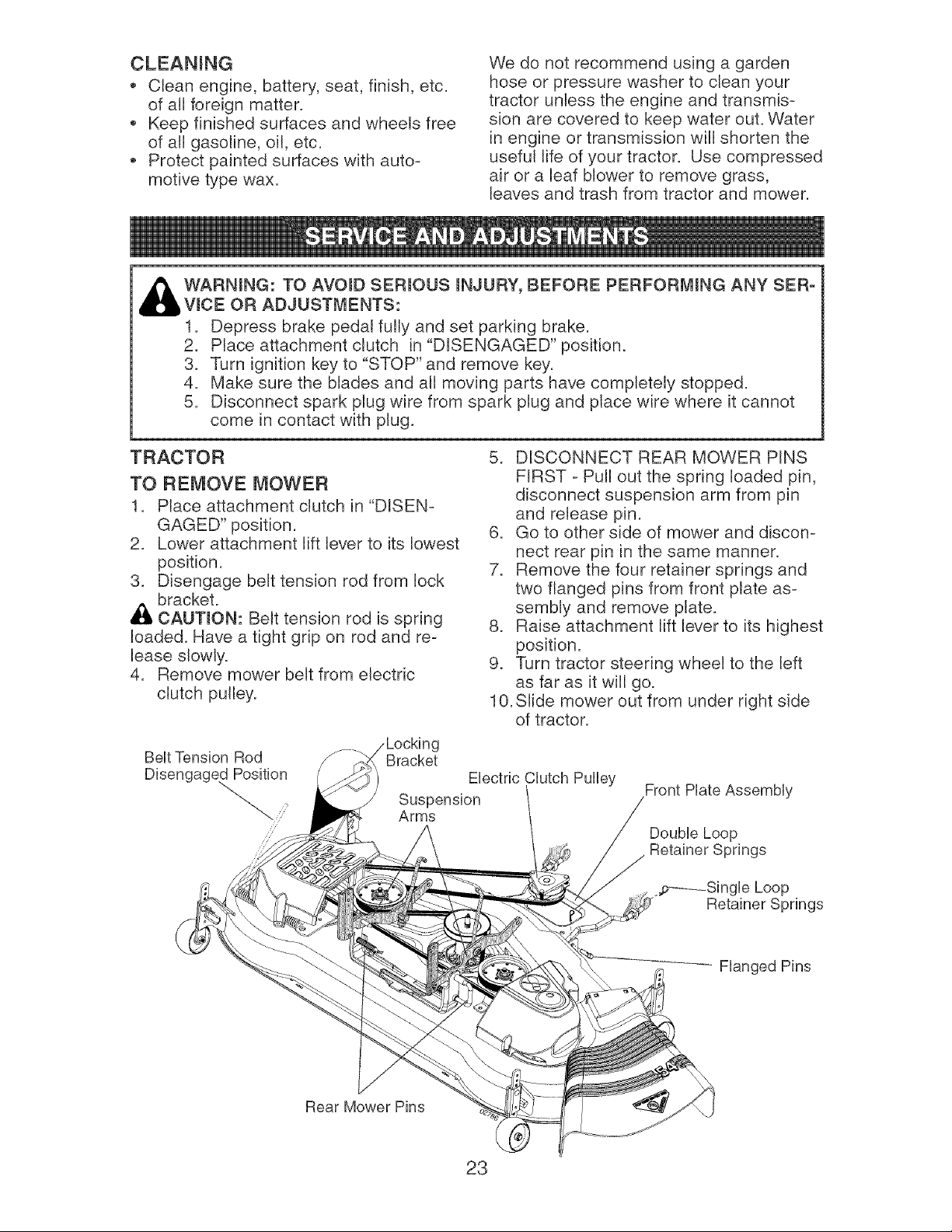
TRACTOR
TO REMOVE MOWER
1. Place attachment clutch in "DISEN-
GAGED" position.
2. Lower attachment lift lever to its lowest
position.
3. Disengage belt tension rod from lock
bracket.
_i, CAUTmON: Belt tension rod is spring
loaded. Have a tight grip on rod and re=
lease slowly.
4. Remove mower belt from electric
clutch pulley.
5. DISCONNECT REAR MOWER PINS
FIRST - Pull out the spring loaded pin,
disconnect suspension arm from pin
and release pin.
6. Go to other side of mower and discon-
nect rear pin in the same manner.
7. Remove the four retainer springs and
two flanged pins from front plate as-
semNy and remove plate.
8. Raise attachment lift lever to its highest
position.
9. Turn tractor steering wheel to the left
as far as it will go.
10. Slide mower out from under right side
of tractor.
BeUtTension Rod Bracket
Ebctric Clutch Pulley
!
Front Plate Assembly
Double Loop
Retainer Springs
,,p-----Single Loop
Retainer Springs
Flanged Pins
Rear Mower Pins
23
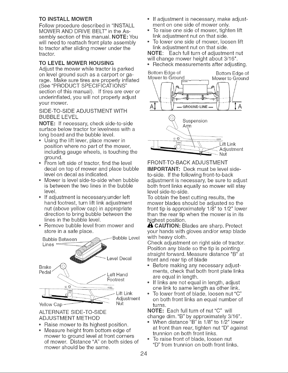
TO mNSTALL MOWER
Follow procedure described in "INSTALL
MOWER AND DRIVE BELT" in the As-
sembly section of this manual. NOTE: You
will need to reattach front plate assembly
to tractor after sliding mower under the
tractor.
TO LEVEL MOWER HOUSING
Adjust the mower while tractor is parked
on level ground such as a carport or ga-
rage. Make sure tires are properly inflated
(See "PRODUCT SPECIFICATIONS"
section of this manual). If tires are over or
underinflated, you will not properly adjust
your mower.
SIDE-TO-SIDE ADJUSTMENT WITH
BUBBLE LEVEL
NOTE: If necessary, check side-to-side
surface below tractor for levelness with a
long board and the bubble level.
Using the lift lever, place mower in
position where no part of the mower,
including gauge wheels, is touching the
ground.
From left side of tractor, find the level
decal on top of mower and place bubble
level on decal as indicated.
Mower is level side-to-side when bubble
is between the two lines in the bubble
level.
If adjustment is necessary, under left
hand footrest, turn lift link adjustment
nut (above yellow cap) in appropriate
direction to bring bubble between the
lines in the bubble level.
Remove bubble level from mower and
store in a safe place.
Lift Link
Nut
ALTERNATE SIDE-TO-SIDE
ADJUSTMENT METHOD
Raise mower to its highest position.
Measure height from bottom edge of
mower to ground level at front corners
of mower. Distance "A" on both sides of
mower should be the same.
If adjustment is necessary, make adjust-
ment on one side of mower only.
To raise one side of mower, tighten lift
link adjustment nut on that side.
To lower one side of mower, loosen lift
link adjustment nut on that side.
NOTE: Each full turn of adjustment nut
will change mower height about 3/16".
Recheck measurements after adjusting.
Bottom Edge of Bottom Edge of
Mower to Ground Mower to Ground
FRONT=TO-BACK ADJUSTMENT
miViPORTANT: Deck must be level side=
to=side. If the following front=to=back
adjustment is necessary, be sure to adjust
both front links equally so mower will stay
level side-to-side.
To obtain the best cutting results, the
mower blades should be adjusted so the
front tip is approximately 1/8" to 1/2" lower
than the rear tip when the mower is in its
,_lghest position.
CAUTION: Blades are sharp. Protect
your hands with gloves and/or wrap blade
with heavy cloth.
Check adjustment on right side of tractor.
Position any blade so the tip is pointing
straight forward. Measure distance "B" at
front and rear tip of blade
,, Before making any necessary adjust=
merits, check that both front plate links
are equal in length.
If links are not equal in length, adjust
one link to same length as other link.
To lower front of blade, loosen nut "C"
on both front links an equal number of
turns.
NOTE: Each full turn of nut "C" will
change dim. "B" by approximately 3/16".
* When distance "B" is 1/8" to 1/2" lower
at front than rear, tighten nut "D" against
trunnion on both front links.
* To raise front of blade, loosen nut
"D" from trunnion on both front links.
24
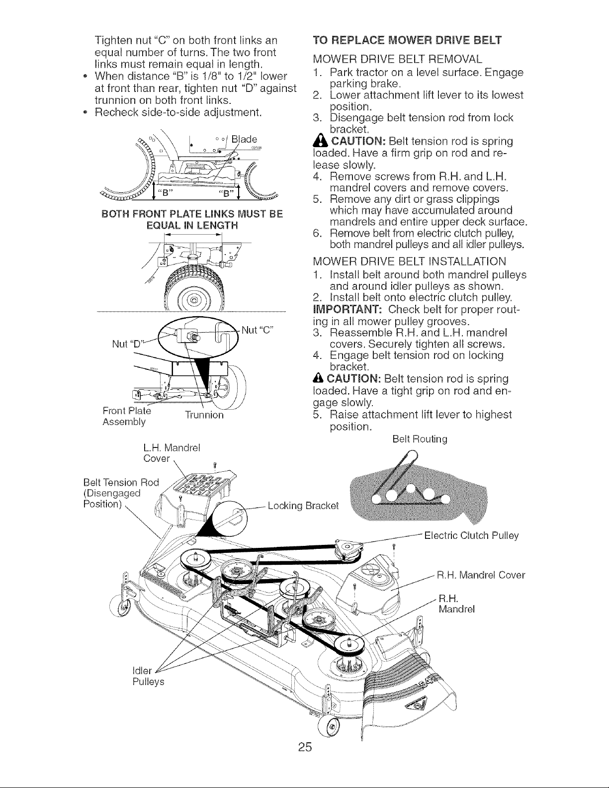
Tighten nut "C" on both front links an
equal number of turns. The two front
links must remain equal in length.
When distance "B" is 1/8" to 1/2" lower
at front than rear, tighten nut "D" against
trunnion on both front links.
Recheck side-to-side adjustment.
BUade
BOTH FRONT PLATE LINKS MUST BE
EQUAL IN LENGTH
Front PUate
AssemMy
Trunnion
LH. Mandrel
Cover
TO REPLACE I_,_OWERDRmVE BELT
MOWER DRIVE BELT REMOVAL
1. Park tractor on a level surface. Engage
parking brake.
2. Lower attachment lift lever to its lowest
position.
3. Disengage belt tension rod from lock
bracket.
,_ CAUTION: Belt tension rod is spring
loaded. Have a firm grip on rod and re-
lease slowly.
4. Remove screws from R.H. and LH.
mandrel covers and remove covers.
5. Remove any dirt or grass clippings
which may have accumulated around
mandrels and entire upper deck surface.
6. Remove belt from electric clutch pulley,
both mandrel pulleys and all idler pulleys.
MOWER DRIVE BELT INSTALLATION
1. Install belt around both mandrel pulleys
and around idler pulleys as shown.
2. Install belt onto electric clutch pulley.
mMPORTANT: Check belt for proper rout-
ing in all mower pulley grooves.
3. Reassemble R.H. and LH. mandrel
covers. Securely tighten all screws.
4. Engage belt tension rod on locking
bracket.
_:_ CAUTmON: Belt tension rod is spring
loaded. Have a tight grip on rod and en-
gage slowly.
5. Raise attachment lift lever to highest
position.
Belt Routing
Belt Tension Rod
(Disengaged
Position) ....... }}:;:;_,
Locking Bracket
Clutch Pulley
Mandrel Cover
Mandrel
Idler
Pulleys
25
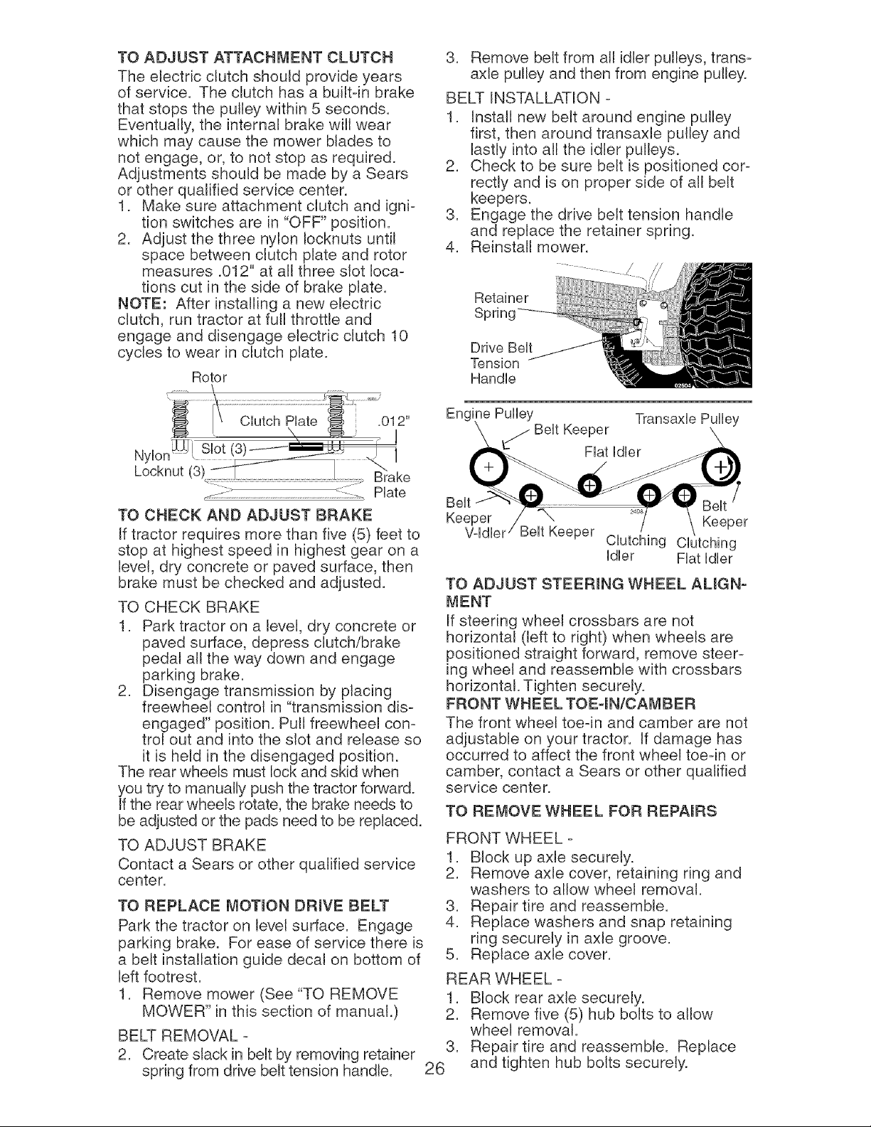
TO ADJUST ATTACHMENT CLUTCH
The electric clutch should provide years
of service. The clutch has a built-in brake
that stops the pulley within 5 seconds.
Eventually, the internal brake will wear
which may cause the mower blades to
not engage, or, to not stop as required.
Adjustments should be made by a Sears
or other qualified service center.
1. Make sure attachment clutch and igni-
tion switches are in "OFF" position.
2. Adjust the three nylon Iocknuts until
space between clutch plate and rotor
measures .012" at all three slot loca-
tions cut in the side of brake plate.
NOTE: After installing a new electric
clutch, run tractor at full throttle and
engage and disengage electric clutch 10
cycles to wear in clutch plate.
Rotor
3. Remove belt from all idler pulleys, trans-
axle pulley and then from engine pulley.
BELT INSTALLATION -
1. Install new belt around engine pulley
first, then around transaxle pulley and
lastly into all the idler pulleys.
2. Check to be sure belt is positioned cor-
rectly and is on proper side of all belt
keepers.
3. Engage the drive belt tension handle
and replace the retainer spring.
4. Reinstall mower.
Retainer
Spring
Drive Belt
Tension
Handle
Engine Pulley
_ Belt Keeper
Fiat Idler
TO CHECK AND ADJUST BRAKE
If tractor requires more than five (5) feet to
stop at highest speed in highest gear on a
level, dry concrete or paved surface, then
brake must be checked and adjusted.
TO CHECK BRAKE
1. Park tractor on a level, dry concrete or
paved surface, depress clutch/brake
pedal all the way down and engage
parking brake.
2. Disengage transmission by placing
freewheel control in "transmission dis-
engaged" position. Pull freewheel con-
trol out and into the slot and release so
it is held in the disengaged position.
The rear wheels must lock and skid when
you try to manually push the tractor forward.
If the rear wheels rotate, the brake needs to
be adjusted or the pads need to be replaced.
TO ADJUST BRAKE
Contact a Sears or other qualified service
center.
TO REPLACE I_4OTION DRmVE BELT
Park the tractor on level surface. Engage
parking brake. For ease of service there is
a belt installation guide decal on bottom of
left footrest.
1. Remove mower (See "TO REMOVE
MOWER" in this section of manual.)
BELT REMOVAL -
2. Create slack in belt by removing retainer
spring from drive belt tension handle.
Belt
Keeper "_x
V-ldler Keeper
Keeper
Clutching Clutching
Idler Fiat Idler
TO ADJUST STEERmNG WHEEL AUGN-
MENT
If steering wheel crossbars are not
horizontal (left to right) when wheels are
positioned straight forward, remove steer-
ing wheel and reassemble with crossbars
horizontal. Tighten securely.
FRONT WHEEL TOE4N/CAMBER
The front 'wheel toe-in and camber are not
adjustable on your tractor. If damage has
occurred to affect the front wheel toe-in or
camber, contact a Sears or other qualified
service center.
TO REMOVE WHEEL FOR REPAmRS
FRONT WHEEL -
1. Block up axle securely.
2. Remove axle cover, retaining ring and
washers to allow wheel removal.
3. Repair tire and reassemble.
4. Replace washers and snap retaining
ring securely in axle groove.
5. Replace axle cover.
REAR WHEEL -
1. Block rear axle securely.
2. Remove five (5) hub bolts to allow
wheel removal.
3. Repair tire and reassemble. Replace
26 and tighten hub bolts securely.
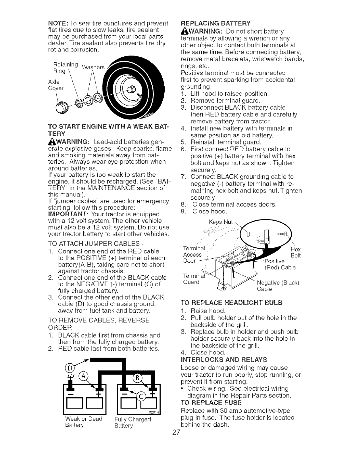
NOTE:Toseattire puncturesand prevent
flat tires due to slow leaks,tire sealant
maybe purchasedfrom your localparts
dealer.Tiresealant also preventstire dry
rot and corrosion.
Retaining Washers
Ring
AxUe
Cover
TO START ENGmNE WroTH A WEAK BAT-
TERY
A(_WARNmNG: Lead-acid batteries gen-
erate explosive gases. Keep sparks, flame
and smoking materials away from bat-
teries. Always wear eye protection when
around batteries.
If your battery is too weak to start the
engine, it should be recharged. (See "BAT-
TERY" in the MAINTENANCE section of
this manual).
If "jumper cables" are used for emergency
starting, follow this procedure:
mMPORTANT: Your tractor is equipped
with a 12 volt system. The other vehicle
must also be a 12 volt system. Do not use
your tractor battery to start other vehicles.
TO ATTACH JUMPER CABLES -
1. Connect one end of the RED cable
to the POSITIVE (+) terminal of each
battery(A-B), taking care not to short
against tractor chassis.
2. Connect one end of the BLACK cable
to the NEGATIVE (-) terminal (C) of
fully charged battery.
3. Connect the other end of the BLACK
cable (D) to good chassis ground,
away from fuel tank and battery.
TO REMOVE CABLES, REVERSE
ORDER -
1. BLACK cable first from chassis and
then from the fully charged battery.
2. RED cable last from both batteries.
02614
Weak or Dead Fully Charged
Battery Battery
REPLACING BATTERY
_I_WARNmNG: Do not short battery
terminals by allowing a wrench or any
other object to contact both terminals at
the same time. Before connecting battery,
remove metal bracelets, wristwatch bands,
rings, etc.
Positive terminal must be connected
first to prevent sparking from accidental
grounding.
1. Lift hood to raised position.
2. Remove terminal guard.
3. Disconnect BLACK battery cable
then RED battery cable and carefully
remove battery from tractor.
4. Install new battery with terminals in
same position as old battery.
5. Reinstall terminal guard.
6. First connect RED battery cable to
positive (+) battery terminal with hex
bolt and keps nut as shown. Tighten
securely.
7. Connect BLACK grounding cable to
negative (-) battery terminal with re-
maining hex bolt and keps nut. Tighten
securely
8. Close terminal access doors.
9. Close hood.
Keps Nut
Terminal ,.--' Hex
Access., Bolt
Door Positive
(Red) Cable
Guard ,gative (Black)
Cable
TO REPLACE HEADUGHT BULB
1. Raise hood.
2. Pull bulb holder out of the hole in the
backside of the grill.
3. Replace bulb in holder and push bulb
holder securely back into the hole in
the backside of the grill.
4. Close hood.
mNTERLOCKS AND RELAYS
Loose or damaged wiring may cause
your tractor to run poorly, stop running, or
prevent it from starting.
,, Check wiring. See electrical wiring
diagram in the Repair Parts section.
TO REPLACE FUSE
Replace with 30 amp automotive-type
plug-in fuse. The fuse holder is located
behind the dash.
27
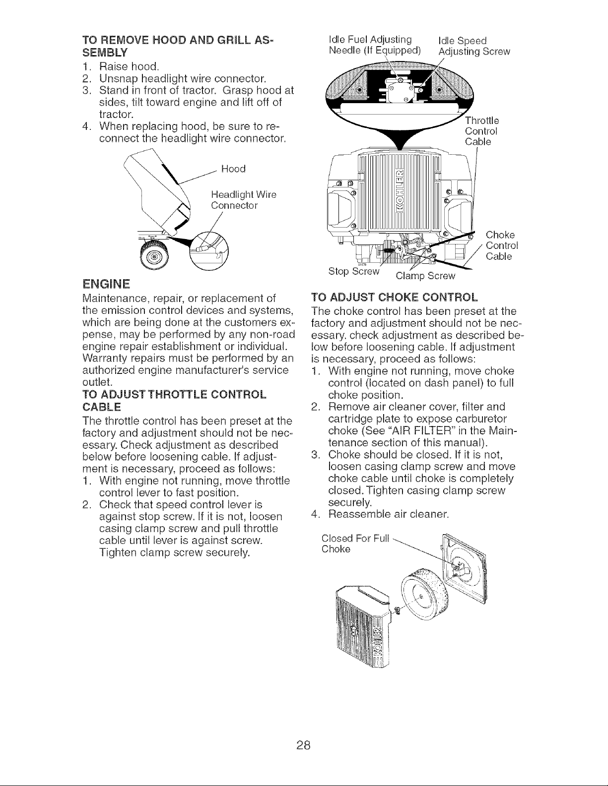
TO REMOVEHOODAND GRILL ASo
SE_,_BLY
1. Rabe hood.
2. Unsnapheadlightwire connector.
3. Stand in front of tractor. Grasphoodat
sides, tilt towardengine and lift off of
tractor.
4. When replacinghood, be sure to re-
connect the headlightwire connector.
Idle Fuel Adjusting
Needle (if E(uipped)
Idle Speed
Ad Screw
Fhrottle
Control
Cable
Hood
Headlight Wire
Connector
Maintenance, repair, or replacement of
the embsion control devices and systems,
which are being done at the customers ex-
pense, may be performed by any non-road
engine repair establishment or individual.
Warranty repairs must be performed by an
authonzed engine manufacturer's servbe
outlet.
TO ADJUST THROTTLE CONTROL
CABLE
The throttle control has been preset at the
factory and adjustment should not be nec-
essary. Check adjustment as described
below before loosening cable. If adjust-
ment is necessary, proceed as follows:
1. With engine not running, move throttle
control lever to fast position.
2. Check that speed control lever is
against stop screw. If it is not, loosen
casing clamp screw and pull throttle
cable until lever is against screw.
Tighten clamp screw securely.
0167_
Stop Screw
Clamp Screw
Choke
Control
Cable
TO ADJUST CHOKE CONTROL
The choke control has been preset at the
factory and adjustment should not be nec-
essary, check adjustment as described be-
low before loosening cable. If adjustment
is necessary, proceed as follows:
1. With engine not running, move choke
control (located on dash panel) to full
choke position.
2. Remove air cleaner cover, filter and
cartridge plate to expose carburetor
choke (See "AIR FILTER" in the Main-
tenance section of this manual).
3. Choke should be closed. If it is not,
loosen casing clamp screw and move
choke cable until choke is completely
closed. Tighten casing clamp screw
securely.
4. Reassemble air cleaner.
Closed For Full
Choke
28
TO ADJUST CARBURETOR
The carburetor has been present at the
factory and adjustment should not be nec-
essary. However, minor adjustment may
be required to compensate for differences
in fuel, temperature, altitude or load. If the
carburetor does need adjustment, proceed
as follows:
In general, turning the adjusting needles
in (clockwise) decreases the supply of
fuel to the engine giving a leaner fuel/air
mixture. Turning the adjusting needles out
(counterclockwise) increases the supply
of fuel to the engine giving a richer fuel/air
mixture.
iMPORTANT: Damage to the needles
and the seats in carburetor may result if
screw is turned in too tight.
PRELIMINARY SETTING -
1. Be sure you have a clean air filter, and
the throttle control cable is adjusted
properly (see "TO ADJUST THROTTLE
CONTROL CABLE" in the Service and
Adjustments section of this manual).
2. With engine off turn idle fuel adjust-
ing needle in (clockwise) closing it
finger tight and then turn out (counter-
clockwise) 1 turn.
FINAL SETTING -
1. Start engine and allow to warm for five
minutes. Make final adjustments with
engine running and shift/motion control
lever in neutral (N) position.
NOTE: The high idle is set at the factory
and cannot be adjusted.
2. Idle speed setting - With throttle control
lever in slow position, engine should
idle at 1750 RPM. If engine idles too
slow or fast, turn idle speed adjusting
screw in or out until correct idle is at-
tained.
3. Idle fuel needle setting - With throttle
control lever in slow position, turn idle
fuel adjusting needle in (clockwise)
until engine speed decreases and then
turn out (counterclockwise) approxi-
mately 3/4 turn to obtain the best low
speed performance.
4. Recheck idle speed. Readjust if neces-
sary.
ACCELERATION TEST -
5. Move throttle controJ lever from slow
to fast position. If engine hesitates or
dies, turn idle fuel adjusting needle out
(counterclockwise) 1/8 turn. Repeat
test and continue to adjust, if neces-
sary, until engine accelerates smoothly.
High speed stop is factory adjusted. Do
not adjust-damage may result.
iMPORTANT: Never tamper with the
engine governor, which is factory set
for proper engine speed. Overspeeding
the engine above the factory high speed
setting can be dangerous. If you think the
engine-governed high speed needs ad-
justing, contact a Sears or other qualified
service center, which has proper equip-
ment and experience to make any neces-
sary adjustments.
29
Immediately prepare your tractor for stor-
age at the end of the season or if the trac-
tor will not be used for 30 days or more.
41_WARNING: Never store the tractor
with gasoline in the tank inside a building
where fumes may reach an open flame
or spark. Allow the engine to cool before
storing in any enclosure.
TRACTOR
Remove mower from tractor for winter
storage. When mower is to be stored for a
period of time, clean it thoroughly, remove
all dirt, grease, leaves, etc. Store in a
clean, dry area.
1. Clean entire tractor (See "CLEANING"
in the Maintenance section of this
manual).
2. Inspect and replace belts, if necessary
(See belt replacement instructions in
the Service and Adjustments section of
this manual).
3. Lubricate as shown in the Maintenance
section of this manual.
4. Be sure that all nuts, bolts and screws
are securely fastened. Inspect moving
parts for damage, breakage and wear.
Replace if necessary.
5. Touch up all rusted or chipped paint
surfaces; sand lightly before painting.
Fully charge the battery for storage.
• After a period of time in storage, battery
may require recharging.
• To help prevent corrosion and power
leakage during long periods of storage,
battery cables should be disconnected
and battery cleaned thoroughly (see "TO
CLEAN BATTERY AND TERMINALS" in
the Maintenance section of this manual).
After cleaning, leave cables discon-
nected and place cables where they
cannot come in contact with battery
terminals.
• If battery is removed from tractor for
storage, do not store battery directly on
concrete or damp surfaces.
FUEL SYSTEM
mMPORTANT: It is important to prevent
gum deposits from forming in essential
fuel system parts such as carburetor, fuel
hose, or tank during storage. Also, alcohol
blended fuels (called gasohol or using
ethanol or methanol) can attract moisture
which leads to separation and formation of
acids during storage. Acidic gas can dam-
age the fuel system of an engine while in
storage.
• Empty the fuel tank by starting the en-
gine and letting it run until the fuel lines
and carburetor are empty.
• Never use engine or carburetor cleaner
products in the fuel tank or permanent
damage may occur.
Use fresh fuel next season.
NOTE: Fuel stabilizer is an acceptable
alternative in minimizing the formation of
fuel gum deposits during storage. Add
stabilizer to gasoline in fuel tank or stor-
age container. Always follow the mix ratio
found on stabilizer container. Run engine
at least 10 minutes after adding stabilizer
to allow the stabilizer to reach the car-
buretor. Do not empty the gas tank and
carburetor if using fuel stabilizer.
ENGmNE Oral
Drain oil (with engine warm) and replace
with clean engine oil. (See "ENGINE" in
the Maintenance section of this manual).
1. Remove spark plug(s).
2. Pour one ounce of oil through spark
plug hole(s)into cylinder(s).
3. Turn ignition key to start position for a
few seconds to distribute oil.
4. Replace with new spark plug(s).
OTHER
Do not store gasoline from one season
to another.
,, Replace your gasoline can if your can
starts to rust. Rust and/or dirt in your
gasoline will cause problems.
• If possible, store your tractor indoors
and cover it to give protection from dust
and dirt.
• Cover your tractor with a suitable pro-
tective cover that does not retain mois-
ture. Do not use plastic. Plastic cannot
breathe which allows condensation to
form and will cause your tractor to rust.
mMPORTANT: Never cover tractor while
engine and exhaust areas are still warm.
30
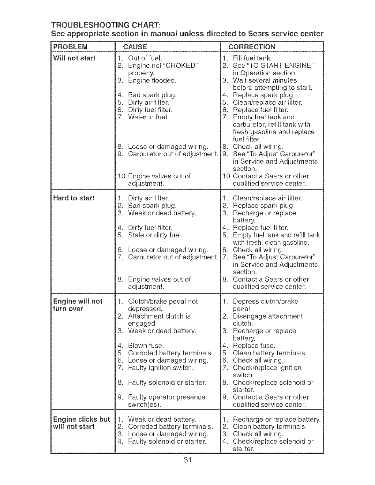
TROUBLESHOOTmNG CHART:
See appropriate section in manuam unmess directed to Sears service center
PROBLEM CAUSE CORRECTmON
Wiii not start
Hard to start
Engine wiii not
turn over
Engine clicks but
wiii not start
1. Out of fuel.
2. Engine not "CHOKED"
properly.
3. Engine flooded.
4. Bad spark plug.
5. Dirty air filter.
6. Dirty fuel filter.
7 Water in fuel.
8. Loose or damaged wiring.
9. Carburetor out of adjustment.
10. Engine valves out of
adjustment.
1. Dirty air filter.
2. Bad spark plug.
3. Weak or dead battery.
4. Dirty fuel filter.
5. Stale or dirty fuel.
6. Loose or damaged wiring.
7. Carburetor out of adjustment.
8. Engine valves out of
adjustment.
1. Clutch/brake pedal not
depressed.
2. Attachment clutch is
engaged.
3. Weak or dead battery.
4. Blown fuse.
5. Corroded battery terminals.
6. Loose or damaged wiring.
7. Faulty ignition switch.
8. Faulty solenoid or starter.
9. Faulty operator presence
switch(es).
1. Weak or dead battery.
2. Corroded battery terminals.
3. Loose or damaged wiring.
4. Faulty solenoid or starter.
1. Fill fueltank.
2. See "TO START ENGINE"
in Operation section.
3. Wait several minutes
before attempting to start.
4. Replace spark plug.
5. Clean/replace air filter.
6. Replace fuel filter.
7. Empty fuel tank and
carburetor, refill tank with
fresh gasoline and replace
fuel filter.
8. Check all wiring.
9. See "To Adjust Carburetor"
in Service and Adjustments
section.
10. Contact a Sears or other
qualified service center.
1. Clean/replace air filter.
2. Replace spark plug.
3. Recharge or replace
battery.
4. Replace fuel filter.
5. Empty fuel tank and refill tank
with fresh, clean gasoline.
6. Check all wiring.
7. See "To Adjust Carburetor"
in Service and Adjustments
section.
8. Contact a Sears or other
qualified service center.
1. Depress clutch/brake
pedal.
2. Disengage attachment
clutch.
3. Recharge or replace
battery.
4. Replace fuse.
5. Clean battery terminals.
6. Check all wiring.
7. Check/replace ignition
switch.
8. Check/replace solenoid or
starter.
9. Contact a Sears or other
qualified service center.
1. Recharge or replace battery.
2. Clean battery terminals.
3. Check all wiring.
4. Check/replace solenoid or
starter.
31
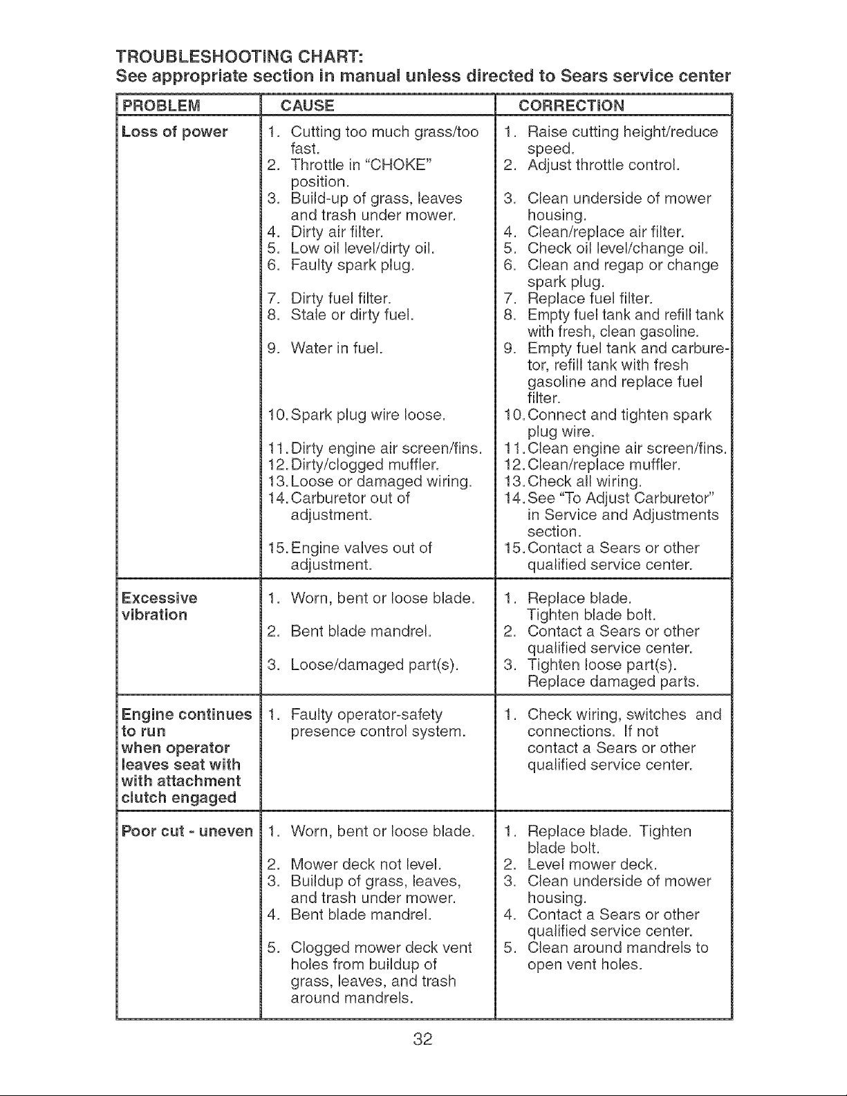
TROUBLESHOOTmNG CHART:
See appropriate section in manuam unmess directed to Sears service center
PROBLEM CAUSE CORRECTmON
Loss of power
.
i2.
3.
i4.
J5.
6.
7.
i8.
9.
Cutting too much grass/too
fast.
Throttle in "CHOKE"
position.
Build=up of grass, leaves
and trash under mower.
Dirty air filter.
Low oil level/dirty oil.
Faulty spark plug.
Dirty fuel filter.
Stale or dirty fuel.
Water in fuel.
1. Raise cutting height/reduce
speed.
2. Adjust throttle control.
3. Clean underside of mower
housing.
4. Clean/replace air filter.
5. Check oil level/change oil.
6. Clean and regap or change
spark plug.
7. Replace fuel filter.
8. Empty fuel tank and refill tank
with fresh, clean gasoline.
9. Empty fuel tank and carbure-
tor, refill tank with fresh
gasoline and replace fuel
filter.
Excessive
vibration
Engine continues
to run
when operator
leaves seat with
with attachment
clutch engaged
Poor cut o uneven
10.Spark plug wire loose.
11. Dirty engine air screen/fins.
12. Dirty/clogged muffler.
13. Loose or damaged wiring.
14. Carburetor out of
adjustment.
15.Engine valves out of
adjustment.
1. Worn, bent or loose blade.
i2. Bent blade mandrel.
3. Loose/damaged part(s).
1. Faulty operator=safety
presence control system.
.
i2.
3.
i4.
i5.
Worn, bent or loose blade.
Mower deck not level.
Buildup of grass, leaves,
and trash under mower.
Bent blade mandrel.
Clogged mower deck vent
holes from buildup of
grass, leaves, and trash
around mandrels.
10. Connect and tighten spark
plug wire.
11. Clean engine air screen/fins.
12. Clean/replace muffler.
13.Check all wiring.
14. See "To Adjust Carburetor"
in Service and Adjustments
section.
15. Contact a Sears or other
qualified service center.
1. Replace blade.
Tighten blade bolt.
2. Contact a Sears or other
qualified service center.
3. Tighten loose part(s).
Replace damaged parts.
.
Check wiring, switches and
connections. If not
contact a Sears or other
qualified service center.
1. Replace blade. Tighten
blade bolt.
2. Level mower deck.
3. Clean underside of mower
housing.
4. Contact a Sears or other
qualified service center.
5. Clean around mandrels to
open vent holes.
32
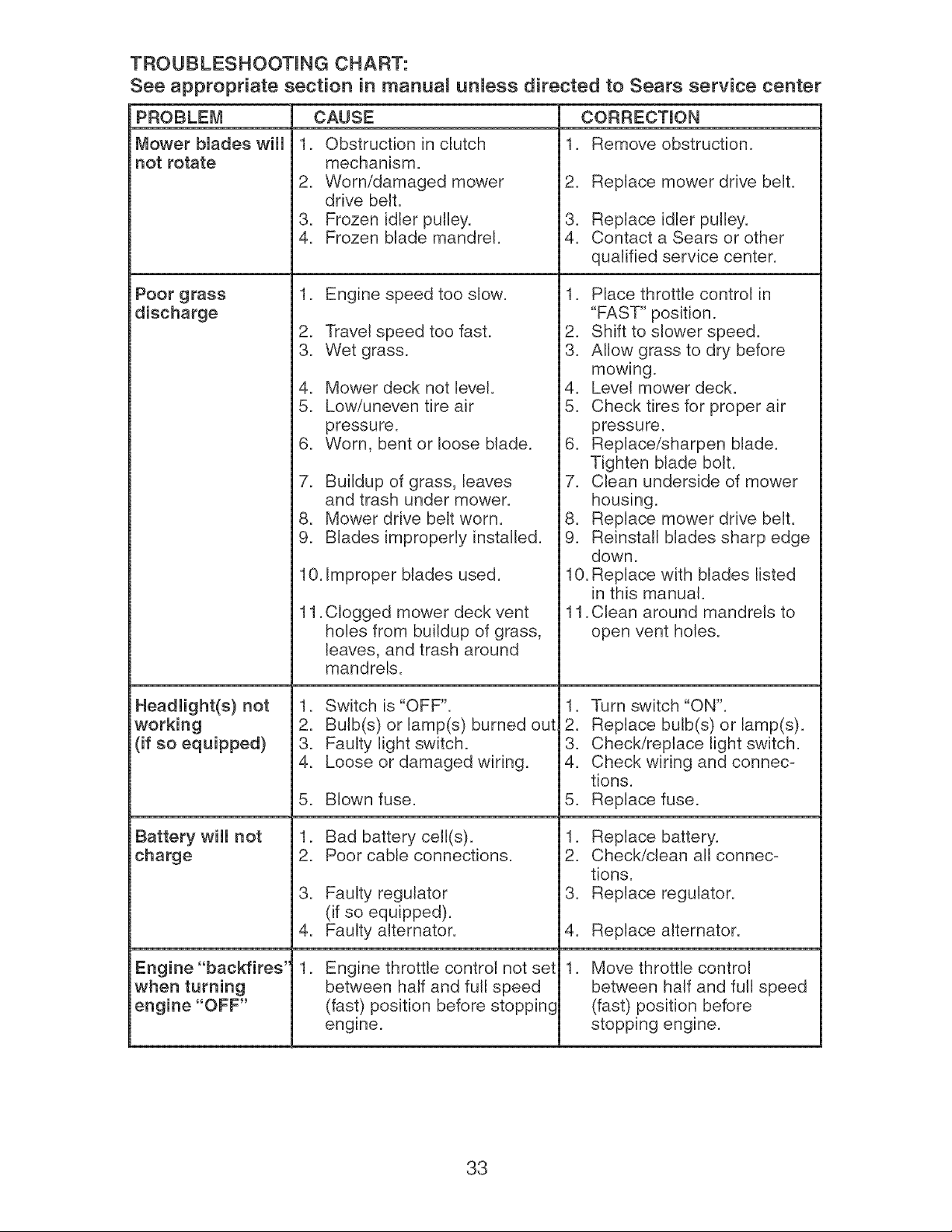
TROUBLESHOOTmNG CHART:
See appropriate section in manuam unmess directed to Sears service center
PROBLEM
Mower blades wiii
not rotate
Poor grass
discharge
Headlight(s) not
working
(if so equipped)
Battery wiii not
charge
Engine "backfires"
when turning
engine "OFF"
CAUSE
1. Obstruction in clutch
mechanism.
2. Worn/damaged mower
drive belt.
3. Frozen idler pulley.
4. Frozen blade mandrel.
1. Engine speed too slow.
2. Travel speed too fast.
3. Wet grass.
4. Mower deck not level.
5. Low/uneven tire air
pressure.
6. Worn, bent or loose blade.
7. Buildup of grass, leaves
and trash under mower.
8. Mower drive belt worn.
9. Blades improperly installed.
10. Improper blades used.
11. Clogged mower deck vent
holes from buildup of grass,
leaves, and trash around
mandrels.
1. Switch is "OFF".
2. Bulb(s) or lamp(s) burned out
3. Faulty light switch.
4. Loose or damaged wiring.
5. Blown fuse.
1. Bad battery cell(s).
2. Poor cable connections.
3. Faulty regulator
(if so equipped).
4. Faulty alternator.
.
Engine throttle control not set
between half and full speed
(fast) position before stopping
engine.
CORRECTmON
1. Remove obstruction.
2. Replace mower drive belt.
3. Replace idler pulley.
4. Contact a Sears or other
qualified service center.
1. Place throttle control in
"FAST" position.
2. Shift to slower speed.
3. Allow grass to dry before
mowing.
4. Level mower deck.
5. Check tires for proper air
pressure.
6. Replace/sharpen blade.
Tighten blade bolt.
7. Clean underside of mower
housing.
8. Replace mower drive belt.
9. Reinstall blades sharp edge
down.
10. Replace with blades listed
in this manual.
11. Clean around mandrels to
open vent holes.
1. Turn switch "ON".
2. Replace bulb(s) or lamp(s).
3. Check/replace light switch.
4. Check wiring and connec-
tions.
5. Replace fuse.
1. Replace battery.
2. Check/clean all connec=
tions.
3. Replace regulator.
4. Replace alternator.
. Move throttle control
between half and full speed
(fast) position before
stopping engine.
33

34
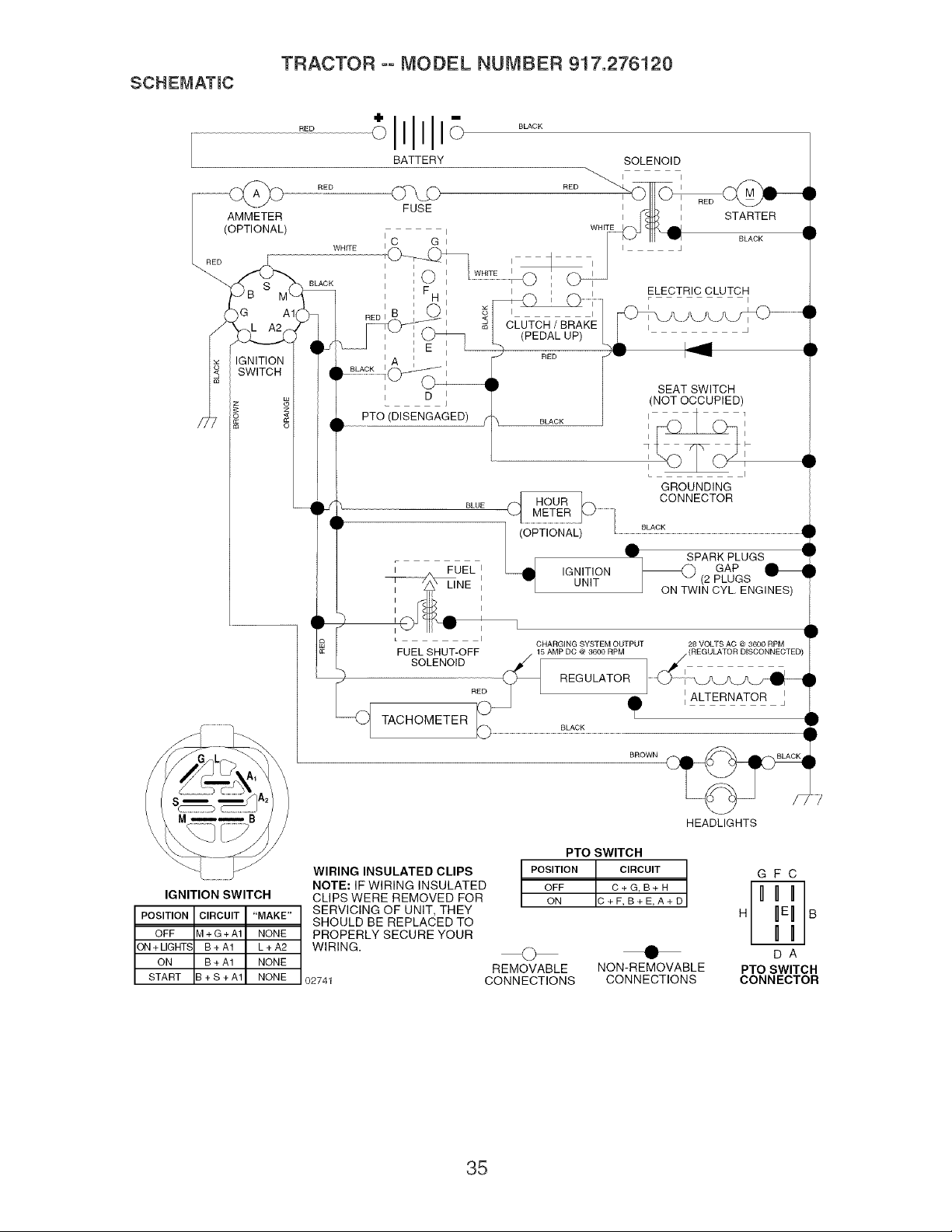
SCHEMATmC
TRACTOR ooMODEL NUMBER 917.276120
_I_[ TACHOMETER
ELECTRIC CLUTCH
SEAT SWITCH
(NOT OCCUPIED)
PTO (DISENGAGED)
GROUNDING
CHARGING SYSTEM OUTPUT 28 VOLTS AC @ 3600 RPM
FUEL SHUT-OFF / (REGULATORDISCONNECTEE
I ALTERNATOR
BROWN
HEADLIGHTS
I
PTO SWITCH
POSITION CIRCUIT
OFF C+G,B+H
ON S+F,B+E,A+D
WIRING INSULATED CLIPS
NOTE: IF WIRING INSULATED
CLIPS WERE REMOVED FOR
SERVICING OF UNIT, THEY
SHOULD BE REPLACED TO
PROPERLY SECURE YOUR
WIRING.
GFC
IGNITION SWITCH
POSITION CIRCUIT "MAKE" H B
OFF _I+G+A1 NONE
ON + LIGHT_ B+A1 L+A2 @ • D A
ON B + A1 NONE
REMOVABLE NON-REMOVABLE PTO SWITCH
START 3 + S + A1 NONE 02741 CONNECTIONS CONNECTIONS CONNECTOR
35
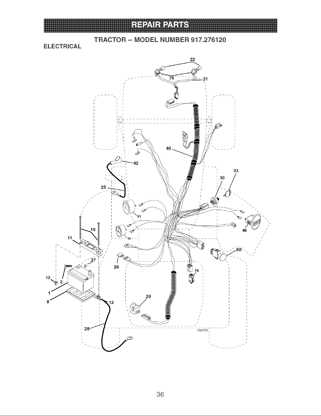
TRACTOR oo MODEL NUMBER 917.276120
ELECTRmCAL
I \
F
22
I
i
T
i
\ i
\ !
\,,
_ _27 ,
,28f [ .........._,..........................................................................................._58_57.....
36

ELECTRmCAL
TRACTOR oo MODEL NUMBER 917.276120
KEY PART
NO. NO. DESCRmPTmON
1 144927 Battery
2 74760412 Bolt Hex Head 1/4-20 x 3/4
8 7603J Tray, Battery
10 145211 Bolt 1/4-20 x 7.5 Zinc
11 150109 Hold down Battery Dash Mount
12 145769 Nut Push Nylon 1/4"
16 176138 Switch Interlock
21 175688 Harness Asm. Light
22 4152J Bulb Light
25 185456 Cable 4 Ga. 31" Red CV25 w/16.W.
26 108824X Fuse
27 73510400 Nut, Keps Hex 1/4-20 uric
28 170697 Cable, Ground
29 121305X Switch, Hunger
30 175566 Switch, Ign
33 140403 Key, Ignition
40 188033 Harness Ign.
42 154336 Cover TerminaI
45 177500 Ammeter
46 177501 Meter, Hour
50 174652 Switch, PTO
79 175242 Socket Asm. Bulb
91 184932 Tachometer Round
NOTE: All component dimensions given in U. S.
inches 1 inch = 25.4 mm
37
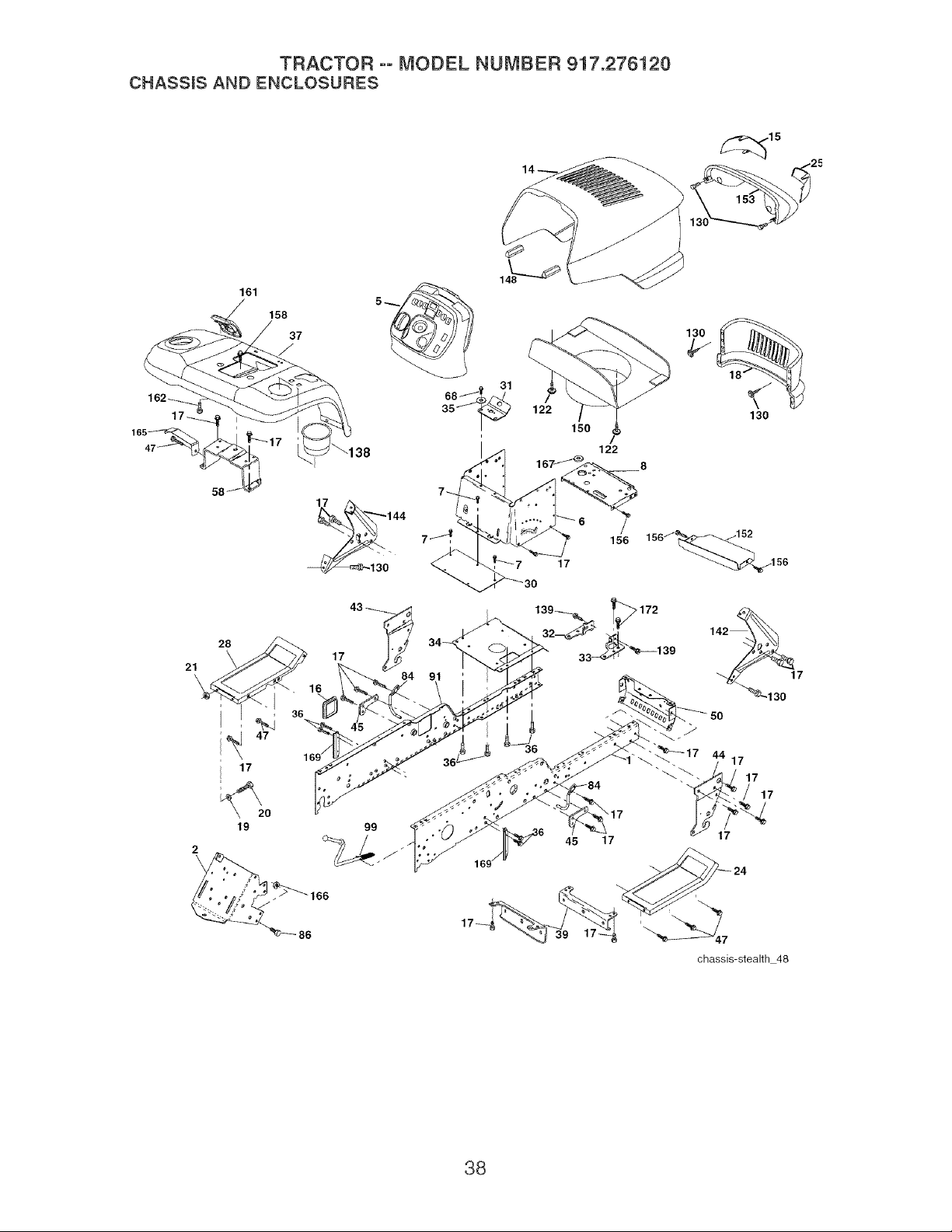
TRACTOR ooMODEL NUMBER 917.276120
CHASSmSAND ENCLOSURES
21
2
\
58
161
28
17
19
158
37
16
36
47
169/'
86
99
122
150
153
130
130
122
8
17
45
chassis-stealth 48
38

TRACTOR oo MODEL NUMBER 917.276120
CHASSmS AND ENCLOSURES
KEY PART KEY PART
NO, NO, DESCRiPTiON NO, NO, DESCRiPTiON
1 180375 Rail, Frame RH 47 17490608
2 175282 Drawbar, Gt 50 175476
5 187934X428 Dash YTGT 2 Cyl 58 183569
6 157882 Dash, Lower Vgt One Piece 68 17490508
7 17720408 Screw, Thd Cut 1/4-20 x 1/2 84 188164
8 184668 Support, Battery 86 74780616
14 175260X615 Hood Asm 91 180374
15 161841 Lens LH 99 177143
16 121794X Cover, Access 122 161464
17 17000612 Screw 3/8-16 x =75 130 191611
18 174515X615 Grille 138
19 19131312 Washer 13/32x13/16x12Ga= 139 171873
20 STD523710 Bolt, Fin Hex 3/8-16 x 1 142 161897
21 STD541437 Nut Crownlock 3/8-16 unc 144 161900
24 179717X615 Footrest, RH 148 164655
25 161842 Lens RH 150 175352
28 179716X615 Footrest, LH 152 177956
30 145052 Saddle, Hydro 153 179763
31 161419 Brace, Supt 1-pcVGT 156 17000512
32 161327 Bracket, Pivot Chassis Lh 158 17670608
33 161326 Bracket, Pivot Chassis Rh 161
34 177018 Plate Asm Engine 162
35 19111116 Washer 11/32 x 11/16 x 16 Ga= 165
36 17060512 Screw 5/16-18 x 3/4 166
37 178510X615 Fender Pnt 167
39 175278 Bracket, Axle Front 169
43 136939 Bracket, Spnsn Front Lh 172
44 136940 Bracket, Spnsn Front Rh
45 187270 Bracket Asm. Susp Chas=
Screw ThdroI. 3/8-16 x 1/2
Bracket, Chassis Front
Bracket Asm. Fender
Screw Thdrol. 5/16-18 x 1/2
Upstop 54" Deck
Bolt Fin Hex 7/16-14 uric x 1
Rail, Frame Lh
Rod By Pass
Screw Hex Wshd 8-18 x 7/8
Screw 10 x 3/4 Single Lead-Hex
191121X428 Cup Holder
Bolt Shoulder 5/16-18 TT
Bracket Dash Rh
Bracket Dash Lh
Extrusion Bumpers
Duct Heat Hood
Shield Browning
Light Asm= DuaI
Screw 5/16-18 x 3/4
Screw ThdroI 3/8-16 x 1/2
179612X428 Console Fuel Window
142432 Screw Hex 1/4-1/2 uric
183554 Bracket Support Tank
73680700 Nut
184672 Bushing, Snap NyIon 1=250
188598 Bracket Chassis Sway
17120614 Screw 3/8-16 x =875
NOTE: All component dimensions given in U=S=
inches 1 inch = 25=4 mm
39

TRACTOR °° MODEL NUMBER 917.276120
GROUND DRmVE
117_
128 50\
127 120
153_
77
65
122
117_
9
69
33
drive 6-vgt
143
36
4O

TRACTOR oo MODEL NUMBER 917.276120
GROUND DRmVE
KEY PART KEY PART
NO, NO, DESCRiPTiON NO. NO. DESCRIPTmON
1 Transaxle Hydro Gear 98 141004
311-3500 (See Breakdown) 106 142918
2 7070E Key 1/4 x 2=5 107 154739
3 7563R Washer Thrust 108 142917
6 STD561210 Pin, Cotter 111 156240
7 140507 HubWheel Asm= 112 178588
9 140080 Bolt Hub 114 73800500
20 73940800 Nut 117 73900600
22 180235 Lever Asm Shift Lower 120 17000612
23 130564 Knob 121 175611
29 176600 Brake, Rod 122 72010520
33 12000053 Ring E
34 71673 Cap, Parking Brake 123 183254
35 137648 Rod, Parking Brake 124 165492
36 149412 Spring, Drive Ground 125 17000512
37 121749X Washer 25/32 x 1-1/4 x 16 Ga= 126 166002
38 150035 Nyliner
39 74321016 Screw, Fin= #10-24 x 1 127 177362
40 178575 Actuator, Interlock Switch 128 176624
41 73931000 Nut Center!ock 10-24 unc 129 179473
42 8883R Cover, Pedat 130 19131016
46 145170 Retainer, Spring 131 76020312
48 72110614 Bolt, RDHD 3/8-16 x 1-3/4 Gr=5 132 175467
50 131494 Pulley, Idler, Flat 133 175468
52 127783 Pulley, Idler, Grooved 135 177364
55 105706X Bearing, Idler 137 1685H
56 161597 V-Belt 138 1370H
58 74760724 Bolt Fin Hex 7/16-14 x 1-1/2 142 175469
61 143995 Pulley, Transaxle 143 17060512
64 176601 Shaft, Clutch/Brake PedaI 145 163168
65 179613 Bolt, Shoulder 146 140462
68 STD571812 Pin, RolI 147 141322
69 123800X Washer 1-1/32 x 1-5/8 x 16 Ga= 151 74760514
70 179121X428 Console Automatic YT/GT 152 178705
73 74490548 Bolt Hex Flghd 5/16-18 x 3 Gr. 5 153 4497H
74 142432 Screw Hex Wsh= Hi-Lo 1/4-1/2
77 74780716 Bolt Fin Hex 7/16-14 x 1
89 73680700 Nut Crownlock 7/16-14 unc
94 133835 Fastener Christmas Tree
Bracket Shift
O-Ring Asm Hydro Gear
Line Fuel Hydro 15"VGT
Cap Asm Vent Hydro Gear 70109
Spacer Shift Lever VGTH
Washer Nylon High Temp
Nut Lock Hx W/Ins 5/16-18 uric
Nut, Lock Hg= 3/8-16
Screw 3/8-16 x .75
Bracket Strap Torque
Bolt RDHD SQ
5/16-18 unc x 2-1/2
Rod Shift
Bolt ShouIder 5/16-18 x =561
Screw 5/16-18 x 5/8
Washer SRRTD
5/161D x 1=0x =125
Link Control Clutch
Spring Drive GRND
Bracket Asm Idler Tensioning
Washer 13/32 x 5/8 x 16 Ga=
Pin Cotter 3/32 x 3/4
Bracket Mtg Hydro 3500 LH VGT
Bracket Mtg Hydro 3500 RH VGT
Link Asm Control Hydro 3500
Nut Lock 5/16-18 NC Thd
Washer Thrust 5/8 x 1=10 x 1/32
Strap Torque HG-3500
Screw ThdroI 5/16-18 x 3/4
Washer AxIe Flange
Fan 7" Hydro
Washer
Bolt Fin Hex 5/16-18 uric x 7/8
Bolt Hex 5/16-18 x 1
Retainer Spring
NOTE: All component dimensions given in U=S=
inches 1 inch = 25=4 mm
41
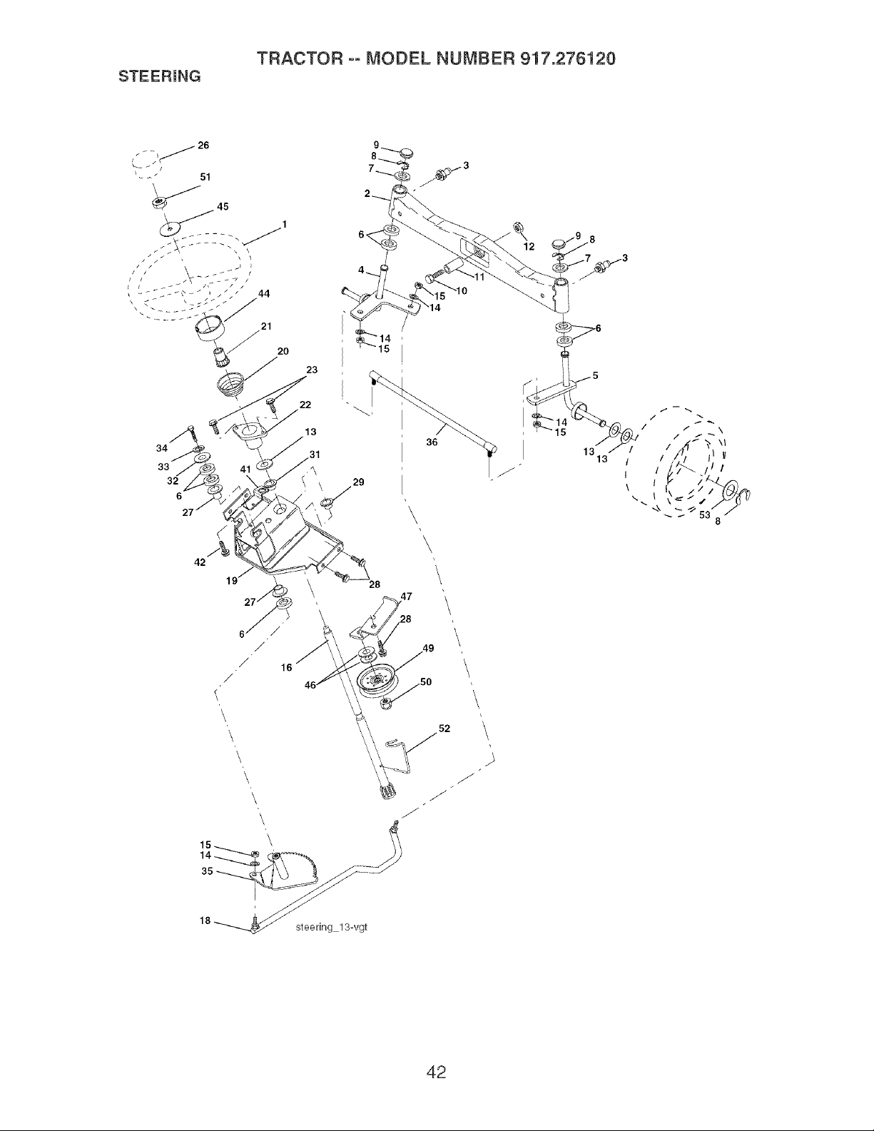
STEERmNG
TRACTOR °° MODEL NUMBER 917.276120
34
33
32
6
42
23
22
13
,31
29
28
36
\
J
18 _ steering 13-vgt
52
42

STEERmNG
TRACTOR °° MODEL NUMBER 917.276120
KEY PART
NO. NO.
1 159944X428
2 178557
3 183226
4 161849
5 161848
6 6266H
7 121748X
8 12000029
9 184946X505
10 74781044
11 136518
12 73901000
13 121749X
14 STD551137
15 73540600
16 186814
18 187799
19 156011
20 163887X428
21 159945
22 155105
23 152927
26 159946X428
27 3366R
28 17000612
29 104239X
31 138136
32 19111610
33 STD551131
34 74780512
35 187039
36 186799
41 155246
42 17490508
44 160135X428
45 19182411
46 19131610
47 179471
49 175820
50 73900600
51 73940800
52 175553
53 188967
DESCRIPTION
Wheel, Steering
Axle Asm, Front
Fitting, Grease
Spindle Asm, LH
Spindle Asm., RH
Bearing, Race Thrust Harden
Washer 25/32 x 1-5/8 x 16 Ga.
Ring, Klip #T5304-75
Cap, Spindle
Bolt, Fin Hex 5/8-11 x 2-3/4
Spacer Bearing Axte Front
Nut, Lock Flange 5/8-11 uric
Washer 25/32 x 1-1/4 x 16 Ga.
Washer, Lock Hvy Hid Spr 3/8
Nut, Crownlock 3/8-24
Shaft Asm, Steering
Dragl+nk
Support Asm, Steering Vgt
Boot, Steering
Adapter, Wheel Steering
Bushing, Strg. BIk
Screw
Insert, Wheel Steering
Bearing, Col. Strg.
Screw, 3/8-16 x 3/4
Bearing, Flange
Bushing, Nyliner Snap
Washer 11/32 x 1 x 10 Ga.
Washer, Lock Hvy Hlcl Spr 5/16
Bolt Fin Hex 5/16-18 uric x 3/4
Gear, Sector Steering
Tie Rod
Bracket Switch Interlock VGT 97
Screw Thdro! 5/16-18 x 1/2 Tyt
Extension Steering
Washer 9/16 x 1-1/20 x 11 Ga.
Washer 13/32 x 1 x 10 Ga.
Bracket Asm Idler Stationary
Pulley Idler Flat
Nut Lock Fig 3/8-16 unc
Nut Hrx Jam Toplock 1/2-20 unf
Clip Steering
Washer Harden +793 x 1+637 x +060
NOTE: All component dimensions given in U. S.
inches 1 inch = 25.4 mm
43
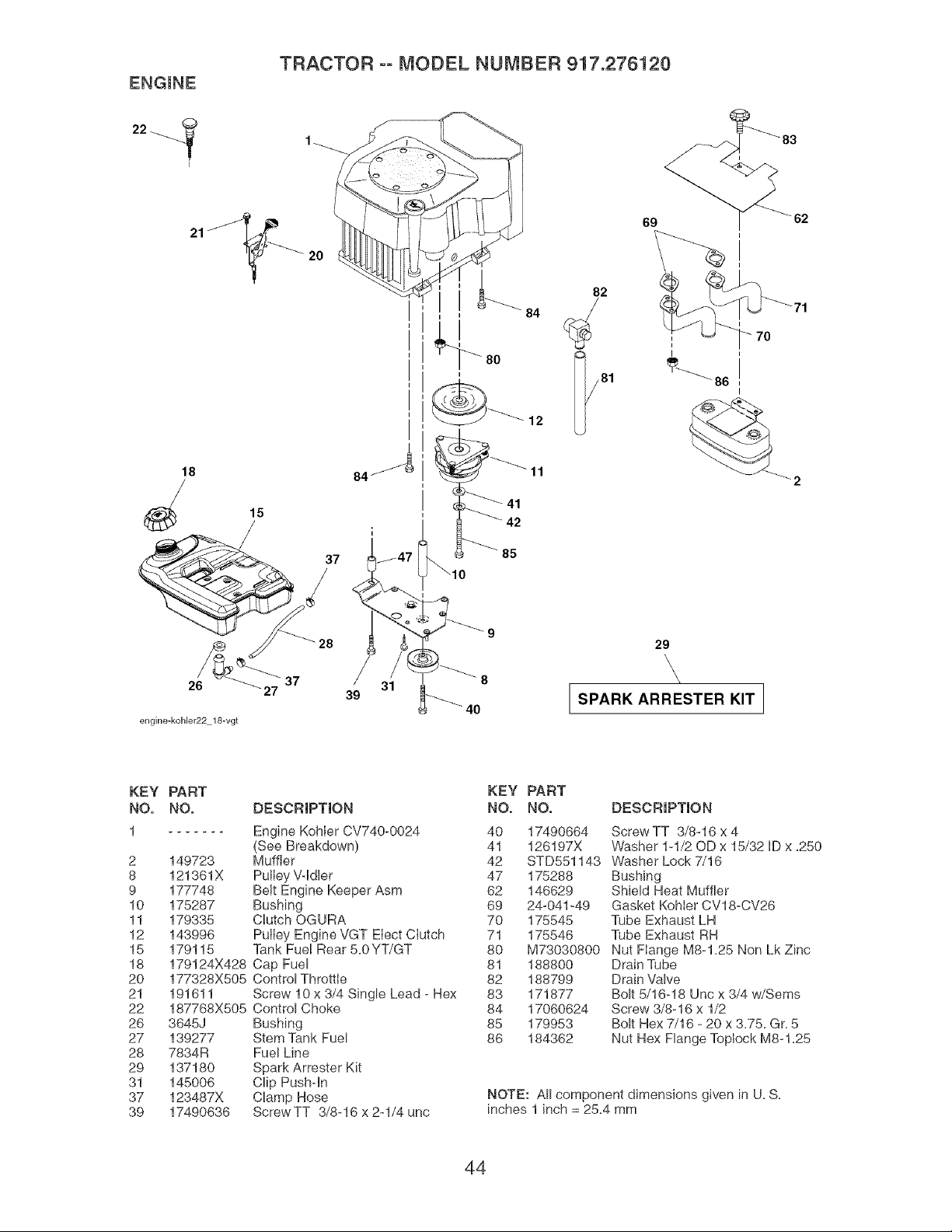
ENGINE
TRACTOR ooMODEL NUMBER 917.276120
22_
I
2O
18
28
26 27
engine-koMer22 18-vgt
39
31
12
11
_- 41
42
85
8
4O
82
69
29
SPARK ARRESTER KIT
KEY PART
NO. NO.
1
2
8
9
10
11
12
15
18
20
21
22
26
27
28
29
31
37
39
149723
121361X
177748
175287
179335
143996
179115
179124X428
177328X505
191611
187768X505
3645J
139277
7834R
137180
145006
123487X
17490636
DESCRIPTION
Engine KohIer CV740-0024
(See Breakdown)
Muffler
Pulley Vddler
Belt Engine Keeper Asm
Bushing
Clutch OGURA
PuIIey Engine VGT EIect CIutch
Tank Fue! Rear 5=0YT/GT
Cap Fuel
Control Throttle
Screw 10 x 3/4 Single Lead - Hex
Control Choke
Bushing
Stem Tank Fuel
Fuel Line
Spark Arrester Kit
Clip Pushdn
Clamp Hose
ScrewTT 3/8-16 x 2-1/4 unc
KEY PART
NO. NO. DESCRIPTION
40 17490664 Screw TT 3/8-16 x 4
41 126197X Washer 1-1/20D x 15/32 ID x =250
42 STD551143 Washer Lock 7/16
47 175288 Bushing
62 146629 Shield Heat Muffler
69 24-041-49 Gasket KohIer CV18-CV26
70 175545 Tube Exhaust LH
71 175546 Tube Exhaust RH
80 M73030800 Nut Flange M8-1=25 Non LRZinc
81 188800 Drain Tube
82 188799 Drain Valve
83 171877 Bolt 5/16-18 Unc x 3/4 w/Sems
84 17060624 Screw 3/8-16 x 1/2
85 179953 Bolt Hex 7/16 - 20 x 3=75=G r=5
86 184362 Nut Hex Flange TopJock M8-1 =25
NOTE: All component dimensions given in U=S=
inches 1 inch = 25=4 mm
44
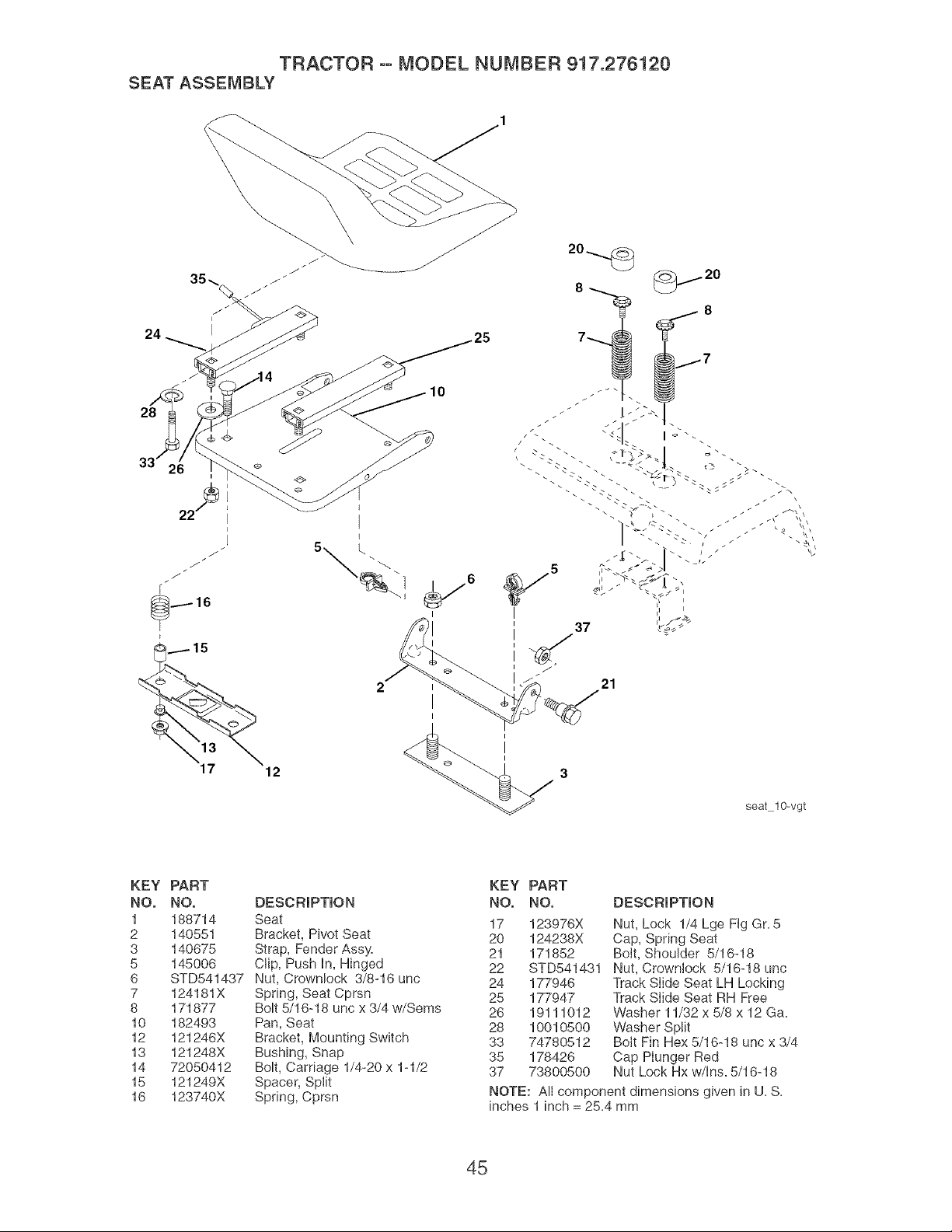
TRACTOR ooMODEL NUMBER 917.276120
SEAT ASSEMBLY
24
28
10
17
12
seat 10-vgt
KEY PART
NO. NO.
1 188714
2 140551
3 140675
5 145006
6 STD541437
7 124181X
8 171877
10 182493
12 121246X
13 121248X
14 72050412
15 121249X
16 123740X
DESCRIPTION
Seat
Bracket, Pivot Seat
Strap, Fender Assy.
Clip, Push In, Hinged
Nut, Crownlock 3/8-16 unc
Spring, Seat Cprsn
Bolt 5/16-18 unc x 3/4 w/Sems
Pan, Seat
Bracket, Mounting Switch
Bushing, Snap
Bolt, Carriage 1/4-20 x 1-1/2
Spacer, Split
Spring, Cprsn
KEY PART
NO. NO. DESCRIPTION
17 123976X
20 124238X
21 171852
22 STD541431
24 177946
25 177947
26 19111012
28 10010500
33 74780512
35 178426
37 73800500
Nut, Lock 1/4 Lge Fig Gr. 5
Cap, Spring Seat
Bolt, Shoulder 5/16-18
Nut, Crownlock 5/16-18 unc
Track Slide Seat LH Locking
Track SIide Seat RH Free
Washer 11/32 x 5/8 x 12 Ga.
Washer Split
Bolt Fin Hex 5/16-18 unc x 3/4
Cap Hunger Red
Nut Lock Hx w/Ins. 5/16-18
NOTE: Allcomponentdimensions givenin U.S.
inches 1 inch = 25.4mm
45
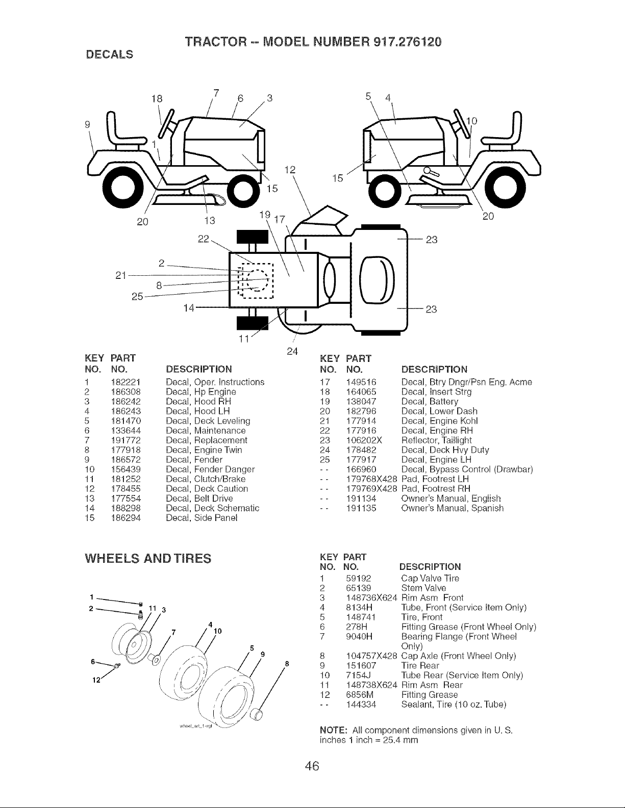
DECALS
TRACTOR oo MODEL NUMBER 917.276120
18
5 4
12
15
21
25
KEY PART
NO. NO.
1 182221
2 186308
3 186242
4 186243
5 181470
6 133644
7 191772
8 177918
9 186572
10 156439
11 181252
12 178455
13 177554
14 188298
15 186294
2O
13
19
8
14--
11
DESCRIPTION
Deca! Oper= Instructions
DecaI Hp Engine
Decal Hood RH
Decal Hood LH
Deca! Deck Leveling
Decal Maintenance
Decal Replacement
Decal Engine Twin
Decal Fender
Decal Fender Danger
Decal Clutch/Brake
Decal Deck Caution
DecaI Belt Drive
Deca! Deck Schematic
Decal Side Panel
24
20
23
23
KEY PART
NO. NO. DESCRIPTION
17 149516 Decal, Btry Dngr/Psn Eng=Acme
18 164065 Decal, Insert Strg
19 138047 Decal, Battery
20 182796 Decal, Lower Dash
21 177914 Decal, Engine KoH
22 177916 Decal, Engine RH
23 106202X Reflector, Taillight
24 178482 Decal, Deck Hvy Duty
25 177917 Decal, Engine LH
_ 166960 Decal, Bypass Control (Drawbar)
_ 179768X428 Pad, Footrest LH
_ 179769X428 Pad, Footrest RH
_ 191134 Owner's Manual, English
_ 191135 Owner's Manual, Spanish
WHEELS ANDTmRES
4
10
5
9
8
KEY PART
NO. NO. DESCRIPTION
1 59192 Cap Valve Tire
2 65139 Stem Valve
3 148736X624 Rim Asm Front
4 8134H Tube, Front (Service Item Only)
5 148741 Tire, Front
6 278H Fitting Grease (Front Wheel Only)
7 9040H Bearing Flange (Front Wheel
Only)
8 104757X428 Cap Axle (Front Wheel Only)
9 151607 Tire Rear
10 7154J Tube Rear (Service Item Oniy)
11 148738X624 Rim Asm Rear
12 6856M Fitting Grease
- - 144334 Sealant, Tire (10 oz. Tube)
NOTE: All component dimensions given in U. S.
inches 1 inch = 25.4 mm
46
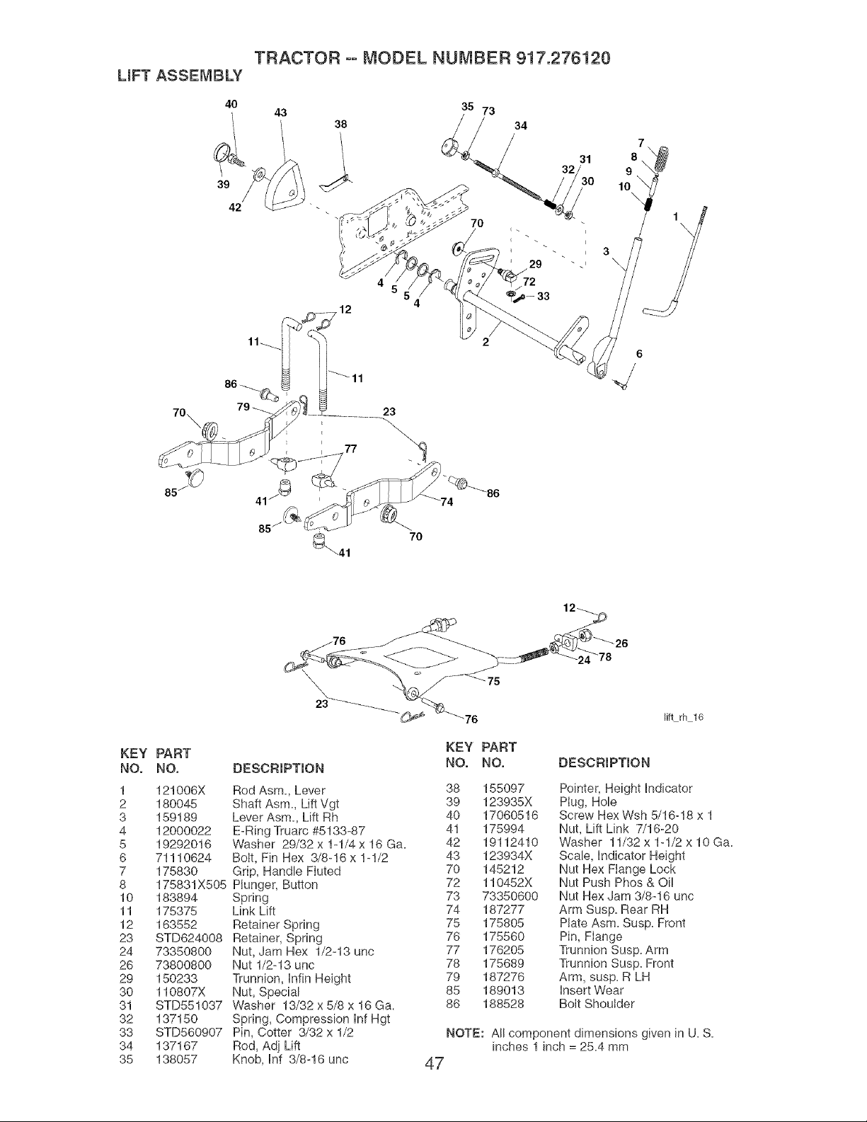
LmFT ASSEMBLY
40
TRACTOR °° MODEL NUMBER 917.276120
43
38
35 73
34
32
70
72
31
3
\
7
9
10
\
85
_41
70
12_
_76 _ _,_26
23 _. -- _
KEY PART
NO. NO. DESCRiPTiON
1 121006X Rod Asm., Lever
2 180045 Shaft Asm, Lift Vgt
3 159189 Lever Asm, Lift Rh
4 12000022 E-Ring Truarc #5133-87
5 19292016 Washer 29/32 x 1-1/4 x 16 Ga.
6 71110624 Bolt, Fin Hex 3/8-16 x 1-1/2
7 175830 Grip, Handle FIuted
8 175831X505 Plunger, Button
10 183894 Spring
11 175375 Link Lift
12 163552 Retainer Spring
23 STD624008 Retainer, Spring
24 73350800 Nut, Jam Hex 1/2-13 unc
26 73800800 Nut 1/2-13 unc
29 150233 Trunnion, hfin Height
30 110807X Nut, Special
31 STD551037 Washer 13/32 x 5/8 x 16 Ga.
32 137150 Spring, Compression Inf Hgt
33 STD560907 Pin, Cotter 3/32 x 1/2
34 137167 Rod, Adj Lift
35 138057 Knob, Inf 3/8-16 unc
_iftrh 16
KEY PART
NO. NO. DESCRIPTION
38 155097 Pointer, Height Indicator
39 123935X Plug, Hole
40 17060516 Screw Hex Wsh 5/16-18 x 1
41 175994 Nut, Lift Link 7/16-20
42 19112410 Washer 11/32 x 1-1/2 x 10 Ga.
43 123934X Scale, Indicator Height
70 145212 Nut Hex Flange Lock
72 110452X Nut Push Phos & Oi!
73 73350600 Nut Hex Jam 3/8-16 unc
74 187277 Arm Susp. Rear RH
75 175805 Plate Asm. Susp. Front
76 175560 Pin, Flange
77 176205 Trunnion Susp. Arm
78 175689 Trunnion Susp. Front
79 187276 Arm, susp. R LH
85 189013 Insert Wear
86 188528 Bolt Shoulder
NOTE: All component dimensions given in U. S.
inches 1 inch = 25.4 mm
47
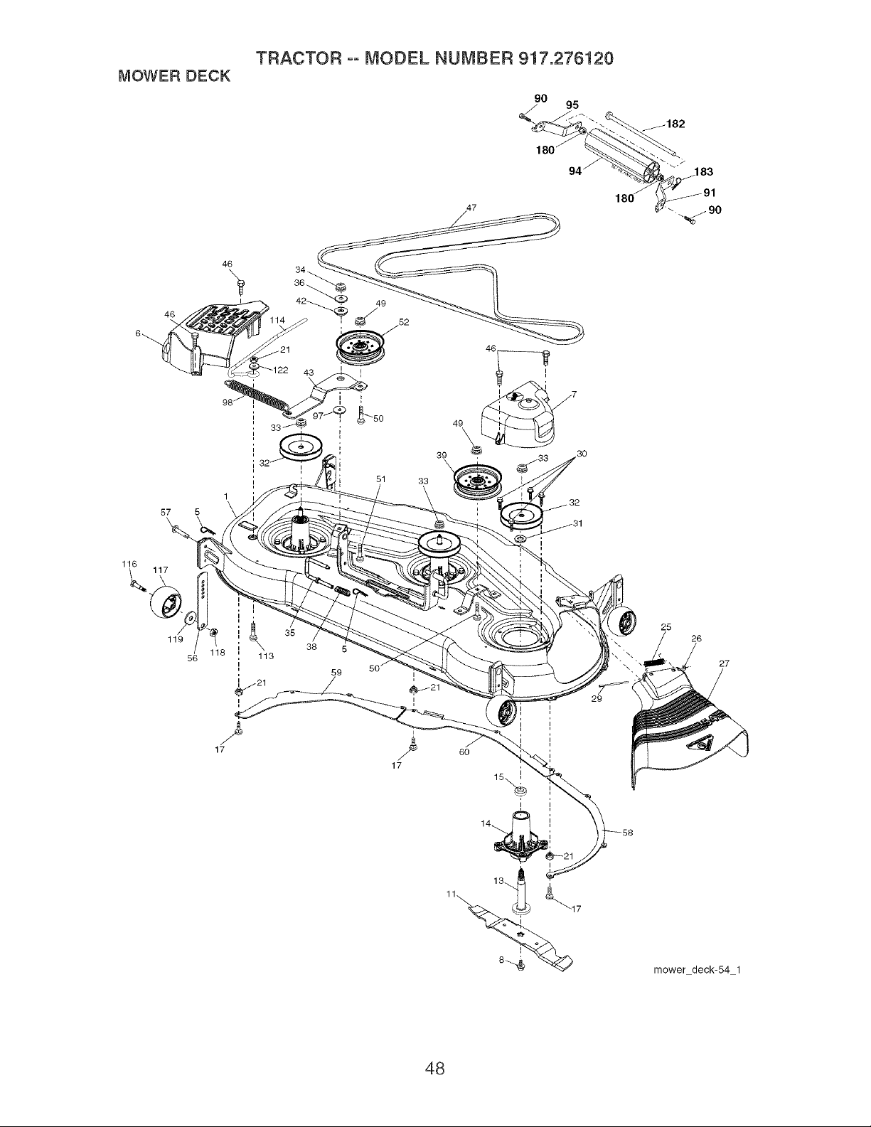
MOWERDECK
46
57 5
\
116
117
119
56
47
46 34__
39
\
51 33
17
35
38 5
59
17
29
25
26
27
mower deck-54-1
48

TRACTOR oo MODEL NUMBER 917.276120
MOWER DECK
KEY PART
NO. NO. DESCRiPTiON
1 187295 Deck Weldment Mower
5 4939M Retainer Spring
6 187297 Cover Mandrel LH
7 188187 Cover Mandre! RH
8 174365 Bolt 7/16 Asm= Blade
11 187254 Blade, Standard
(For mulching mowers only)
13 187292 Shaft Asm= w/Lower Bearing
14 187281 Housing, Mandrel
15 110485X Bearing, Ball, Mandrel
17 72140505 Bolt, Carriage 5/16-18 x 5/8
21 73680500 Nut, Crownlock 5/16-18 uric
25 178102 Spring, Torsion
26 110452X Nut, Push
27 187257X428 Deflector Shield
29 131491 Rod, Hinge
30 173984 Screw, Thdroll Washer Head
31 187690 Washer, Spacer Mower Vented
32 173436 PuIley, Mandrel
33 178342 Nut, Fig=Top Lock Cntr=9/16
34 73680600 Nut
35 188635 Pin Suspension Rear
36 19131316 Washer 13/32 x 13/16 x 16 Ga=
38 188657 Spring Compression
39 187284 PuIley, Idler, Stationary
42 165723 Spacer, Retainer
43 187278 Arm, IdIer
46 137729 Screw, ThdrolL 1/4-20 x 5/8
47 191273 V-Belt, Mower
49 73900600 Nut, Lock Fig. 3/8-16 uric
50 72110616 Bolt, Carr. 3/8-16 x 2
51 72110610 Bolt
52 188460 Pulley Idler Clutching
56 155986 Bar Pnt Adj=
57 156941 Pin Head Rivet
58 187342 Baffle Right
59 187344 Baffle Left
60 187607 Baffle Center
90 74760516 Bolt 5/16-18 x 1
91 180535 Bracket Asm N Roller RH
94 176066 Roller Nose 48"
95 180534 Bracket Asm N Roller LH
97 19133210 Washer 13/32
98 187282 Spring Clutch Drive
113 72110508 Bolt Rdhd Sqnk 5/16-18 x 3/4
114 187556 RodTension Relief
116 184219 Bolt, Shoulder
117 174873 Gauge Wheel
118 73930600 Nut, Centerlock 3/8-16 unc
119 19121414 Washer 3/8 x 7/8 x 14 Ga=
122 187557 Bushing Tension Relief
180 73800500 Nut 5/16-18
182 179127 Rod Roller Nose Narrow
183 163552 Retainer Spring
- - 187292 Mandrel Asm. Service (Includes Key Nos=
13-15 and 33)
- - 188271 Replacement Mower, Complete (Std= Deck-
Order separately nose roller components
key nos= 90, 91,94, 95, 180, 182, 183)
NOTE: All component dimensions given in U. S.
inches 1 inch = 25.4 mm
49
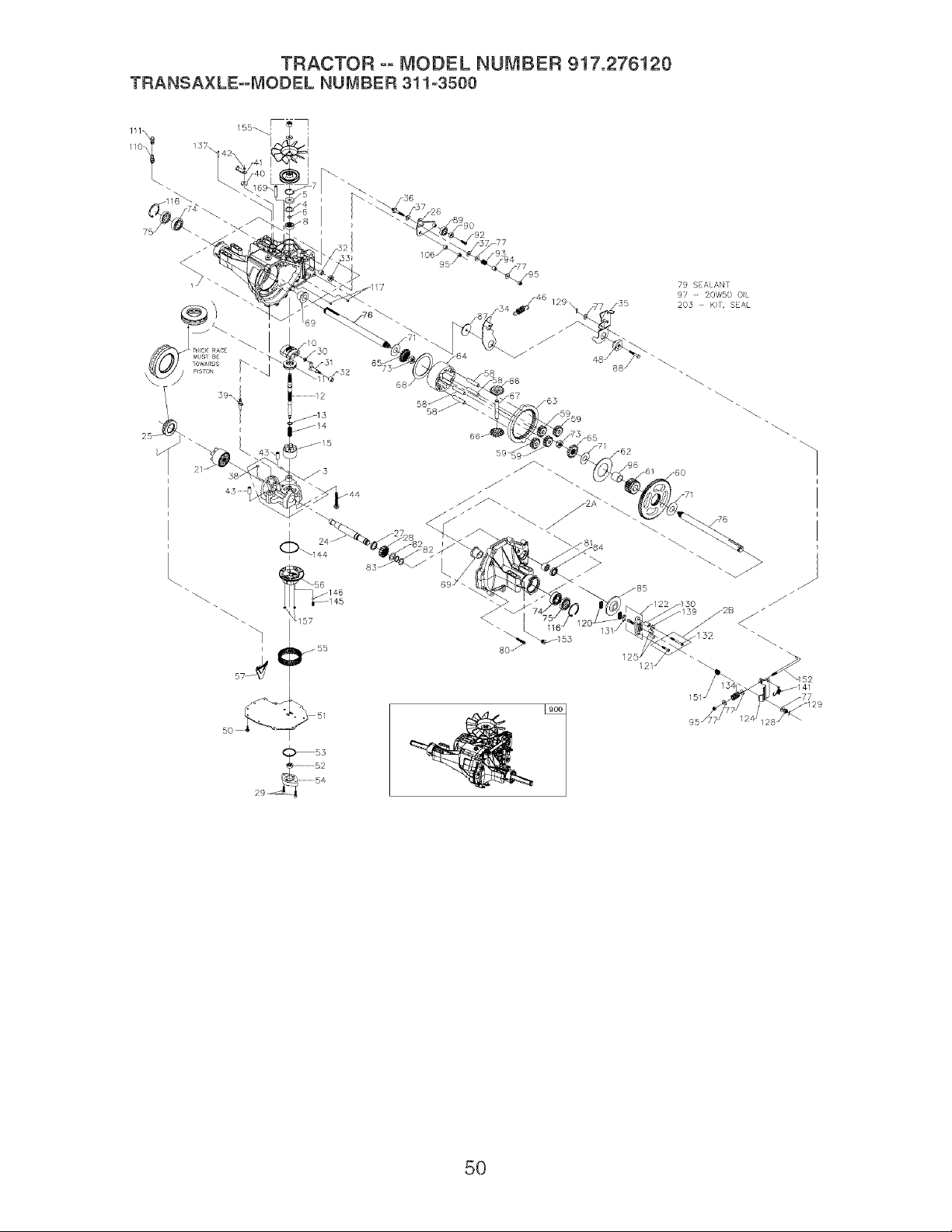
TRACTOR °° MODEL NUMBER 917.276120
TRANSA×LE=-MODEL NUMBER 311-3500
111\
/5
I
.....56 146
!
_55
50_ _ 51
79 SEALANT
97 _ 20W50 O}L
203 - K}r, SEAL
/141
5O

TRACTOR °° MODEL NUMBER 917.276120
TRANSA×LE--MODEL NUMBER 311-3500
Key Part Key Part
No, No, Description No. No,
1 161122 Kit housing main 64 161149
Main housing, Lip seal, Flange bearing 65 193017
Trunnion bushing, Cradle bearing 66 193018
2A 193015 Kit, housing dh 67 161152
R.H. Housing, Flange bearing 68 161153
Needle bearing (sce1412) 69 169534
Lip seal (.875 Id x 1.30D x .25) 71 161155
2B 193016 kit, Brake bolt 73 161156
Bolt, hex hd 1/4-20 x 1.25 W/patch 74 169535
Bolt, hex hd 1/4-20 x 2.25 W/patch 75 161157
3 184703 Kit, center section 76 161158
Center section, Bushing .50 X .60 X .50 77 142884
Bushing .90 X 1.02 X .75 79 178322
Plate bypass, Check plug assembly.044 80 161159
Check plug assembly, no bleed 81 161160
4 161125 Spacer (bdp, bdu 10) 82 161161
5 142932 Seal, lip 83 161162
6 142928 Retaining ring 84 161163
7 142933 Retaining ring 85 161164
8 142934 Bearing, ball 87 178323
10 169524 Swash plate (BDP, BDU 10) 88 178784
11 173159 Bearing, thrust (10cc)
12 161126 Shaft, input (310-3000) 89 178783
13 142978 Washer, block thrust 90 178326
14 142977 Spring, helical compression 92 178787
15 169898 Kit, cylinder block (10cc) 93 142969
10cc cylinder block, 10cc piston 94 142980
10cc piston spring, Piston seat washer 95 169537
21 150786 Block, (BD-21& IHT) 96 169538
21cc cylinder block, Piston seat washer 97
21ccpiston, 21cc piston spring 106 161166
24 161127 Shaft, motor (310-3000) 108 150800
25 169526 Bearing, thrust (21cc) 110 150813
26 161128 Control arm (310-3000)
27 161129 Spacer (310-3000) 111 150812
28 161130 Gear, 16T pinion
29 169527 Capscrew 116 169539
30 142941 Guide block (BD-21) 117 161168
31 169887 Trunnion, tapered square 120 142883
32 161133 Bearing, journal 121 193019
33 142940 Seal, lip 122 178329
34 178318 Return arm (310-3000) 124 178330
35 178319 Actuating arm (310-3000) 125 170409
36 170421 Bolt, stud 5/16-24 128 170415
37 142967 Friction puck 129 170416
38 184694 Kit, bypass plate 130 170411
39 169529 Bypass actuator (IHT) 131 142882
40 142945 Seal, lip 132 193020
41 142952 Bypass arm 134 178331
42 142953 Retaining ring 137 178333
43 142965 Pin 139 161176
44 150797 Bolt 3/8-24 x 2-1/2 141 178335
46 184702 Spring, neutral (310-3000) 144 169545
48 178320 Puck, adjusting (310-3000) 145 169546
50 178343 Screw, hex head washer cap screw (IZT) 146 169547
1/4-20 x 3/4 151 170417
51 169530 Lower cover 152 178336
52 169531 Geroter assembly 153 170434
53 144581 O-ring 155 178337
54 161139 Charge pump housing
55 178321 Kit, filter
Gasket .10 X .16 X 4.24, Filter
56 169533 Charge manifold 310-3000 157 169548
57 161142 Retainer, motor bearing (310-3000) 169 184701
58 161143 Pin, carrier (310-3000) 203 178338
59 161144 Gear, 15T planet (310-3000)
60 161145 Gear, 67T spur (310-3000)
61 161146 Gear, 21T sun (310-3000)
62 161147 Plate, planet thrust (310-3000)
63 161148 Gear, 51T ring (310-3000)
900 176057
Description
Carrier, planetary (310-3000)
Gear bevel (splined)
Gear, bevel
Shaft, differential (310-3000)
Plate, differential thrust (310-3000)
Bearing, flange (310-3000)
Washer, flat (1.00 ID) (310-3000)
Nut, 5/8-18 hex jam (310-3000)
Bearing, ball (310-3000)
Seal, lip (310-3000)
Shaft, axle (310-3000)
Washer, flat
Sealant tube
Screw, torx head 5/16-18 (310-3000)
Bearing, needle (210-3000)
Washer, flat (0.880 ID) (310-3000)
Ring, retaining (310-3000)
Seal, lip (.875 ID x 1.38 OD x .25) (310-3000)
Brake disc (310-3000)
Washer (310-3000)
Screw, 5/16-24x 1 1/2 socket head cap
(310-3000)
Bearing, ball
Spacer, locating (310-3000)
Screw (310-3000)
Spring
Spacer
Nut, nylon insert hex lock 5/16-24
Bearing, sleeve (310-3000)
20W-50 oil
Spacer, trunnion (310-3000)
Plug, plastic shipping
O-ring
Fitting plastic hose, O-ring
Breather vent, plastic
Vent plastic, Vent cap
Ring, retaining (310-3000)
Pin
Brake puck
Bolt, hex hd 1/4-20 x 1.25 W/patch
Kit, brake yoke
Brake arm
Pin, brake actuating
Nut, castle 5/16-24
Pin, cotter 3/32x3/4
Spacer, brake torsion spring
Brake puck plate
Bolt, hex hd 1/4-20 x 2.25 W/patch
Brake comp. Spring
Pin, spring (310-3000)
Washer, flat
Spring, brake arm bias
O-ring
Spring, relief
Steel ball 7/16
Brake spring
Brake pull rod
Plug, straight thread 9/16-18
Kit, fan/pulley
Nut, jam 1/2-20
Washer, OD slotted, .53 X 1.63 X .06
Pulley. Fan
O-ring
Pin, spring 5/16 x 1.75
Kit, seal
Lip seal 15 x 5 x 37, Lip seal 12 x 25 x 7
Lip seal 10 x 25 x 7, O-ring .103 X 1.862
Seal 25 x 52 x 10
Lip seal .875 ID x 1.30D x .25
O-ring .070 X .239, Kit, o-ring, manifold
Pin, spring 5/16 x 1.75, Pin, spring 1/4 x 1.00
Transaxle
NOTE: All Component Dimensions Given In U,S. Inches
51 1 Inch = 25.4 mm
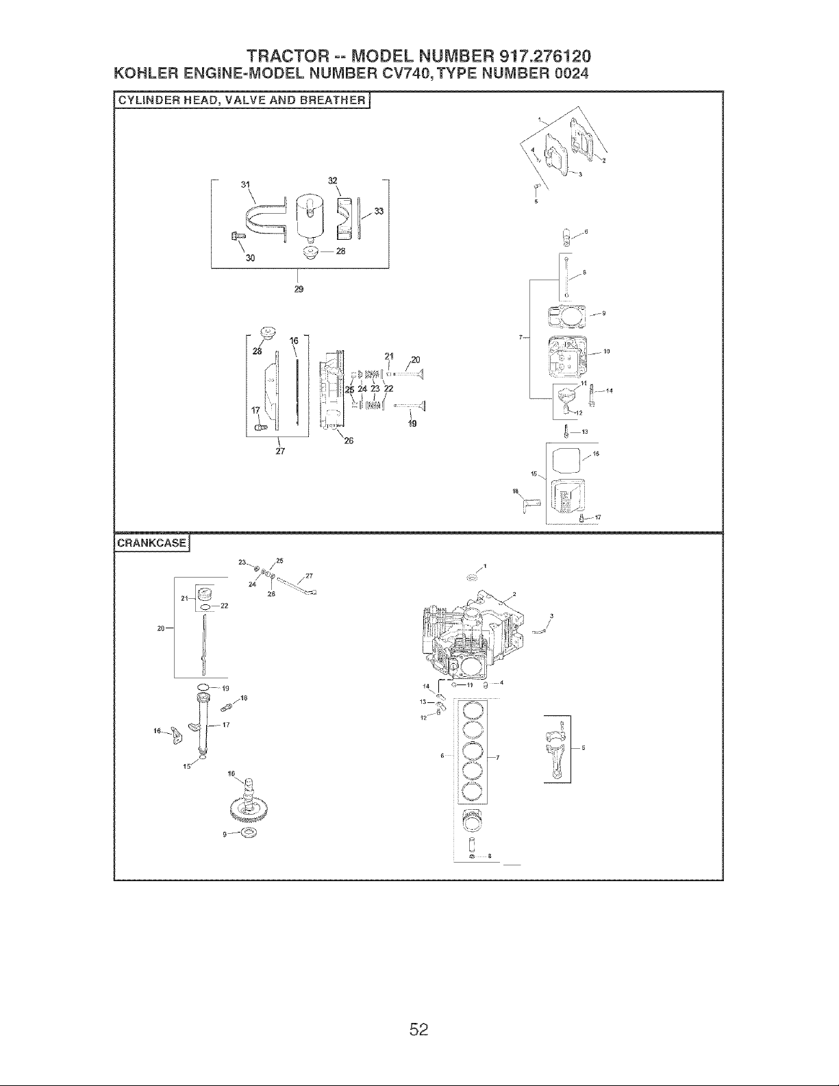
TRACTOR -- MODEL NUMBER 917.276120
KOHLER ENGmNE-MODEL NUMBER CV740, TYPE NUMBER 0024
CYUNDER HEAD_ VALVE AND BREATHER_
28 r_
I
_u
27
CRANKCASEJ
2O
C.,%-- 19
_ j18
16-_ -17'
18 j°
10
//1
i
ii _
]Y
°_ Ill
_ 8
52

TRACTOR °o MODEL NUMBER 917.276120
KOHLER ENGmNE=MODEL NUMBER CV740,TYPE NUMBER 0024
HEAD/VALVE!BREATHER
CRANKCASE
KEY PART KEY PART
NO. NO. DESCRIPTION NO. NO. DESCRIPTION
2,
3.
4.
5.
6.
7.
8.
9.
24-033-03-S Kit, breather cover w/gasket (Includes 1. 24-032-01-S
2-4) 2.
24-041-80-S Gasket, breather 3. 24-294-13-S
24-096-87-S Cover, breather 4. 24-380-13-S
25-!39-60-S Plug, allen hd. 1/8" 8. 24-067-13-S
M-648020-S Screw, hex. flange M6xl.0x20 (4) 24-067-14-S
28-351-01-S Lifter, valve (4) 8. 24-874-08-S
24-755-86-S Kit, valve train (includes 8,11,12)
24-411-05-S Rod, push (4) 24-874-18-S
24-841-03-S Kit, cylinder head gasket (Includes 28 24-874-20-S
072 04-S) (2) 24-874-21-S
24-318-72-S Kit, #2 cylinder head 7. 24-108-08-S
28-186-01-S Arm, rocker (4) 24-108-08-S
24-899-01-S Pivot, rocker arm (4) 24-108-07-S
66-086-07-S Screw, hex. flange M6xl.0x34 (4) 8. 24-018-01-S
12 086 16-S Screw, hex. flange M10x1.Sx90 (8) 9. 12-422-09-S
24-755-141-S Kit, valve cover - plain 12-422-13-S
12-422-07-S
(includes 16,17) 12-422-08-S
24-!53-28-S O-Ring 12-422-!0-S
M-651030-S Screw, hex. flange M6xl.0x30 (4) 12-422-!1-S
24-445-01-S Strap, lifting 12-422-12-S
24-016-01-S Valve, exhaust (Std.) (2) 10. 24-012-!8-S
24-016-02-S Valve, exhaust (.28) (2) 11. 52-139-09-S
24-017-01-S Valve, intake (Std.) (2) 12. M-848010-S
24-017-02-S Valve, intake (.25) (2) 13. 24-018-04-S
66-032-08-S Seal, valve stem (2) 14. 24-402-08-S
235011-S Retainer, spring (4) 18. 12-153-0!-S
24-089-02-S Spring, valve (4) 18. 24-126-!9-S
12-173-01-S Cap, valve spring (4) 17. 12-123-04-S
12-755-03-S Kit, retainer (4) 18. M-548016-S
24-318-69-S Kit, #1 cylinder head 19. 12-153-02-S
24-755-142-S Kit, valve cover - breather (Includes 20. 24-038-04-S
16,17,28) 21. 24-758-48-S
25-313-03-S Grommet, rubber 22. 28-153-02-S
24-755-87-S Kit, breather separator 23. 24-018-09-S
(includes 28,30-33) 24. M-931010-S
M-548018-S Screw, hex. flange M5x0.8x18 (2) 28. 28-032-09-S
24-448-02-S Strap, breather
28. 24-468-18-S
24-126-44-S Bracket, breather separator 27. 24-144-38-S
24-112-!2-S Spacer
24-326-85-S Rose, breather
10.
11.
12.
13.
14.
15.
16.
17.
18.
19.
20.
21.
22.
23.
24.
25.
26.
27.
28.
29.
30.
31.
32.
33.
34.
Seal, front oil
Crankcase (USE: Minib!ock 24 782 23)
Fitting
Pin, locating (8)
Connecting Rod (Std.) (2)
Connecting Rod (.28) (2)
Piston w/Ring Set (Std.) (2) (Includes
7,8)
Kit, Piston w/Ring Set (.08) (2)
Piston w/Ring Set (.28) (2)
Piston w/Ring Set (.80) (2)
Ring Set (Std. & .08) (2)
Ring Set (.28) (2)
Ring Set (.80) (2)
Retainer, piston pin (4)
Shim, camshaft (A.R.)
Shim, camshaft (A.R.)
Shim, camshaft (A.R.)
Shim, camshaft (A.R.)
Shim, camshaft
Shim, camshaft (A.R.)
Shim, camshaft (A.R.)
Camshaft
Plug, cup
Screw, hex. flange MSx0.8xl0 (2)
Retainer, reed (2)
Reed, breather (2)
O-Ring, lower oil fill tube
Bracket, oil fill tube
Tube, oil fill
Screw, hex. flange MSx0.8x18
O-Ring, upper oil fill tube
Dipstick assembly (Includes 21 22)
Kit, oil fill cap (Includes 22)
O-Ring, dipstick
Retainer, ring
Washer, nylon (top)
Sea!, governor cross shaft
Washer (bottom)
Shaft, governor cross
NOTE: All component dimensions given in U.S. inches
1 inch = 28.4 mm
53
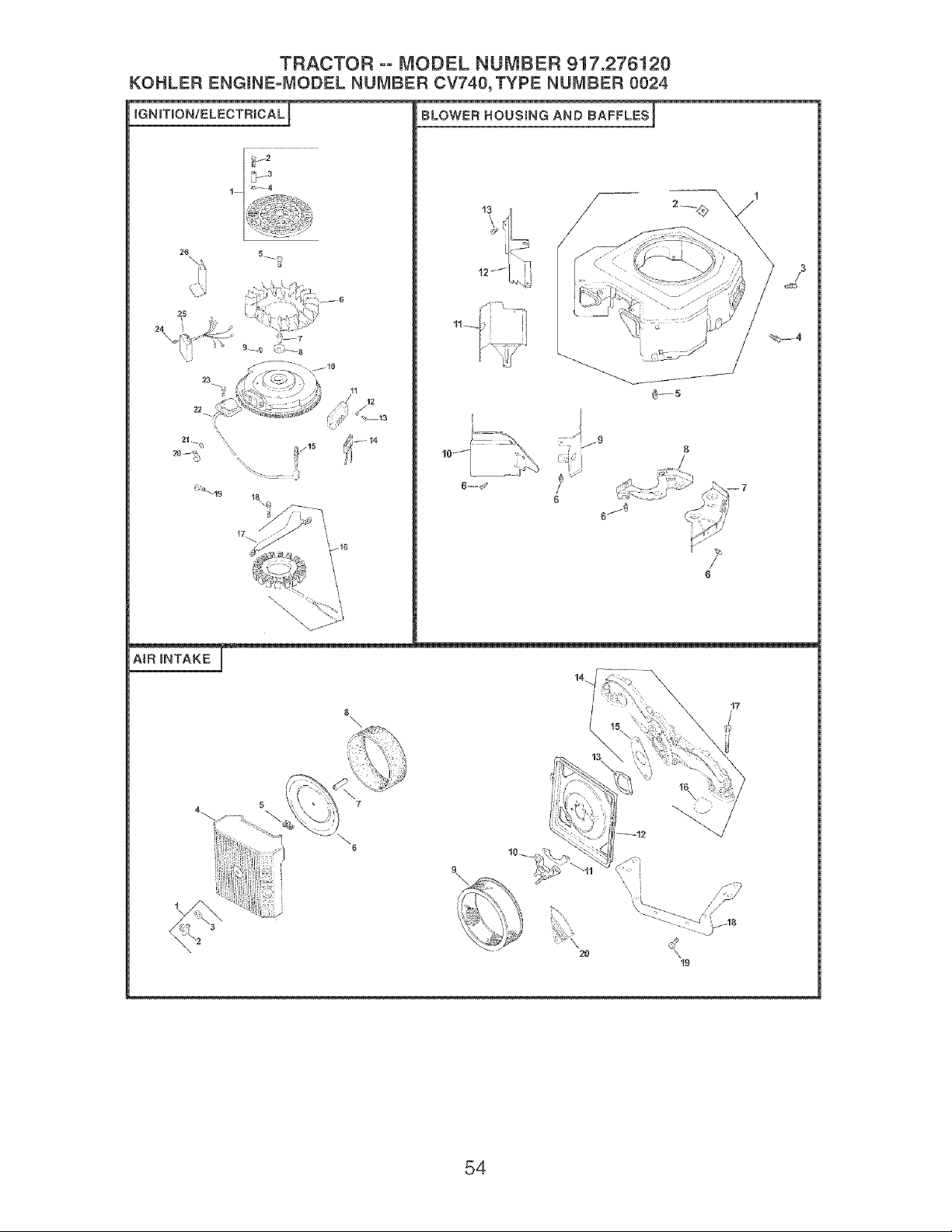
TRACTOR °° MODEL NUMBER 947.276120
KOHLER ENGINE=MODEL NUMBER CV740_ TYPE NUMBER 0024
iGNITION/ELECTRICALJ BLOWER HOUSING AND BAFFLES I
\
\
AiR iNTAKE r
14.
B\ / 17
'\ i
2O
54
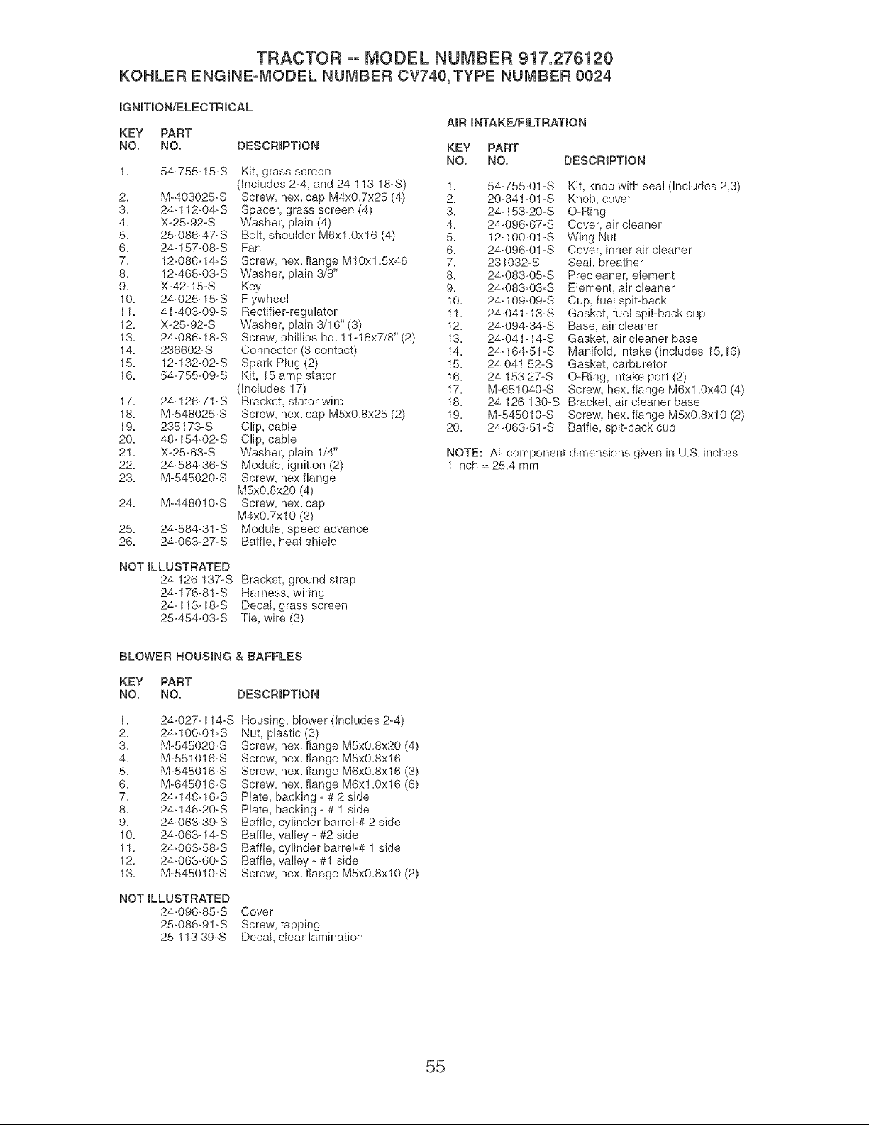
TRACTOR °° MODEL NUMBER 917.276120
KOHLER ENGmNE=mvmoDELNUMBER CV740,TYPE NUMBER 0024
IGNmON!ELECTRmCAL
KEY PART
NO. NO. DESCRIPTION
A_R INTAKE/FILTRATION
KEY PART
NO. NO.
1. 64-756=15=S Kit, grass screen
(includes 2-4, and 24 113 18=S) 1.
2. M=403025=S Screw, hex. cap M4x0.7x26 (4) 2.
3. 24-112-04-S Spacer, grass screen (4) 3.
4. X-25=92-S Washer, plain (4) 4.
6. 26-086-47-S Bolt, shoulder M6xl.0x16 (4) 5.
6. 24-157-08-S Fan 6.
7. 12-086=!4-8 Screw, hex. flange M10xl.Sx46 7.
8. 12-468-03=S Washer, plain 3/8" 8.
9. X-42-15-S Key 9.
10. 24-025-15-S Flywheel 10.
11. 41-403-09-S Rectifier=regulator 11.
12. X-25=92-S Washer, plain 3/16" (3) 12.
13. 24-086-18=S Screw, phillips hd. 11-16x7/8" (2) 13.
14. 236602-S Connector (3 contact) 14.
15. 12-132-02-S Spark Plug (2) 15.
16. 64-765-09=S Kit, 15 amp stator 16.
(includes 17) 17.
17. 24-126-71-S Bracket, stator wire 18.
18. M-648025-S Screw, hex. cap MSx0.8x26 (2) 19.
19. 235173=S Clip, cane 20.
20. 48_154-02-S Clip, cable
2!. X-25-63=S Washer, plain 1/4"
22. 24-684-36-S Module, ignition (2)
23. M-546020=S Screw, hex flange
MSx0.8x20 (4)
24. M-448010=S Screw, hex. cap
M4x0.7xl0 (2)
25. 24-584=31-S Module, speed advance
26. 24-063=27-S Baffle, heat shield
NOT ILLUSTRATED
24 126 137-S
24=176-81-S
24°113o18°S
25=464=03=S
Bracket, ground strap
Harness, wiring
Decal, grass screen
Tie, wire (3)
DESCRIPTmON
54-755-01-S
20-341-01-S
24q 53-20-S
24-096-67-S
12q00-01-S
24_096-01-S
231032=S
24_083-05=S
24-083-03-S
24_109-09-S
24-041 =13=S
24_094=34-S
24-041 =14- S
24_164=51-S
24 041 52-S
24 ! 53 27-S
M-661040-S
Kit, knob with seal (Includes 2,3)
Knob, cover
O-Ring
Cover, air cleaner
Wing Nut
Cover, inner air cleaner
Seal, breather
Precleaner, element
Element, air cleaner
Cup, fuel spit-back
Gasket, fuel spit-back cup
Base, air cleaner
Gasket, air cleaner base
Manifold, intake (includes 16,16)
Gasket, carburetor
O-Ring, intake port (2}
Screw, hex. flange M6x1.0x40 (4)
24 126 !30-S Bracket, air cleaner base
M-545010-S Screw, hex. flange M5x0.8xl0 (2)
24-063-61-S Baffle, spit-back cup
NOTE: All component dimensions given in U.S. inches
1 inch = 26.4 mm
BLOWER HOUSING & BAFFLES
KEY PART
NO. NO. DESCRIPTmON
1. 24=027-114-S
2. 24-100-0!-S
3. M-645020-S
4. M-551016 S
5. M-645016-S
6. M-645016-S
7. 24=146-16=S
8. 24-146-20-S
9. 24-063°39-S
10. 24=063-14-S
11. 24-063-58-S
12. 24-063-60-S
13. M_645010=S
Housing, blower (Includes 2-4)
Nut, plastic (3)
Screw, hex. flange M6xO.8x20 (4)
Screw hex. flange MSxO.8x16
Screw hex. flange M6xO.8x16 (3)
Screw hex. flange M6x1.0x16 (6)
Plate backing - # 2 side
Plate backing - # 1 side
Baffle cylinder barrel-# 2 side
Baffle valley - #2 side
Baffle cylinder barrel-# 1 side
Baffle valley - #1 side
Screw, hex. flange M5xO.8xlO (2)
NOT ILLUSTRATED
24=096-85-S
25-086-91-S
25 113 39-S
Cover
Screw, tapping
Decal, clear lamination
55
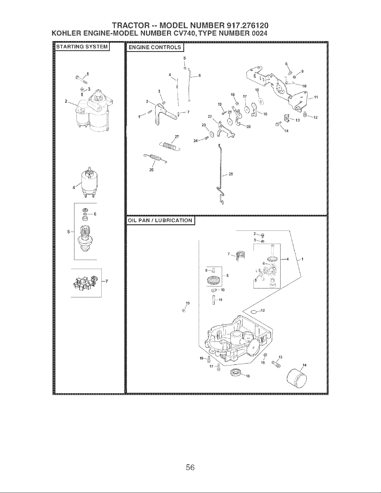
TRACTOR ooMODEL NUMBER 917.276120
KOHLER ENGmNE=MODEL NUMBER CV740, TYPE NUMBER 0024
5-
@
6
ENGINE CONTROLS
27
22
\
/ 25
OraL PAN 1 LUBRICATmON ]
19
3_ O
56
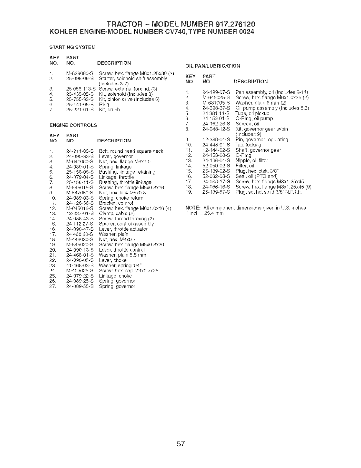
TRACTOR oo MODEL NUMBER 917.276120
KOHLER ENGmNE-IVIODEL NUMBER CV740,TYPE NUMBER 0024
STARTING SYSTEM
KEY PART
NO. NO. DESCRmPTmON
3.
4.
5.
6.
7.
M-839080-S Screw, hex. flange M8xl.25x80 (2)
25-098-09-S Starter, solenoid shift assembly
(Includes 3-7)
25 086 113-S Screw, external torx hd. (3)
25-435-05-S Kit, solenoid (Includes 3)
25-755-33-S Kit, pinion drive (Includes 6)
25-141-05-S Ring
25-221-01-S Kit, brush
ENGINE CONTROLS
KEY PART
NO. NO. DESCRmPTmON
1.
2.
3.
4.
5.
6.
7.
8.
9.
10.
11.
12.
13.
14.
15.
16.
17.
18.
19.
20.
21.
22.
23.
24.
25.
26.
27.
24-211-03-S
24-090-33-S
M-641060-S
24-089-01 -S
25-158-08-S
24-079-04-S
25-158-11 -S
M-545016-S
M-547050-S
24-089-03-S
24-126-56-S
M-645016-S
12-237-01-S
24-086-43-S
24 112 27-S
24-090-47-S
24 468 20-S
M-446030-S
M-545020-S
24-090-13-S
24-468-01 -S
24-090-05-S
41-468-03-S
M-403025-S
24-079-22-S
24-089-25-S
24-089-55-S
Bolt, round head square neck
Lever, governor
Nut, hex. flange M6x1.0
Spring, linkage
Bushing, linkage retaining
Linkage, throttle
Bushing, throttle linkage
Screw, hex. flange M5xO.8x16
Nut, hex. lock M5xO.8
Spring, choke return
Bracket, control
Screw, hex. flange M6x1.0x16 (4)
Clamp, cable (2)
Screw, thread forming (2)
Spacer, control assembly
Lever, throttle actuator
Washer, plain
Nut, hex. M4xO.7
Screw, hex. flange M5xO.8x20
Lever, throttle control
Washer, plain 5.5 mm
Lever, choke
Washer, spring 1/4"
Screw, hex. cap M4xO.7x25
Linkage, choke
Spring, governor
Spring, governor
OIL PAN/LUBRmCATION
KEY PART
NO. NO. DESCRmPTION
1. 24q99-O7-S Pan assembly, oil (Includes 2ql)
2. M-645028-S Screw, hex. flange M6x1.0x25 (2)
3. M-631008-S Washer, plain 6 mm (2)
4. 24_393-37_S Oil pump assembly (includes 5,6)
5. 24 381 11-S Tube, oil pickup
6. 24 153 01-S O_Ring, oil pump
7. 24q62-26_S Screen, oil
8. 24_043-12-S Kit, governor gear w/pin
(Includes 9)
9. 12-380-01-S Pin, governor regulating
10. 24-448-01-S Tab, locking
11. 12-144-02-S Shaft, governor gear
12. 24q 53-08-S O-Ring
13. 24q36-01-S Nipple, oil filter
14. 52-050-02-S Filter, oil
15. 25q39-62-S Plug, hex. ctsk. 3/8"
16. 52_032-08_S Sea!, oil (PTO end)
17. 24-086-17-S Screw, hex. flange M8x1.25x48
18. 24-086-16-S Screw, hex. flange M8x1.25x45 (9)
19. 25q39-57-S Plug, sq. hd. solid 3/8" N.RT.R
NOTE: All component dimensions given in U.S. inches
1 inch = 25.4 mm
57
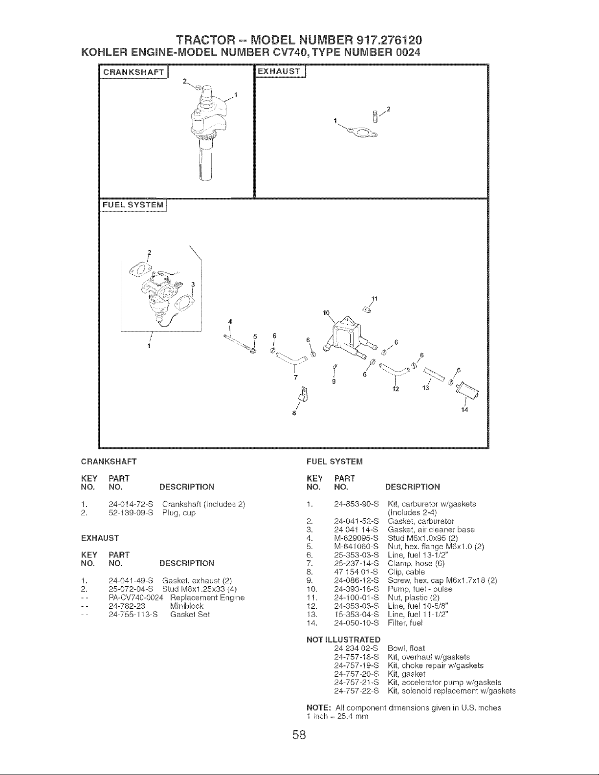
TRACTOR ooMODEL NUMBER 917.276120
KOHLER ENGmNE=MODELNUMBERCV740,TYPE NUMBER0024
CRANKSHAFT i
EXHAUST i
_j2
FUEL SYSTEM J
\
11
5 6
t
6
\
9
14
CRANKSHAFT FUEL SYSTEM
KEY PART KEY PART
NO. NO. DESCRmPTmON NO. NO. DESCRIPTION
1. 24-014-72-S Crankshaft (Includes 2)
2= 52-139-09-S Plug, cup
EXHAUST
KEY PART
NO. NO. DESCRmPTmON
1=
2,
24-041-49-S Gasket, exhaust (2)
25-072-04-S Stud M8x1.25x33 (4)
PA-CV740-O024 Replacement Engine
24-782-23 Miniblock
24-755-113-S Gasket Set
1. 24-853-90-S Kit, carburetor w/gaskets
(Includes 2-4)
2. 24-041-52-S Gasket, carburetor
3. 24 041 14-S Gasket, air cleaner base
4. M-629095-S Stud IV]6x1.0x95 (2)
5. M-641060-S Nut, hex=flange M6xl=0 (2)
6. 25-353-03-S Line, fuel 13-1/2"
7. 25-237-14-S Clamp, hose (6)
8. 47 154 01-S Clip, cable
9. 24-086-12-S Screw, hex. cap M6xl.7x18 (2)
10. 24-393-16-S Pump, fuel- pulse
11. 24-100-01-S Nut, plastic (2)
12= 24-353-03-S Line, fue! 10-5/8"
13= 15-353-04-S Line, fue! 11-1/2"
14. 24-050-10-S Filter, fuel
NOT iLLUSTRATED
24 234 02-S
24-757-18-S
24-757-19-S
24-757-20-S
24-757-2! -S
24-757-22-S
Bowl, float
Kit, overhaul w/gaskets
Kit, choke repair w/gaskets
Kit, gasket
Kit, accelerator pump w/gaskets
Kit, solenoid replacement w/gaskets
NOTE: All component dimensions given in U.S. inches
1 inch = 25=4 mm
58

SUGGESTED GUIDE FOR SIGHTING SLOPES FOR SAFE OPERATION
ONLY RIDE UP AND DOWN HILL,
NOT ACROSS HILL
15 DEGREES MAX.
_hb ARNING: To avoid serious injury, operate your tractor up and
down the face of slopes, never across the face. Do not mow
slopes greater than 15 degrees. Make turns gradually to prevent
tipping or loss of control. Exercise extreme caution when
changing direction on slopes.
1. Fold this page along dotted line indicated above,
2. Hold page before you so that its left edge is vertically parallel to a tree
trunk or other upright structure.
3. Sight across the fomd in the direction of hi[[ slope you want to measure.
4. Compare the angle of the fo_d with the slope of the hill

iiiiiiiiiiiiiiiii_
Your Home
For repair - in your home - of all major brand appliances,
lawn and garden equipment, or heating and cooling systems,
no matter who made it, no matter who sold it!
For the replacement parts, accessories and
owner's manuals that you need to do-it-yourself.
For Sears professional installation of home appliances
and items like garage door openers and water heaters.
1-800-4-MY-HOME ® Anytime, day or night
(1-800-469-4663) (U.S.A. and Canada)
www.sears.com www.sears.ca
Our Home
For repair of carry-in products like vacuums, lawn equipment,
and electronics, call or go on-line for the nearest
Sears Parts and Repair Center.
1-800-488-1222 Anytime, day or night (U.S.A. only)
www.sears.com
!i!i!i!i!i!i!i!i!i!i!i!i!i!i!i!i!i!i!iii_
iiiiiiiiiiiiiiiiiiii
iiiiiiiiiiiiiiiiiiii
iiiiiiiiiiiiiiiiiiii
iiiiiiiiiiiiiiiiiiii
iiiiiiiiiiiiiiiiiiii
iiiiiiiiiiiiiiiiiiii
iiiiiiiiiiiiiiiiiiii
iiiiiiiiiiiiiiiiiiii
iiiiiiiiiiiiiiiiiiii
iiiiiiiiiiiiiiiiiiii
iiiiiiiiiiiiiiiiiiii
iiiiiiiiiiiiiiiiiiii
iiiiiiiiiiiiiiiiiiii
iiiiiiiiiiiiiiiiiiii
iiiiiiiiiiiiiiiiiiii
iiiiiiiiiiiiiiiiiiii
iiiiiiiiiiiiiiiiiiii
iiiiiiiiiiiiiiiiiiii
To purchase a protection agreement (U.S.A.)
or maintenance agreement (Canada) on a product serviced by Sears:
1-800-827-6655 (U.S.A.) 1-800-361-6665 (Canada)
Para pedir servicio de reparaci6n
a domicilio, y para ordenar piezas:
1-888-SU-HOGAR SM
(1-888-784-6427)
Au Canada pour service en frangais:
1-800-LE-FOYER Mc
(1-800-533-6937)
www.sears.ca
© Sears, RoebuckandCo.
® Registered Trademark / TMTrademark / SMService Mark of Sears, Roebuck and Co.
® Marca Registrada / TMMarca de F,_brica / SMMarca de Servicio de Sears, Roebuck and Co.
MCMarque de commerce / MDMarque deposee de Sears, Roebuck and Co.
191134 Rev. 3 6.14.04 MH Printed in U.S.A.


