Loading ...
Loading ...
• Never stand on tool. Serious injury could occur if tool
is tipped or if belt or disc are unintentionally contacted.
• Know your tool. Learn the tool's operation, applica-
tion and specific limitations,
• Use recommended accessories (refer to page 13).
Use of improper accessories may cause risk of
injury to persons.
• Handle workpiece correctly. Protect hands from pos-
sible injury.
• Turn machine off if it jams. Belt jams when it digs too
deeply into workpiece. (Motor force keeps it stuck in
the work.)
• Support workpiece with miter gauge, belt platen,
work stop or work table.
• Maintain '/_6"maximum clearance between table and
sanding belt or disc.
CAUTION; Think safety! Safety is a combination of
operator common sense and alertness at all times
when tool is being used.
WARNING; Do not attempt to operate tool until it is
completely assembled according to the instructions.
ATTACH ABRASIVE DISC TO ALUMINUM
I
DISC
Refer to Figure 2.
• Remove dust chute by looseningscrews and bolts,
• Remove the adhesive cover from the backof the
abrasive disc,
• Center abrasiveon aluminumdisc and press to paste.
• Make sure abrasiveis pasted evenly on thealuminum
disc.
• Replace dust chute
i
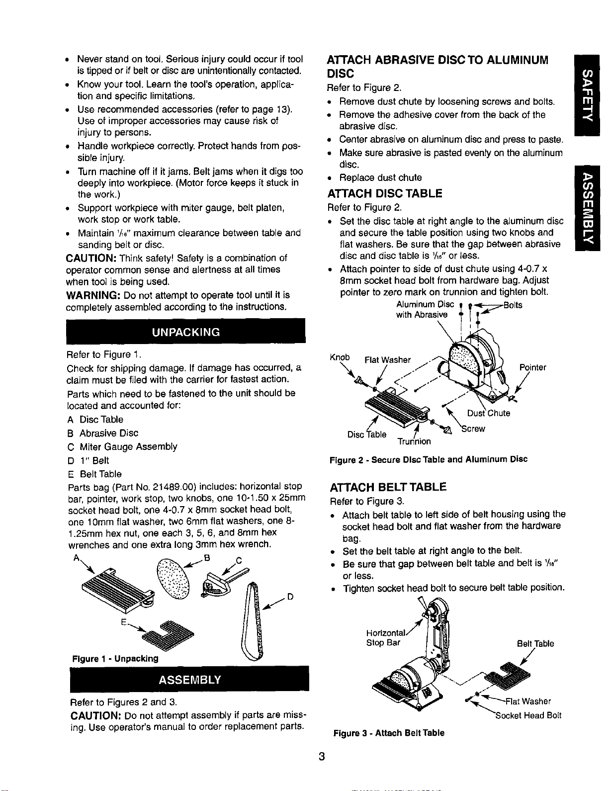
ATTACH DISC TABLE
Refer to Figure 2,
• Set the disc table at right angle to the aluminumdisc
and secure the table positionusing two knobsand
flatwashers. Be sure that the gap between abrasive
disc and disc table is _/_6"or less.
• Attach pointerto side of dust chute using4-0,7 x
8mm socket head boltfrom hardware bag.Adjust
pointerto zero mark on trunnionand tighten bolt.
AluminumDisc
withAbrasive
Refer to Figure 1.
Check for shipping damage. If damage has occurred, a
claim must be filed with the carrier for fastest action.
Parts which need to be fastened to the unit should be
located and accounted for:
A Disc Table
B Abrasive Disc
C Miter Gauge Assembly
D 1" Belt
E Belt Table
Parts bag (Part No. 21489.00) includes: horizontal stop
bar, pointer, work stop, two knobs, one 10-1.50 x 25mm
socket head bolt, one 4-0.7 x 8mm socket head bolt,
one 10mm flat washer, two 6mm flat washers, one 8-
1.25mm hex nut, one each 3, 5, 6, and 8ram hex
wrenches and one extra long 3mm hex wrench.
A -- .dc.--B C
Figure 1 - Unpacking
Knob FlatWasher .-"
_'X :Chute
Disc'_able T_Jion "_8_ "Screw
Pointer
Figure 2 - Secure Disc Table and Aluminum Disc
ATTACH BELT TABLE
Refer to Figure 3,
• Attach belt table to leftside of belt housingusingthe
socket head boltand flat washer from the hardware
bag.
• Set the belt table at right angle to the belt.
• Be sure that gap between belt table and belt is '/16"
or less.
• Tighten socket head bolt to secure belt table position.
Stop Bar Belt Table
Refer to Figures 2 and 3.
CAUTION: Do not attempt assembly if parts are miss-
ing. Use operator's manual to order replacement parts.
Figure 3 - Attach Belt Table
Head Bolt
3
Loading ...
Loading ...
Loading ...