
Operator's Manual I
x 42" Belt
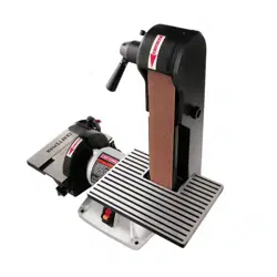
SANDER
Model No.
351.215130
Sears, Roebuck and Co., Hoffman Estates, IL 60179 U.S.A.
www.sears.com/craftsman
20067.01 Draft (11/07/03)
Warranty.................................... 2
SafetyRules............................... 2-3
Unpacking.................................. 3
Assembly................................. 3-4
Installation................................. 4-5
Operation................................. 5-8
Maintenance............................... 8-9
Troubleshooting............................. 10
PartsIllustrationandList................... 12-13
EspaScl................................. 14-22
FULL ONE YEAR WARRANTY
If this product fails due to a defect in material or work-
manship within one year from the date of purchase,
Sears willat itsoption repair or replace it free of
charge. Contact your nearest Sears Service Center
(1-800-4-MY-HOME) to arrange for productrepair, or
return this productto place of purchase for replace-
ment.
If this product is used for commercial or rental purpos-
es, this warranty will apply for 90 days from the date of
purchase,
This warranty applies only while this product is used in
the United States.
This warranty gives you specific legal rights and you
may also have other dghts which vary from state to
state.
Sears, Roebuck and Co., Dept. 817WA, Hoffman
Estates, IL 60179
WARNING: For your own safety, read all of the
instructions and precautions before operating tool.
CAUTION: Always follow proper operating procedures
as defined in this manual even if you are familiar with
use of this or similar tools. Remember that being care-
less for even a fraction of a second can result in severe
personal injury.
BE PREPARED FOR JOB
• Wear proper apparel. Do not wear loose clothing,
gloves, neckties, rings, bracelets or other jewelry
which may get caught in moving parts of machine.
• Wear protective hair covering to contain long hair.
• Wear safety shoes with non-slip soles.
• Wear safety glasses complying with United States
ANSI Z87.1. Everyday glasses have only impact
resistant lenses. They are NOT safety glasses.
• Wear face mask or dust mask if operation is dusty.
• Be alert and think clearly. Never operate power tools
when tired, intoxicatedor when taking medications
that cause drowsiness.
PREPARE WORK AREA FOR JOB
• Keep work area ciean. Cluttered work areas invite
accidents.
• Do not use power tools in dangerous environments.
Do not use powertools in damp or wet locations.Do
not expose powertools to rain.
• Work area should be properly lighted.
• Proper electrical receptacle shouldbe available for
tool.Three-prong plugshould be pluggeddirectly
intoproperly grounded, three-prong receptacle,
• Extension cords shouldhave a groundingprongand
the three wires of the extension cordshould be of
the correctgauge.
• Keep visitorsat a safe distance from work area.
• Keep children out of workplace. Make workshop
childproof.Use padlocks,master switches or remove
switchkeysto preventany unintentionaluse of
power tools.
TOOL SHOULD BE MAINTAINED
• Always unplug tool prior to inspection.
• Consult manual for specificmaintaining and adjust-
ing procedures.
• Keep tool lubricated and clean for safest operation.
• Remove adjustingtools. Form habit of checkingto
see that adjustingtools are removed before switch-
ingmachine on.
• Keep all parts in working order.Check to determine
thatthe guard or other parts willoperate properly
and perform their intendedfunction.
• Check for damaged parts. Check for alignmentof
moving parts, binding, breakage, mountingand any
other condition that may affect a tool'soperation.
• A guard or other part that is damaged shouldbe
properlyrepaired or replaced. Do not perform
makeshift repairs. (Use parts list provided to order
replacement parts.)
KNOW HOW TO USE TOOL
• Use righttool for job. Do not force tool or attachment
to do a job for which it was not designed.
• Disconnecttool when changing belt or abrasive disc.
• Avoid accidental start-up. Make sure that the switch
is in the "OFF" positionbefore plugging in.
• Do not force tool. It willwork most efficientlyat the
ratefor whichit was designed.
• Keep hands away from moving parts and sanding
surfaces.
• Never leave tool running unattended. Turn the power off
and do not leave tool until it comes to a complete stop.
• Do not overreach. Keep proper footing and balance.
© Sears, Roebuck and Co. 2
• Never stand on tool. Serious injury could occur if tool
is tipped or if belt or disc are unintentionally contacted.
• Know your tool. Learn the tool's operation, applica-
tion and specific limitations,
• Use recommended accessories (refer to page 13).
Use of improper accessories may cause risk of
injury to persons.
• Handle workpiece correctly. Protect hands from pos-
sible injury.
• Turn machine off if it jams. Belt jams when it digs too
deeply into workpiece. (Motor force keeps it stuck in
the work.)
• Support workpiece with miter gauge, belt platen,
work stop or work table.
• Maintain '/_6"maximum clearance between table and
sanding belt or disc.
CAUTION; Think safety! Safety is a combination of
operator common sense and alertness at all times
when tool is being used.
WARNING; Do not attempt to operate tool until it is
completely assembled according to the instructions.
ATTACH ABRASIVE DISC TO ALUMINUM
I
DISC
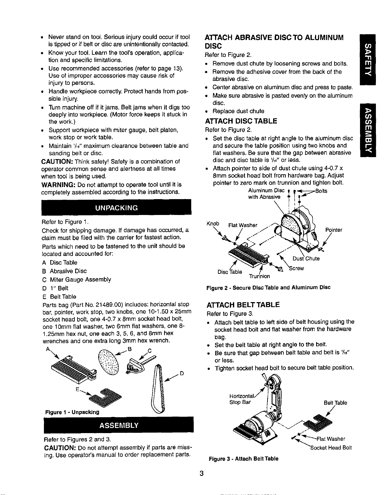
Refer to Figure 2.
• Remove dust chute by looseningscrews and bolts,
• Remove the adhesive cover from the backof the
abrasive disc,
• Center abrasiveon aluminumdisc and press to paste.
• Make sure abrasiveis pasted evenly on thealuminum
disc.
• Replace dust chute
i
ATTACH DISC TABLE
Refer to Figure 2,
• Set the disc table at right angle to the aluminumdisc
and secure the table positionusing two knobsand
flatwashers. Be sure that the gap between abrasive
disc and disc table is _/_6"or less.
• Attach pointerto side of dust chute using4-0,7 x
8mm socket head boltfrom hardware bag.Adjust
pointerto zero mark on trunnionand tighten bolt.
AluminumDisc
withAbrasive
Refer to Figure 1.
Check for shipping damage. If damage has occurred, a
claim must be filed with the carrier for fastest action.
Parts which need to be fastened to the unit should be
located and accounted for:
A Disc Table
B Abrasive Disc
C Miter Gauge Assembly
D 1" Belt
E Belt Table
Parts bag (Part No. 21489.00) includes: horizontal stop
bar, pointer, work stop, two knobs, one 10-1.50 x 25mm
socket head bolt, one 4-0.7 x 8mm socket head bolt,
one 10mm flat washer, two 6mm flat washers, one 8-
1.25mm hex nut, one each 3, 5, 6, and 8ram hex
wrenches and one extra long 3mm hex wrench.
A -- .dc.--B C
Figure 1 - Unpacking
Knob FlatWasher .-"
_'X :Chute
Disc'_able T_Jion "_8_ "Screw
Pointer
Figure 2 - Secure Disc Table and Aluminum Disc
ATTACH BELT TABLE
Refer to Figure 3,
• Attach belt table to leftside of belt housingusingthe
socket head boltand flat washer from the hardware
bag.
• Set the belt table at right angle to the belt.
• Be sure that gap between belt table and belt is '/16"
or less.
• Tighten socket head bolt to secure belt table position.
Stop Bar Belt Table
Refer to Figures 2 and 3.
CAUTION: Do not attempt assembly if parts are miss-
ing. Use operator's manual to order replacement parts.
Figure 3 - Attach Belt Table
Head Bolt
3
ATI'ACH HORIZONTAL STOP
Refer to Figure 3, page 3.
A horizontal stop bar with nut isprovided as a positive
stop when using the sander with the belt housing
adjusted to a horizontal position. To attach stop bar:
• Thread the horizontal stop bar into the threaded hole
on the rear side of belt housing.
• Tighten hex nut.
Refer to Figures 4, 5 and 6, pages 4 and 5.
POWER SOURCE
WARNING: Do not connectsander to the powersource
untilall assemblysteps have been completed.
The motor is designed for operation on the voltage and
frequency specified. Normal loads will be handled safely
on voltages not more than 10% above or below speci-
fied voltage. Running the unit on voltages which are not
within range may cause overheatingand motor burn-
out. Heavy loads require that voltage at motor terminals
be no less than the voltage specified on nameplate.
• Power supply to the motor is controlled by a single
pole locking rocker switch. Remove the key to pre-
vent unauthorized use.
GROUNDING INSTRUCTIONS
WARNING: improper connection of equipment
grounding conductor can result in the risk of electrical
shock. Equipment should be grounded while in use to
protect operator from electrical shock.
• Check with a qualified electrician if grounding
instructions are not understood or if in doubt as to
whether the tool is properly grounded.
• This tool is equipped with an approved 3--conductor
cord rated at 300V and a 3-prong grounding type
plug (see Figure 4) for your protection against shock
hazards.
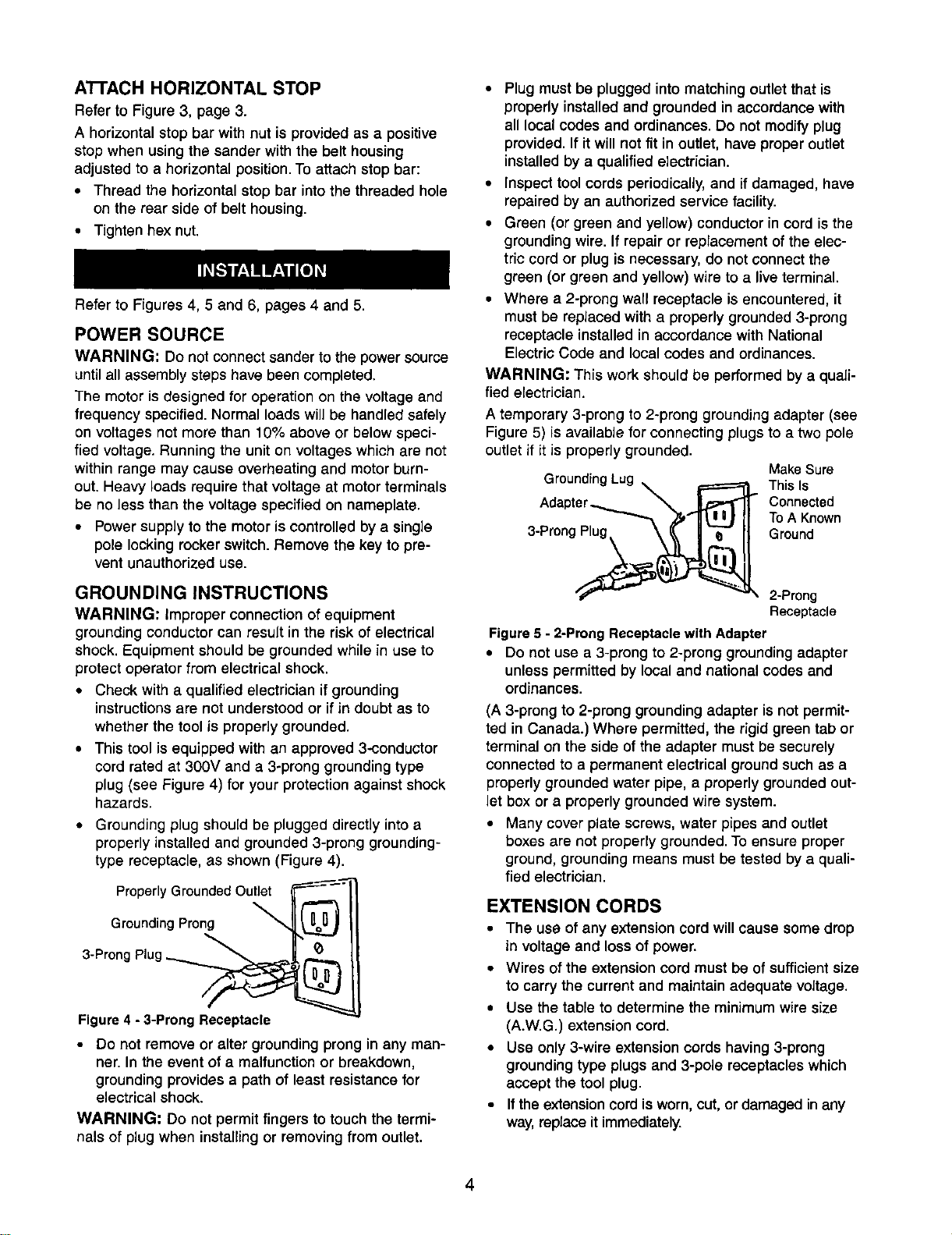
• Grounding plug should be plugged directly into a
properly installed and grounded 3-prong grounding-
type receptacle, as shown (Figure 4).
Properly Grounded Outlet
Grounding Prong
3-Prong Plug _._
Figure 4 - 3-Prong Receptacle
• Do not remove or alter grounding prong in any man-
ner. In the event of a malfunction or breakdown,
grounding provides a path of least resistance for
electrical shock.
WARNING: Do not permit fingers to touch the termi-
nals of plug when installingor removingfrom outlet.
• Plug must be plugged into matching outlet that is
properly installed and grounded in accordance with
all local codes and ordinances. Do not modify plug
provided. If it will not fit in outlet, have proper outlet
installed by a qualified electrician.
• Inspect tool cords periodically, and ifdamaged, have
repaired by an authorized service facility.
• Green (or green and yellow) conductor in cord is the
grounding wire. If repair or replacement of the elec-
tric cord or plug is necessary, do not connect the
green (or green and yellow) wire to a live terminal.
• Where a 2-prong wall receptacle is encountered, it
must be replaced with a properly grounded 3-prong
receptacle installed in accordance with National
Electric Code and local codes and ordinances.
WARNING: This work should be performed by a quali-
fied electrician.
A temporary 3-prong to 2-prong grounding adapter (see
Figure 5) is available for connecting plugs to a two pole
outlet if it is properly grounded.
MakeSure
GroundingLug _ F====_ This Is
Connected
I
To A Known
3-Prong Plug. \ _ | "-_ II Ground
__ 2-Prong
Receptacle
Figure5 - 2-ProngReceptaclewith Adapter
• DOnot use a 3-prong to 2-prong groundingadapter
unlesspermitted by local and nationalcodes and
ordinances.
(A 3-prong to 2-prong grounding adapter is not permit-
ted in Canada.) Where permitted, the rigid green tab or
terminal on the side of the adapter must be securely
connected to a permanent electrical ground such as a
properly grounded water pipe, a properly grounded out-
let box or a properly grounded wire system.
• Many cover plate screws, water pipes and outlet
boxes are not properly grounded. To ensure proper
ground, grounding means must be tested by a quali-
fied electrician.
EXTENSION CORDS
• The use of any extension cord will cause some drop
in voltage and lossof power.
• Wires of the extension cord must be ofsufficientsize
to carry the current and maintain adequate voltage.
• Use the table to determine the minimum wire size
(A.W.G.) extension cord.
• Use only3-wire extension cords having 3-prong
groundingtype plugsand 3-pole receptacleswhich
accept the tool plug.
• If theextensioncord isworn, cut, ordamaged inany
way,replace itimmediately.
4
Extension Cord Length
Wire Size............................... A,W.G.
Up to 25 ft.................................. 18
NOTE: Using extension cords over 25 ft. long is not
recommended.
MOTOR
The sander is assembled with motorand wiring
installedas an integralpart ofthe tool.The electrical
wiringschematic is shown in Figure 6.
The permanently splitcapacitor motor has the following
specifications:
Horsepower (Maximum Developed) .............. 2/3
Voltage ............................... 120/240
Amps................................. 3.5/1.75
Hertz ..................................... 60
Phase .................................. Single
RPM .................................... 3500
Rotation (viewed from leftside) ........... Clockwise
ELECTRICAL CONNECTIONS
WARNING: All electrical connections must be per-
formed by a qualified electrician. Make sure tool is off
and disconnected from power source while motor is
mounted, connected, reconnected or anytime wiring is
inspected.
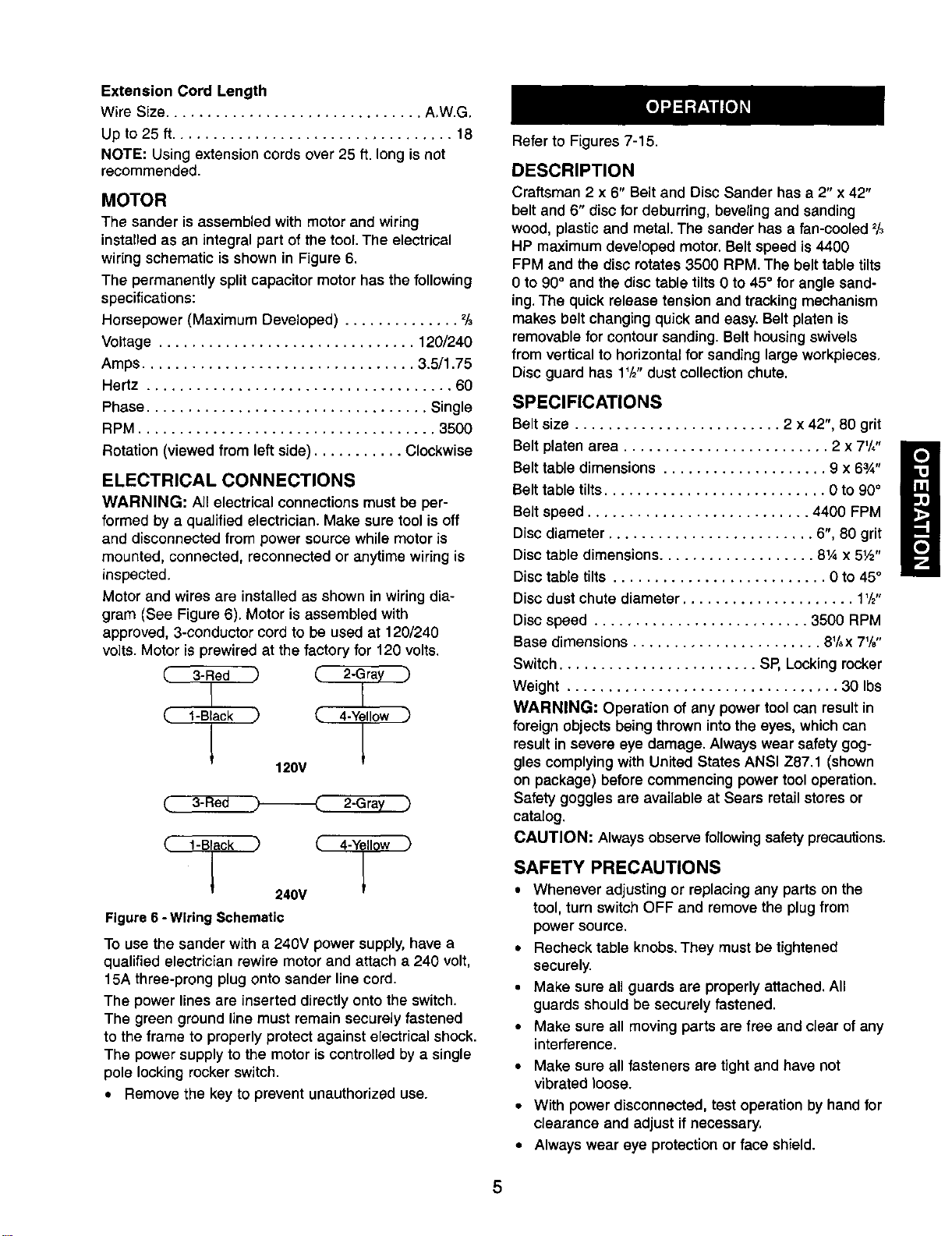
Motor and wires are installed as shown in wiring dia-
gram (See Figure 6). Motor is assembled with
approved, 3-conductor cord to be used at 120/240
volts. Motor is prewired at the factory for 120 volts.
(.. l-Black ,) (_ 4-Yellow )
120V
3- e 2-Gra
( l-Black _
240V
Figure 6 -Wiring Schematic
To use the sander with a 240V power supply,have a
qualified electrician rewire motor and attach a 240 volt,
15A three-prong plug onto sander line cord.
The power lines are inserted directly onto the switch.
The green ground line must remain securely fastened
to the frame to properly protect against electrical shock.
The power supply to the motor is controlled by a single
pole locking rocker switch.
• Remove the key to prevent unauthorized use.
Refer to Figures 7-15.
DESCRIPTION
Craftsman 2 x 6" Belt and Disc Sander has a 2" x 42"
belt and 6" disc for deburring, beveling and sanding
wood, plastic and metal. The sander has a fan-cooled 2/3
HP maximum developed motor. Belt speed is 4400
FPM and the disc rotates 3500 RPM. The belt table tilts
0 to 90° and the disc table tilts 0 to 45° for angle sand-
ing. The quick release tension and tracking mechanism
makes belt changing quick and easy. Belt platen is
removable for contour sanding. Belt housing swivels
from vertical to horizontal for sanding large workpieces.
Disc guard has 1'/2"dust collection chute.
SPECIFICATIONS
Belt size ......................... 2 x 42", 80 grit
Belt platen area ......................... 2 x 7'/,"
Belt table dimensions .................... 9 x 63_"
Belt table tilts........................... 0 to 90°
Belt speed ........................... 4400 FPM
Disc diameter ......................... 6", 80 grit
Disc table dimensions ................... 81,4x 5W'
Disc table tilts .......................... 0 to 45°
Disc dust chute diameter ..................... 1'/2"
Disc speed .......................... 3500 RPM
Base dimensions ....................... 81/,x 71/8"
Switch ........................ SP, Locking rocker
Weight ................................. 30 Ibs
WARNING: Operation of any power tool can result in
foreign objects being thrown into the eyes, which can
result in severe eye damage. Always wear safety gog-
gles complying with United States ANSI Z87.1 (shown
on package) before commencing power tool operation.
Safety goggles are available at Sears retail stores or
catalog.
CAUTION: Always observe following safetyprecautions.
SAFETY PRECAUTIONS
• Whenever adjusting or replacing any parts on the
tool, turn switchOFF and remove the plugfrom
power source.
• Recheck table knobs.They mustbe tightened
securely.
• Make sure all guards are properly attached. All
guards shouldbe securely fastened.
• Make sure all moving parts are free and clear of any
interference.
• Make sure all fasteners are tight and have not
vibrated loose.
• With power disconnected, test operation by hand for
clearance and adjust if necessary,
• Always wear eye protection or face shield.
5
• Make sure abrasive belt always tracks properly.
Correct tracking gives optimum performance.
• After turning switch on, always allow belt to come up
to full speed before sanding or grinding.
• Be sure motor runs clockwise on disc side. Abrasive
belt must travel down.
• Avoid kickback by sanding in accordance with the
directional arrows.
• Keep your hands clear of abrasive belt, disc and all
moving parts.
• For optimum performance, do not stall motor or
reduce speed. Do not force the work into the abrasive.
• Support workpiece with belt table when sanding with
belt, with disc table when sanding with disc.
• Never push a sharp corner of the workpiece rapidly
against the belt or disc. Abrasive backing may tear.
• Replace abrasives when they become loaded
(glazed) or frayed.
• When grinding metal, move workpiece across abra-
sive to prevent heat buitt up.
• Never attempt wet sanding. If the workpiece
becomes too hot to handle, cool it in water.
MOUNT SANDER
During operation the sander may have a tendency to slide
or move about on the bench or table. It is recommended
to mount the sander onto a stand (see "Recommended
Accessories", page 13) or to a bench top.
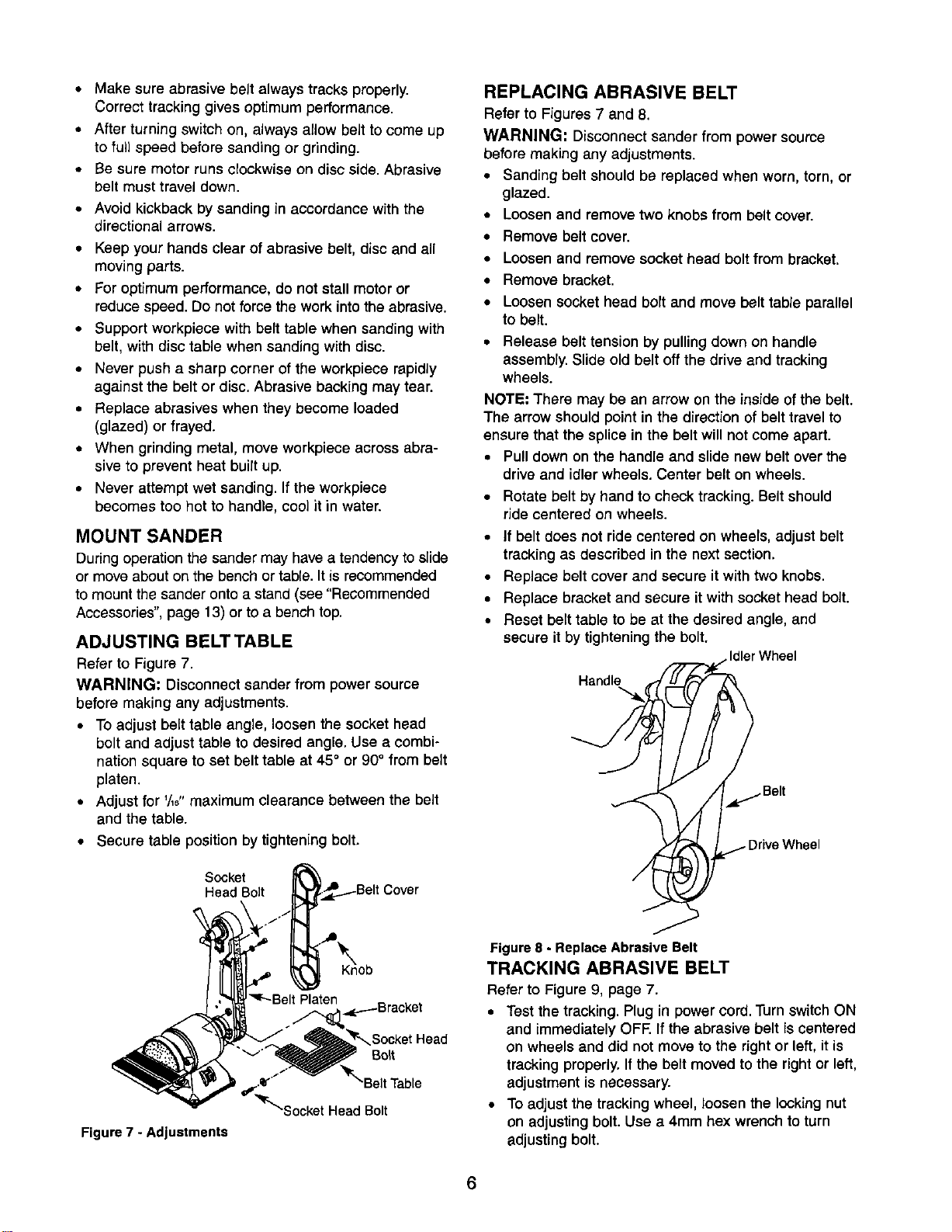
ADJUSTING BELT TABLE
Refer to Figure 7.
WARNING: Disconnectsander from power source
before making any adjustments.
• To adjust belt table angle, loosen the socket head
bolt and adjust table to desired angle. Use a combi-
nation square to set belt table at 45° or 90° from belt
platen.
• Adjust for '/,8" maximum clearance between the belt
and the table.
• Secure table position by tightening bolt.
Socket
Head Bolt
REPLACING ABRASIVE BELT
Refer to Figures 7 and 8.
WARNING: Disconnect sander from power source
before making any adjustments.
• Sanding belt should be replaced when worn, torn, or
glazed.
• Loosen and remove two knobs from belt cover.
• Remove belt cover.
• Loosen and remove socket head bolt from bracket.
• Remove bracket.
• Loosen socket head bort and move belt table parallel
to belt.
• Release belt tension by pulling down on handle
assembly. Slide old belt off the drive and tracking
wheels.
NOTE: There may be an arrow on the inside ofthe belt.
The arrow shouldpoint in the directionof belt travel to
ensure that the splice in the belt will notcome apart.
• Pulldown on the handle and slide new belt over the
drive and idler wheels. Center belt on wheels.
• Rotate belt by hand to check tracking. Belt should
ride centered on wheels.
• If belt does not ride centered on wheers, adjust belt
tracking as described in the next section.
• Replace belt cover and secure it with two knobs.
• Replace bracket and secure it with socket head bolt.
• Reset belt table to be at the desired angle, and
secure it by tightening the bolt.
Idler Wheel
Handle
Figure 7 - Adjustments
'm_-BeltPlaten
,_p.----Bracket
_tHead
Bo_t
/
"_r_socket HeadBolt
Figure8 - ReplaceAbrasive Belt
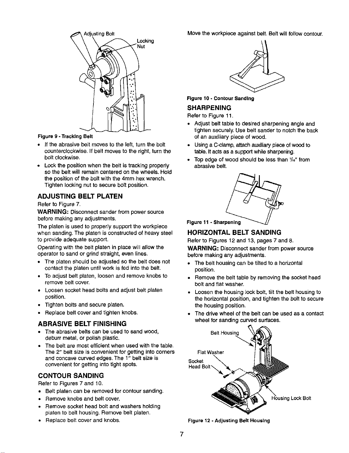
TRACKING ABRASIVE BELT
Refer to Figure 9, page 7.
• Test the tracking.Plug in power cord. Turn switch ON
and immediately OFF. Ifthe abrasive belt is centered
on wheels and did not move to the right or left, it is
tracking properly. If the belt moved to the right or left,
adjustment is necessary.
• To adjust the tracking wheel, loosen the locking nut
on adjusting bolt. Use a 4mm hex wrench to turn
adjusting bolt.
6
sting Bolt
Locking
Figure9 - TrackingBelt
• If the abrasive belt moves to the left, turn the bolt
counterclockwise. If belt moves to the right, turn the
bolt clockwise.
• Lock the position when the belt is tracking properly
so the belt will remain centered on the wheels. Hold
the position of the bolt with the 4ram hex wrench.
Tighten locking nut to secure bolt position.
ADJUSTING BELT PLATEN
Refer to Figure 7.
WARNING: Disconnect sander from power source
before making any adjustments,
The platen is used to properly support the workpiece
when sanding. The platen is constructed of heavy steel
to provide adequate support.
Operating with the belt platen in place will allow the
operator to sand or grind straight, even lines.
• The platen should be adjusted so the belt does not
contact the platen until work is fed into the belt.
• To adjust belt platen, loosen and remove knobs to
remove belt cover.
• Loosen socket head bolts and adjust belt platen
position.
• Tighten bolts and secure platen.
• Replace belt cover and tighten knobs.
ABRASIVE BELT FINISHING
• The abrasive belts can be used to sand wood,
deburr metal, or polish plastic.
• The belt are most efficient when used with the table.
The 2" belt size is convenient for getting into corners
and concave curved edges. The 1" belt size is
convenient for getting into tight spots.
CONTOUR SANDING
Refer to Figures 7 and 10.
• Belt platen can be removedfor contour sending,
• Remove knobs and belt cover.
• Remove socket head bolt and washers holding
platen to belt housing. Remove belt platen.
• Replace belt cover and knobs.
Move the workpiece against belt. Belt willfollow contour.
Figure10 - ContourSanding
SHARPENING
Refer to Figure 11,
• Adjust belt table to desired sharpening angle and
tighten securely. Use belt sander to notch the back
of an auxiliary piece of wood.
• Using a C-clamp, attach auxiliary piece of wood to
table. It acts as a support while sharpening.
• Top edge of wood should be less than '/,e"from
abrasive belt.
Figure11 - Sharpening
HORIZONTAL BELT SANDING
Refer to Figures 12 and 13, pages 7 and 8.
WARNING: Disconnect sander from power source
before making any adjustments.
• The belt housing can be tilted to a horizontal
position.
• Remove the belt table by removing the socket head
bolt and flat washer.
• Loosen the housing lock bolt, tilt the belt housing to
the horizontal position, and tighten the bolt to secure
the housing position.
• The drive wheel of the belt can be used as a contact
wheel for sanding curved surfaces.
Belt Housir
Flat Washer
Socket
Head Bolt "_
Lock Bolt
Figure 12 - Adjusting Belt Housing
7
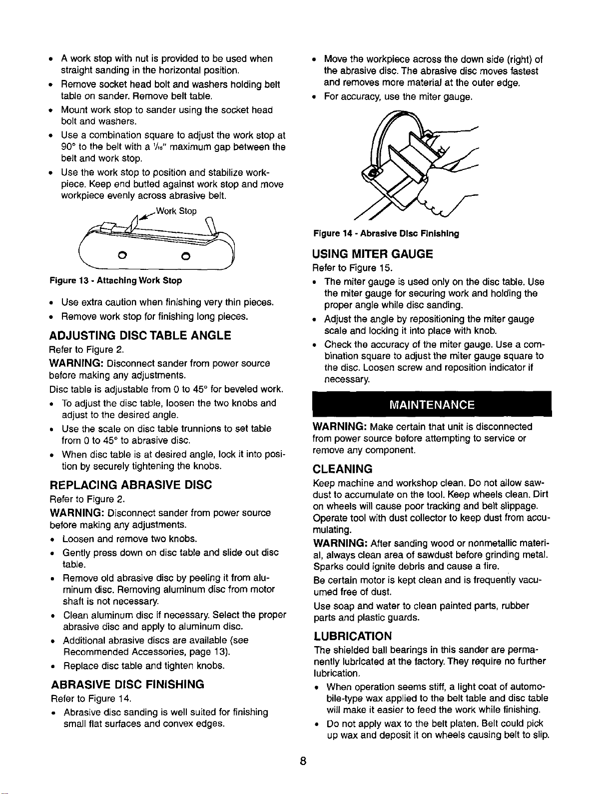
• A work stop with nut is provided to be used when
straight sanding in the horizontal position.
• Remove socket head bolt and washers holding belt
table on sander. Remove belt table.
• Mount work stop to sander using the socket head
bolt and washers.
• Use a combination square to adjust the work stop at
90° to the belt with a '/,8" maximum gap between the
belt and work stop.
• Use the work stop to position and stabilize work-
piece. Keep end butted against work stop and move
workpiece evenly across abrasive belt.
Figure 13 - Attaching Work Stop
• Use extra caution when finishing very thin pieces.
• Remove work stop for finishing long pieces.
ADJUSTING DISC TABLE ANGLE
Refer to Figure 2.
WARNING: Disconnect sander from power source
before making any adjustments.
Disc table isadjustable from 0 to 45° for beveled work.
• To adjust the disc table, loosen the two knobs and
adjust to the desired angle.
• Use the scale on disc table trunnions to set table
from 0 to 45° to abrasive disc.
• When disc table is at desired angle, lock it into posi-
tion by securely tightening the knobs.
REPLACING ABRASIVE DISC
Refer to Figure 2.
WARNING; Disconnect sander from power source
before making any adjustments.
• Loosen and remove two knobs.
• Gently press down on disc table and slide out disc
table.
• Remove old abrasive disc by peeling it from alu-
minum disc. Removing aluminum disc from motor
shaft is not necessary.
• Clean aluminum disc if necessary. Select the proper
abrasive disc and apply to aluminum disc.
• Additional abrasive discs are available (see
Recommended Accessories, page 13).
• Replace disc table and tighten knobs.
ABRASIVE DISC FINISHING
Refer to Figure 14.
• Abrasive disc sanding is well suited for finishing
small flat surfaces and convex edges.
• Move the workpiece across the down side (right) of
the abrasive disc. The abrasive disc moves fastest
and removes more material at the outer edge.
• For accuracy, use the miter gauge.
Figure 14 - Abrasive Disc Finishing
USING MITER GAUGE
Refer to Figure 15.
• The miter gauge is used only on the disc table. Use
the miter gauge for securing work and holding the
proper angle while disc sanding.
• Adjust the angle by repositioning the miter gauge
scale and locking it into place with knob.
• Check the accuracy of the miter gauge. Use a com-
bination square to adjust the miter gauge square to
the disc. Loosen screw and reposition indicator if
necessary.
WARNING: Make certain that unit is disconnected
from power source before attempting to service or
remove any component.
CLEANING
Keep machine and workshop clean. Do not allow saw-
dust to accumulate on the tool. Keep wheels clean. Dirt
on wheels will cause poor tracking and belt slippage.
Operate tool with dust collector to keep dust from accu-
mulating.
WARNING: After sanding wood or nonmetallic materi-
al, always clean area of sawdust before grinding metal.
Sparks could ignite debris and cause a fire.
Be certain motor is kept clean and is frequently vacu-
umed free of dust.
Use soap and water to clean painted parts, rubber
parts and plastic guards.
LUBRICATION
The shieldedball bearings in this sander are perma-
nently lubricated at the factory. They require no further
lubrication,
• When operation seems stiff, a light coat of automo-
bile-type wax applied to the belt table and disc table
will make it easier to feed the work while finishing.
• Do not apply wax to the belt platen. Belt could pick
up wax and deposit it on wheels causing belt to slip.
8

KEEP TOOL IN REPAIR
• If power cord isworn, cut, or damaged in any way,
have it replaced immediately.
• Replace worn abrasives when needed.
• Replace any damaged or missing parts. Use parts
list to order parts.
Any attempt to repair motor may create a hazard unless
repair is done by a qualified service technician. Repair
service is available at your nearest Sears store.
9
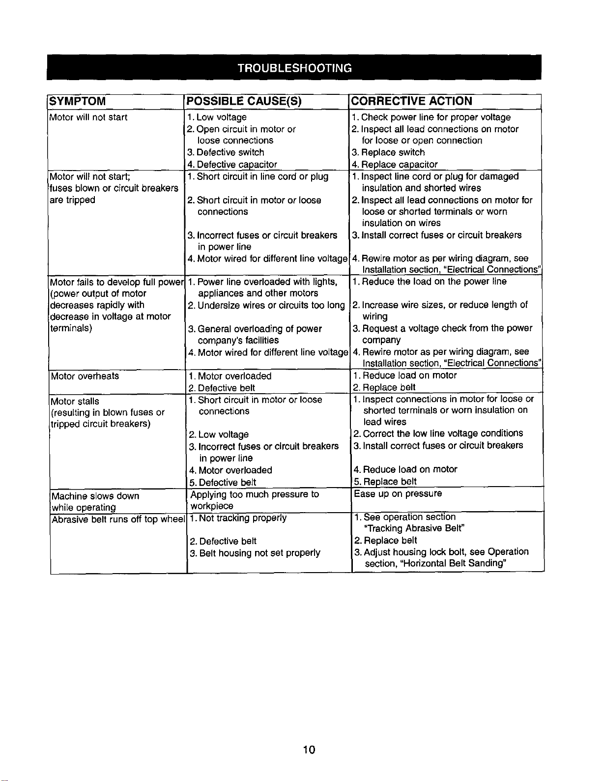
SYMPTOM
Motor will not start
Vlotor will not start;
!fuses blown or cimuit breakers
are tripped
Motor fails to develop full power
(power output of motor
decreases rapidly with
decrease in voltage at motor
terminals)
Motor overheats
Motor stalls
(resulting in blown fuses or
tripped circuit breakers)
Machine slows down
while operating
Abrasive belt runs off top whee,
POSSIBLE CAUSE(S)
1.Low voltage
2. Open circuitin motoror
loose connections
3. Defective switch
4. Defective capacitor
1.Short circuitin linecord or plug
2. Short circuit in motor or loose
connections
3. Incorrectfuses or circuit breakers
in power line
4. Motor wired for different line voltage
1. Power line overloaded with lights,
appliances and other motors
2. Undersize wires or circuits too long
3. General overloading of power
company's facilities
4. Motor wired for different line voltage
1.Motor overloaded
2. Defective belt
1.Short circuit in motor or loose
connections
2. Low voltage
3. Incorrectfuses or circuit breakers
in power line
4. Motor overloaded
5. Defective belt
Applying too much pressure to
workpiece
1. Not tracking properly
2. Defective belt
3. Belt housing not set properly
CORRECTIVE ACTION
1.Check power line for proper voltage
2. Inspect all lead connections on motor
for loose or open connection
3. Replace switch
4. Replace capacitor
1. Inspect line cord or plug for damaged
insulation and shorted wires
2. Inspect all lead connections on motor for
loose or shorted terminals or worn
insulation on wires
3. Install correct fuses or circuit breakers
4. Rewire motor as per wiringdiagram, see
Installation section, "Electrical Connections"
1.Reduce the load on the power line
2. Increase wire sizes, or reduce length of
wiring
3. Request a voltage check from the power
company
4. Rewire motor as per wiring diagram, see
Installation section, "Electrical Connections"
1.Reduce load on motor
2. Replace belt
1.Inspect connections in motor for loose or
shorted terminals or worn insulation on
lead wires
2.Correct the low line voltage conditions
3.Install correct fuses or circuit breakers
4. Reduce load on motor
5. Replace belt
Ease up on pressure
1.See operation section
"Tracking Abrasive Belt"
2. Replace belt
3. Adjust housing lock bolt, see Operation
section, "Horizontal Belt Sanding"
10

NOTES
11
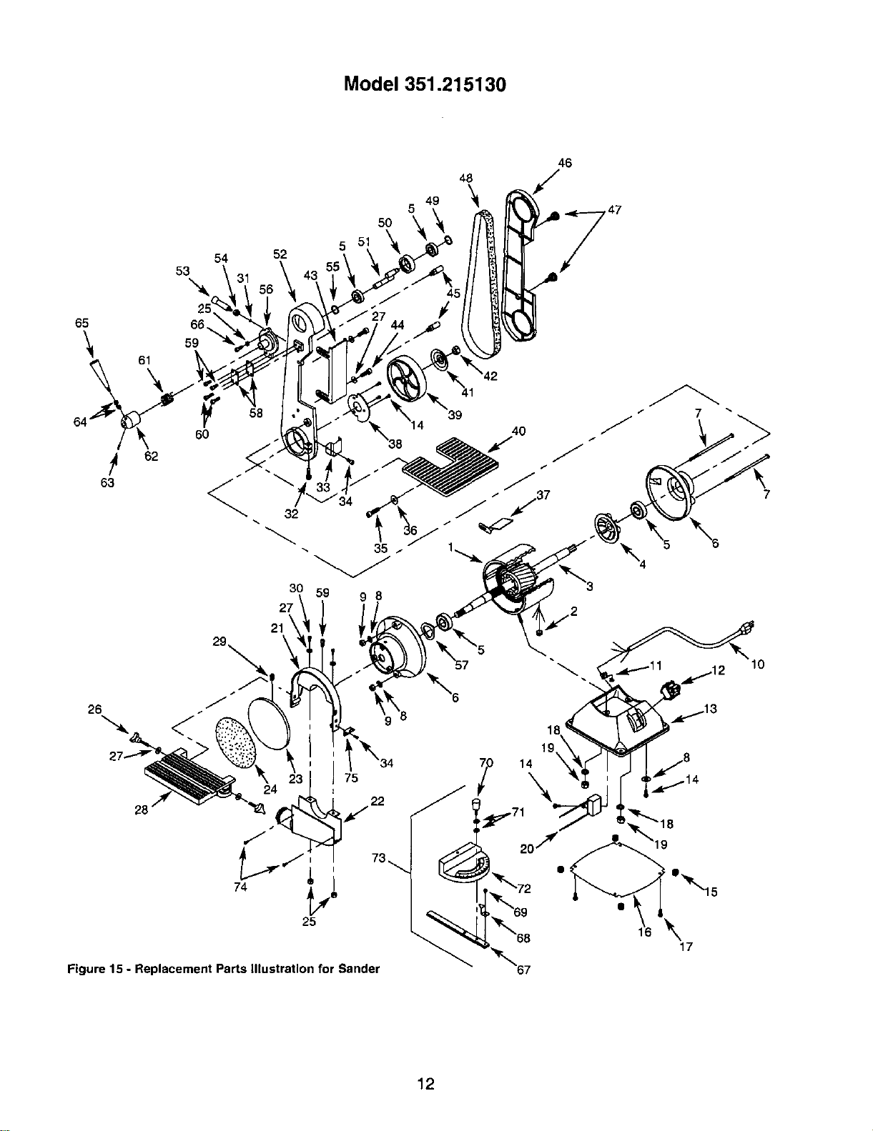
Model 351.215130
52
5O
5
48
49 '_
5
46
65 66._
"_ 61 59
64 60
62
63
58
7
21
75
Figure 15 - Replacement Parts Illustration for Sander
'_72
_r"_69
_t'_68
"_"67
\
17
12

KEY KEY
NO. PART NO. QT_ NO,
1
2
3
4
5
6
7
8
9
10
11
12
13
14
15
16
17
18
19
20
121
22
23
-_4
_-5
_-6
27
28
29
30
31
32
33
34
35
36
37
38
39
40
21457.00
01066.00
21480.00
01608.00
STD315225
21479.00
08425.00
STD551210
STD840508
00067.00
04055.00
08066.00
16906.01
03207.00
04051.00
16909.00
03210,00
STD551125
STD541025
16908.00
21482.00
04656.00
04657.00
9-28313
STD840610
04658.00
STD851006
21433.00
STD502502
STD870620
STD851008
STD870830
04659.00
STD870408
01002.00
STD851010
04660.00
03317.00
04661.00
04662.00
DESCRIPTION
Stator with Housing
Grommet
Armature
Motor Fan
Bearing 6202Z.Z*
Endshield
Thru Bolt
#10 Serrated Washer*
5-O.8mm Hex Nut*
Line Cord
Strain Relief
Rocker Switch with Key
Base
#10-24 x 3/8" Flange Screw
Base Bumper
Base Cover
#10-24 x 1/4" Flange Screw
1/4" Lock Washer*
1/4"-20 Hex Nut*
Capacitor 16MFD
Disc Guard
Dust Collection Chute
Aluminum Disc
l-Abrasive Disc
6-1.0mm Hex Nut*
Knob
6mm Flat Washer*
Disc Table
1/4-20 x 1/4" Set Screw*
6-1.0 x 20mm Socket Head Bolt*
8mm Flat Washer*
8-1.25 x 30mm Socket Head Bolt*
Lower Belt Guard
4-0.7 x 8mm Socket Head Bolt*
10-1.5 x 25mm Socket Head Bolt
1Omm Flat Washer*
Work Stop
Stop Bracket
Drive Wheel
Belt Table
1
1
1
1
4
2
2
3
2
1
1
1
1
5
Standard hardware item available locally.
Not Shown
1 Available in larger Sears stores and catalog.
4
1
4
2
2
1
1
1
1
1
3
2
6
1
1
2
1
1
1
2
1
1
1
1
1
1
41
42
43
44
45
46
47
48
49
5O
51
52
88
56
57
68
59
60
61
82
63
64
65
66
67
68
69
70
71
72
73
74
75
t_
b,
PART NO. DESCRIPTION
00065.01
00548.00
16632.00
STD870610
04664.00
16633.00
08273.00
9-28481
00533.00
04666.00
04667.00
16634.00
04669.00
STD840812
00341.00
04670.00
08283.00
03327.01
STD870510
STD870520
04671.00
04672.00
00351.00
STD541031
!04673.00
STD870625
04272.01
00901.00
16684.00
07557.00
STD651006
00904.00
07800.01
STD863512
21481.00
01345.00
21489.00
20067.01
Wheel Flange
1/2"-12 Hex Nut
Belt Platen
6-1.0 x 12mm Socket Head Bolt*
Stand Off
Belt Cover
Knob
1"AbrasiveBelt
3AM1o15 Retaining Ring
Tracking Wheel
Tracking Wheel Cam
Belt Housing
Horizontal Stop
8-1.25mm Hex Nut*
3AMI-17 Retaining Ring
Tracking Bracket
25mm Wavy Washer
Spring Plate
5-0.8 x 10mm Socket Head Bolt*
5-0.8 x 20mm Socket Head Bolt*
Tension Spring
Spring Cap
6-1.0 x lOmm Set Screw
5/16"-18 Hex Nut*
Handle Assembly
6-1.0 x 25mm Socket Head Bolt*
Miter Gauge Slide Bar
Indicator
#8-24 x 1/4" Washer Head Screw
Knob
6mm Flat Washer*
Protractor Scale
Miter Gauge Assembly
(Includes Key. Nos. 67-72)
5-0.8 x 12mm Pan Head Screw*
Pointer
1 x 42" Abrasive Belt
Parts Bag
Operator's Manual
QTY,
1
1
1
2
2
1
2
1
1
1
1
1
1
1
1
1
1
2
3
2
1
1
1
2
1
1
1
1
1
1
2
1
1
2
1
1
1
1
Recommended Accessories
Abrasive Belts 2 x 42" (Fine) 9-28480
Abrasive Belts 2 x 42" (Medium) 9-28481
t_ Abrasive Belts 2 x 42" (Coarse) 9-28482
Abrasive Disc 6" (Assorted) 9-28973
Abrasive Belts 1 x 42" (Fine) 9-28409
Abrasive Belts 1 x 42" (Medium) 9-28410
t, Abrasive Belts 1 x 42" (Course) 9-28411
t_ Abrasive Cleaner 9-28000
13
LIJADORA
Correa de 5,1 x 107 cm
Disco de 15,2 cm
Modelo No.
351.215130
PRECAUClON: Lea este manual y siga las
Reglas de Seguridad y las Instrucciones de
Operaci6n, antes de usar este producto pot
primera vez.
Ingles .............................................. 2-10
Ilustracidn y lista de partes ............................. 12-13
Garantfa .............................................. 14
Reglas de seguridad.................................. 14-15
Desempaque .......................................... 15
Montaje ............................................ 15-16
Instalaci6n .......................................... 16-17
Operacidn .......................................... 17-20
Mantenimiento ...................................... 20-21
Identificacidn de pmblemas ............................... 22
Use zapatosde seguridadcon suelasantideslizantes.
Use galas de seguridad, que cumplan con ANSI Z87.1 de
Estados Unidos. Los anteojos corrientes tienen solamente
lentes resistentes al impacto. NO sonanteojos de seguridad.
Use una m&scara para la cara o una m_scara para el polvo,
si la operacidn de lijado produce polvo.
Est_ alerta y piense claramente.Nunca opere herramientas
mec&nicas cuandoest_ cansado,intoxicadoo cuando est_
tomandomedicamentosque causan somnolencia.
PREPARACION DEL AREA PARA EJECUTAR EL
TRABAJO
Mantengael&realimpia.Lasdreasdetrabajodesordenadas
atraenaccidentes
No use herramientas mec&nicas en ambientes peligrosos. NO
use herramientas mec_nicas en lugares hOmedos o mojados.
No exponga las herramientas mec,_nicas a la Iluvia.
El &rea de trabajo debe estar iluminada adecuadamente.
Tiene que haber disponible un receptaculo el_ctrico adecuado
para la herramienta. El enchufe de tres puntas se tiene que
enchufar directamente en un reeept_culo de tres puntas
conectado a tierra correctamente.
Loscordones de extensi6n deben tener una punta de co-
nexidn a tierra y los tres alambres del corddn de extensibn
deben ser del calibre correcto.
Mantenga a los visitantes a una distancia prudente del drea
de trabajo.
Mantenga a los nifios fuera del lugar de trabajo. Haga que
su taller sea a prueba de nifios.Use candados,interruptores
principales o remueva las Ilaves del interruptor para evitar el
uso no intencional de las herramientas mec&nicas.
GARANTIA COMPLETA DE UN AI_IO
Si fallara este productoporcausade defectosen el materialen la
mano de obraen unlapsode unar_oa partirde lafechade
compra,Sears Ioreparar&o reemplazar&,a su eleccidn,sincosto
adicional.Soliciteal Centrode servicioSears (1-800-4-MY-HOME)
m_s cereanolareparaci6n del producto odevu_lvaloal establec-
imiento donde Io adquiri6
Sieste producedse usa parafinescomercialeso de alquiler,esta
garantia es v_lidapor90 dfas a partirde la fechade compra.
EstagarantfaaplicaL_nicamentecuandoelproductose utilizaen
losEstadosUnidos.
Estagarantfaleotorgaderechoslegalesespecfficosy tambi_n
puedeustedtarter otrosderechosque varfende estadoa estado.
Sears, Roebuck and Co., Dept. 817WA, Hoffman Estates,
IL 60179
ADVERTENCIA: Parssu propiaseguridad, lea todas las
instruccionesy lasprecaucionesantesde operar laherramienta.
PRECAUClON: Siempresiga losprocedimientosde operacidn
correctos,tal cored se definenen este manual,aun cuandoest_
familiarizadocon el usede _sta o de otrasherramientas similares.
Recuerde que si no se tienecuidado por aunque sea una fmccidn
de un segundo, se pueden producir lesionespersonalesgraves.
ESTE PREPARADO PARA EL TRABAJO
Use ropa apropiada. No use ropa suelta,guantes,corbatas,
anillos, pulseras uotras joyas que puedan quedar atrapadas
en las partes mdviles de la m_lquina.
Use una cubierta protectora para el eabello,para sujetar el
cabello largo.
ES IMPORTANTE MANTENER LAS HERRAMIENTAS
Desenchufesiemprela herramienta antesde inspeccionarla.
Consulte el manual para informarse sobre los procedimientos
de mantenimiento y ajuste especfficos.
Mantenga la herramienta lubricaday limpia, para obtaner una
operacidn m_s segura.
Remueva las herramientas de ajuste.Fdrmese el h&bitode
revisar para verificar si las herramientas de ajuste se han
removido antes de encender ia mdquina.
Mantenga todas las partes listas para funcJonar.Revise para
determinar que el protector uotras partes operar_n correcta-
mente y har_n el trabajo para el que fueron dise_adas.
Revise para verificar si hay partes datladas. Revise para
verificar el alineamientode las partes movibles, si hay atas-
camiento, rotaras y montaje oeualquier otra condicidn que
pudiera afectar la operacidn de la herramienta.
• Si hay una protecciOn o cualquier otra parte datlada, tiene
que repararse correctamente o cambiarse. No haga repara-
ciones provisorias. (Use la listade partes que viene incluida
para ordenar las partes de repuesto.)
EL OPERADOR DEBE SABER COMO USAR LA
HERRAMIENTA
• Use laherramientacorrectaparael trabajo,Nofuercela
herramienta, o el accesorio,ni losuse para untrabajo para
el cual no ban sido dise_ados.
• Desconecte la herramienta cuando cambielacorrea o el
disco abrasivo.
Evite el arranque pot accidente. AsegLirese que el interruptor
de la herramienta estd en la posicidn "apagado" (off) antes de
enchufarla
14
• NOfuerce la herramienta.Trabajard en la forma rods eficiente
ala velocidadpare la cualfue disedada.
• Mantenga las manes alejadas de las partesm6viles yde las
superficiesJijadoras.
• Nunca deje que una herramienta funcione sola. Descon_ctela
yno se vaya hasta que se detenga completamente.
No trate de alcanzar demasiado lejos,Mant_ngasefirme
yequilibrado.
• Nunca se pare en la herramienta.Se pueden producir
lesionesgravessi la herramientaso inclina, o sise toca
eldisco o la correaperaccidente.
• Conozcasu herramienta.Aprenda la eperacidnde laherra-
mienta, aplicacibny limitacionesespecificas.
• Use los accesoriosque se recornienda.(Refidrasea la p_gina
13.) Si se usan accesoriosincorrectos,se puede producir
riesgo de lesionespersonales.
Deje las manes libres pareoperar la mdquina. Protdjalasde
posibleslesiones.
• Desconectela mdquina si se atasca. Lacortadorase atasca
cuandopenetrademasiado profundamenteen la piezade
trabajo.(La fuerza del motorlarnantienepegadaa lapieza
de trabajo.)
• Soportela pieza de trabajocon laguia de ingletes,la platina
de laeorrea, eltope del trabajoo la mesa de trabajo,
• Mantenga un espacio libre mdximo de 1,6mm entre lamesa
y]a correa,o el discopara lijar.
PRECAUCION: iPiense en la seguridad!La seguridades una
combinacibnde sentido comendel operadoryde esteralerta
en todo rnomentocuandose est_ usandolaherramienta.
ADVERTENCIA: No trate de operarla herramienta haste que
est_ completamentemontada seg,',nlas instrucciones.
Refi_rase a la Figura 1.
Revise si han ocurrido da_os durante el transporte. Si hart ocurri-
do dahos, se tiene que presentar un reclamo ala compaSfa de
transportes para que se tomen medidas rdpidamente.
Es necesario encontrar y contar las partes que deben ajustarse a
la unidad:
A Conjunto de la mesa
B Disco abrasivo
C Conjunto de la gufade ingletes
D Coreadel"
E Mesa de lacorrea
La bolsa de partes (No. de Parle 21489.00) incluyes: barra de
tope horizontal, indicadore, tope funcional, dos manillas, un
perno de cabeza hueca, 10-1,50 x 25 mm, una perno de cabeza
hueca de 4-0,7 x 8 mm, una arandela plana de 10 ram, dos
arandelas planas de 6 mm, una tuerca hexagonal de 8-1,25 ram,
Ilaves hexagonales de 3, 5, 6 y 8 mm (una de cada una) y una
Ilavehexagonal extra larga de 3 ram.
A C
Flgura 1 - Desempaque
Refi_rase a las Figuras 2 y 3.
PRECAUCION: No trate de montarla sihay partes que faltan.
Useel manual del operadorpara ordenarlas partesde repuesto.
INSTALACION DEL DISCO ABRASIVe EN EL DISCO
DE ALUMINIO
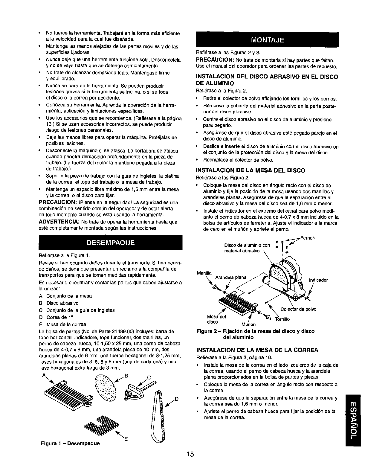
Refi_rasea la Figura2.
Retireel colector de polvoaflojando lostornillosy lospernos.
Remuevala cubiertadel material adhesiveen la parteposte-
riordel disco abrasive.
Centre eldiscoabrasiveon el discode aluminioy presione
parapegarlo,
AsegLiresede que el discoabrasiveest_ pegadoparejoen el
discode aluminio,
Deslicee inserteel discode aluminiocon eldiscoabrasiveen
elconiuntode la protecciOndeldiscoy lamesa deldisco,
Reemplace el colectorde polvo,
INSTALACION DE LA MESA DEL DISCO
Refi6rase a las Figura2.
Coloquela mesadel disco en dngulo recto conel discode
aluminioy fije laposicibnde ta mesausandodos manillas y
arandelasplanas. Asegerese de que laseparacibnentre el
discoabrasivey la mesa del disco sea de 1,6 mm o menor.
Instale el indicadoren el extreme delcanal para polvomedi-
anteel perno de cabeza huecade 4-0,7 x 8 mm incluido en la
bolsade artfculosde ferreterla. Ajuste el indicador ala mama
de cero en el mutidn y aprieteel perno.
Disco de a]uminio con _Pernos
materialabrasivo \ ;
\ Arandelaplana j'_ "'_'_ Indcador
Manilla i_ '
,om,,,o
Figure 2 - Fljacl6n de la mesa del disco y disco
del aluminlo
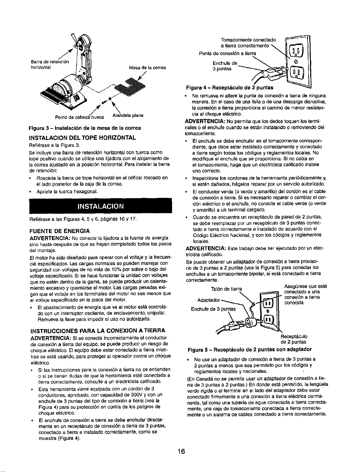
INSTALACION DE LA MESA DE LA CORREA
Refi_rase ala Figure3, pdgina16.
• Instalela mesa de la correaen el lade izquierdo de [a eaja de
la correa,usandoel perno de cabeza hueca y laarandela
planeproporcionadosen Is boisede partesy piezas.
• Coloquela mesa de la correaen &ngulo rectocon respecto a
la correa.
• AsegtJresede que la separacibnentre lamesa de la correay
lacorrea sea de 1,6 mm o menor.
• Apriete el pernode cabeza hueca pare fijar la posicibnde la
mesade lacorrea.
15
Barrade retenci6n
horizontal Mesade la correa
Pemodecabezah/h_ueca" A_randelaplana
Flgura 3 - Instalacl6n de la mesa de la correa
INSTALACION DEL TOPE HORIZONTAL
Refi_rasea la Figura3.
Se incluyeuna barra de retenci6nhorizontalcontuercacomo
tope positivocuando se utilicauna lijadora conel alojamiento de
laoorreaajustadoenla posici6nhorizontal.Para instalarla barra
de retancibn:
Roscada la barra de tope horizontal en el orificioroscadoen
el lado posteriorde lacaja de lacorrea.
Apriete la tuercahexagonal.
Refi_,rasea las Figuras4, 5 y 6, pdginas 16 y 17.
FUENTE DE ENERGIA
ADVERTENCIA: No conectela lijadoraa la fuente de energfa
sino hasta despu_s de que se hayan completadotodoslos pasos
del monta[e.
El motor ha sido disefiado para operar con el voltaje y la frecuen-
cia espeoificados. Las cargas normales se pueden rnanejar con
segufidad con voltajes de no rods de 10% pot sobre o bajo del
voltaje especificado. Si se hace funcionar la unidadcon voltajes
que no est_,ndentro de la gama, se puede producir un calenta-
miento excesivo y quemarse el motor, Las cargas pesadas exi-
gen que el voltaje en los terminales del motor no sea menos que
el voltaje especificado en la placa del motor.
El abastecimiento de energfaque va al motorestd controla-
do con un interruptor oscilante, de enclavamiento, unipolar.
Remueva la Ilave para impedir el uso no autorizado.
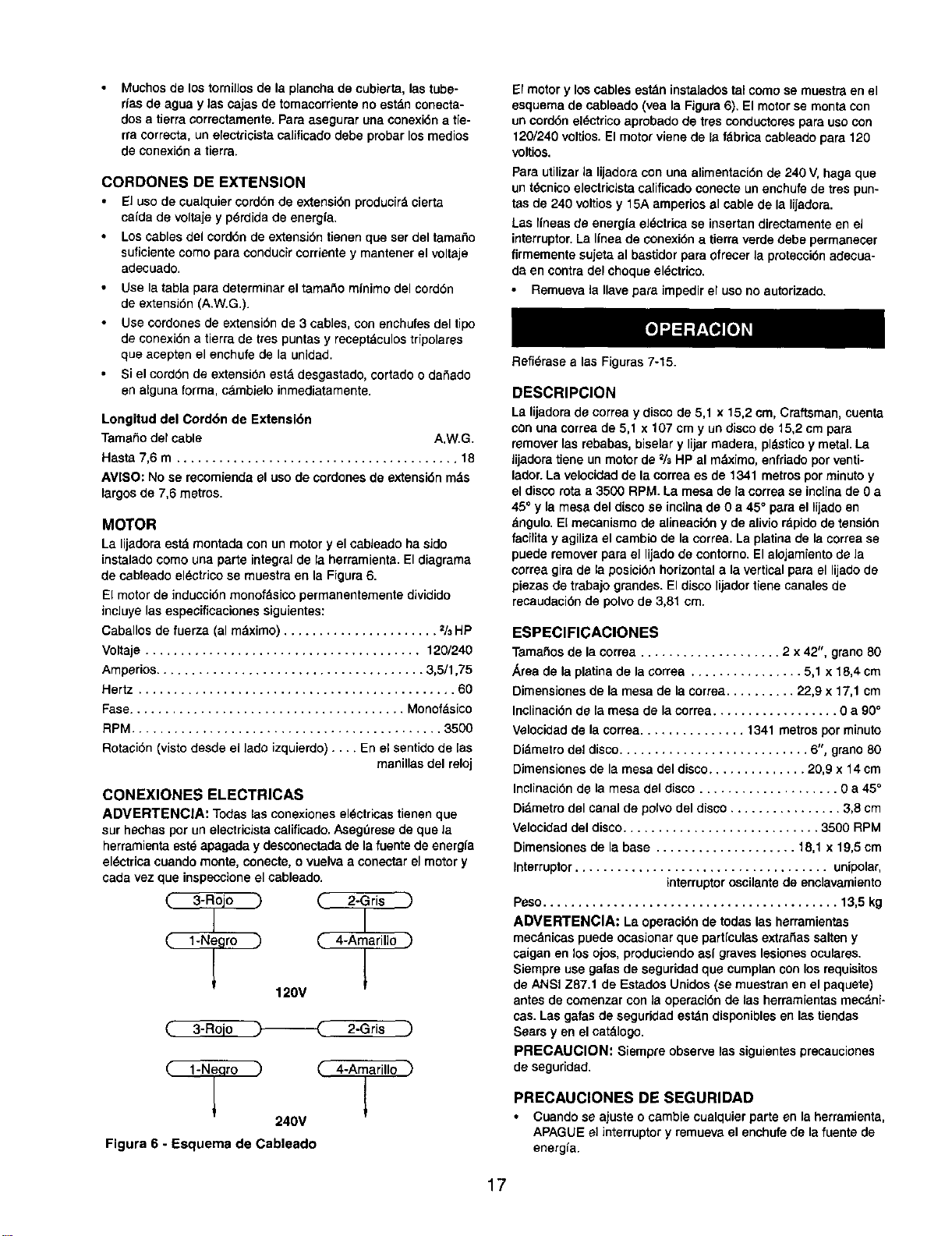
INSTRUCCIONES PARA LA CONEXION A TIERRA
ADVERTENCIA: Si se conectaincorrectamente el conductor
de conexi6na tierradel equipo,se puedeproducirunriesgode
choqueel_ctrico. Elequipodebe estar conectadoa tierramien°
tras se est_ usando,para protegeral operadorcontraunchoque
el_ctrico.
Si las instruccionespara la conexi6na tierrano se entienden
o si se tienen dudas de que la herramienta est_ conectada a
tierra correctamente, consultaa un electricista caUficado.
Esta herramienta vieneequipada con un cord6n de 3
conductores, aprobado, con capacidad de 300V y con un
enchufe de 3puntas del tipo de conexi6n a tierra (vea la
Figura 4) para su protecci6n en contra de los peligros de
choqueel_ctrico.
• El enchufe de conexi6n a tierra se debe enchufar directa-
mente en un recept_culo de conexi6n a tierra de 3 puntas,
conectado a tierra e instalado correctamente, como se
muestra (Figura 4).
Tomacorrienteconectado
a tierra correctamente
\
Punta de conexi6na tierra
Enchufede _
3 pantas
Figura 4 - Receptdculo de 3 puntas
• No remuevani alterela puntade conexi6na tierrade ninguna
manera.En el caso deuna falla o de una descargadisruptive,
laconexi6na tierra proporcionael caminode menor resisten-
ciaal choque eldctrico.
ADVERTENCIA: No permitaque losdedostoquenlostermi-
naleso el enchufe cuando se estdn instalandoo removiendodel
tomaoorriente,
• El enchufe se debe enohufar en el tomacorriente correspon-
diente, que debe estar instalado correctamente y coneotado
a tierra seg0n todos los c6digos y reglamentos locales. No
modifique el enchufe que se proporciona. Si no calza en
el tomacorriente, haga queun electricista calificado instale
uno correcto.
• Inspaccioneloscordones de la herramienta peri6dicamenta y,
si est_,ndafiados,h_galos reparar por unservicioautorizado.
Elconductorverde (o verde y amarillo)del cord6nes elcable
de conexi6na tierra.Si es necesarioreparar o cambiarel cor-
d6n eldctricoo el enchufe,noconeoteel cable verde (o verde
yamarillo)a un terminalcargado.
Cuandose encuentra un recaptdculode pared de 2 puntas,
se debe reemplazarpor unreoeptdculode 3 puntasconec-
tado a tierracorrectamentee instalado de acuerdocon el
C6digo El_ctrico Nacional,y con los cddigosy reglamentos
locales.
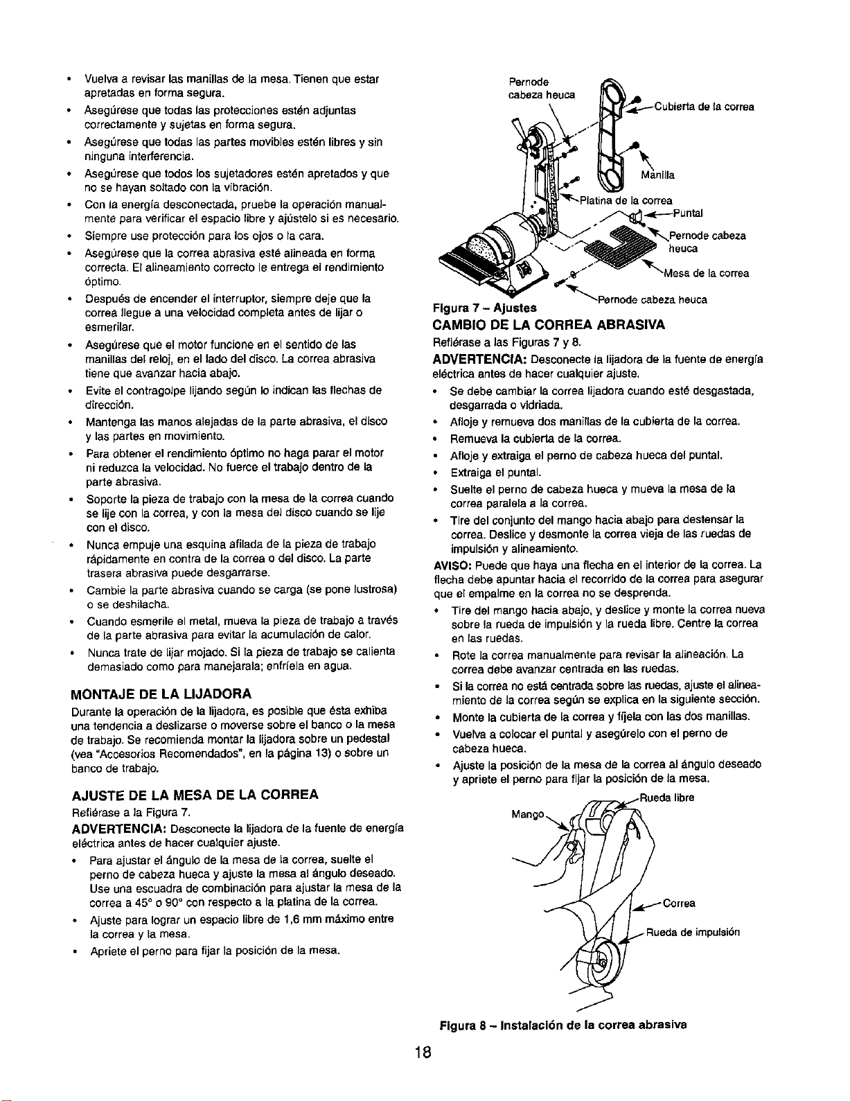
ADVERTENClA: Estatrabajodebe ser ejecutadopot unelec-
tricistacalificado.
Se puede obtenerun adaptadorde conexi6na tierraproviso-
rio de 3 puntas a 2 puntas(vea la Figura5) para conectarlos
enchufes a untomacorrientebipolar,siest_ conectadoa tierra
correctamente.
Tal6n detierra Aseg_Jreseque estd
.,..._ ,X_._I." conectadoa una
conexibn atierra
Adaptador conocida
cuo o .
Recaptdculo
de 2 puntas
Figura 5 - Receptdculo de 2 puntaa con adaptador
• No use unadaptador de conexi6n a tierrade 3 puntas a
2 puntas a menos que sea permitido por losc6digos y
reglamentos locales y nacionales.
(En Canadd no se permite usar un adaptador de oonexi6n a tie-
rra de 3 puntasa 2 puntas.) En donde estd permitido, [aleng{3eta
verde rfgida o el terminal en el tadodel adaptador debe estar
conectado firmemente a una conexi6n a tierra elL=ctricaperma-
nente, tal como una tuberfa de agua conectada a tierra correcta-
mente, una caja de tomacorriente conectadaatierra eorrecta-
mentao un sistema de cables conectado a tierracorrectamente.
16
Muchos de los tornillos de la plancha de cubierta, las tuba-
rfas de agua y ]as cajas de tomaeorriente no est_n conecta-
dos a tierra correctamente. Para aaegurar una conexidn a tie-
rra correcta, un electricista calificado debe probar los medios
de conexidn a tierra.
CORDONES DE EXTENSION
El usode cualquiercord6nde extensidnproducirt=cierta
cafda devoltaje y p_.rdidade energfa.
Loscablesdelcorddnde extensidntienenque ser deltamafio
suficientecomo para conducircorrieotey mantenerelvoltaje
adecuado.
Use la tabla para determinar el tamafio minimo del cordbn
de extensidn (A.W.G.).
Use cordones de extensidn de 3 cables, con enchufes del tipo
de eonexidn a tierra de tres puntas y receptdculos tripolarss
que acepten el enchufe de la unidad.
Si el corddn de extensidn est& desgastado, cortado o dafiado
en alguna forma, c&mbielo inmediatamente.
Longitud del Corddn de Extensidn
Tamafio del cable A.W.G.
Hasta 7,6 m ........................................ 18
AVISO: No se recomienda el uso de cordones de extensidn m_s
largos de 7,6 metros.
MOTOR
La lijadoraest_ montada con un motory elcableadoha sido
instalado como una parte integralde laherramienta.Eldiagrama
de cableado el_ctrico se muestra en la Figura 6.
El motor de induccidn monof_sico permanentemente dividido
incluye las especificaciones siguientes:
Caballos de fuerza (al m&ximo) ...................... 2/3HP
Voltaje ....................................... 120/240
Amperios...................................... 3,5/1,75
Hertz ............................................. 60
Fase....................................... Monofdsico
RPM............................................ 3500
Rotacidn (visto desde el lade izquierdo) .... En el sentido de [as
manillas del reloj
CONEXlONES ELECTRICAS
ADVERTENClA: Todaslasconexiones el_ctricas tienenque
sur he(has per un electricista calificado. Aseg_rese de que la
herramienta este apagada y desconectada de la fuente de energla
sl_ctrica cuando monte, eonecte, o vuelva a cone(tar el motor y
cada vez que inspeccione el cableado.
"_ C 2-Grisl
C 4"Aiarill° _)
120V
2-Gris )
C 4-Aiarillo "_
240V
Figura 6 - Esquema de Cableado
El motor y los cables est&n instalados tal coma se muestra en el
esquema de cableado (yea la Figura 8). El motor se monta con
un corddn el_etrico aprobado de tres conductores para uso con
120/240 voltlos. El motor viene de la fdbrica cableado para 120
voltios.
Para utilizarla lijadora con una alimentaci6nde 240 V, haga que
untdcnicoele(tricist_ca[ificadoeonecteunenchufede trespun-
tas de 240 voltiosy 15A arnperiosal cable de la lijadora.
Las Ifneas de energfael_.ctricase insertandirectamente en el
interruptor.La linea de conexidn a tierraverdedebe permane(er
firmemente sujeta al bastidorparaofre(er la prote(cidnade(ua-
da en contradel choqueel_.ctrico.
Remuevala Ilavepara impedir el usono autorizado.
RefiOrase alas Figuras 7-15.
DESCRIPCION
La lijadorade correay disco de 5,1 x 15,2em, Craftsman,cuenta
con una correade 5,1 x 107 cm y undiscode 15,2 cmpara
removerlas rebabas,biselary lijarmadera, pldstico y metal.La
lijadoratiene unmotorde % HP al m_,ximo,enfriadoporventi-
lador.La velocidadde la correa es de 1341 metrosper rninutoy
eldiscorota a 3500 RPM. La mesa de la correase inciinade 0a
45° yla mesadel discose incUnade 0 a 45° para el lijado en
dngulo. El mecanismo de alineacibny de alivior_pidode tensidn
facilita y agiliza elcambio dela correa.La platinade lacorrease
puederemoverpara el lijadodecontorno.El alojamientode la
correagira de la posici6nhorizontal a la vertical para el lijadode
piezasde trabajograndes. Eldisco lijadortienecanalesde
recaudacidnde polvode 3,81 era.
ESPEClFICACIONES
Tamafiosde lacorrea .................... 2 x42", grano80
,_reade la platinade la correa ................ 5,1 x 18,4 cm
Dimensionesde la mesade la correa.......... 22,9 x 17,1 cm
Inclinacidnde la mesa de la correa.................. 0 a 90°
Velocidadde la correa............... 1341 metros porminuto
Di_metrodel disco........................... 6", grano80
Dimensiones de la mesadeldisco.............. 20,9 x 14 cm
Inclinaci6nde la mesa del disco .................... 0 a 45°
Didmetrodel canalde polvodel disco................ 3,8 cm
Velocidaddel disco............................ 3500 RPM
Dimensionesde la base .................... 18,1 x 19,5 cm
Interruptor.................................... unipolar,
interrupter oscUantede enclavamiento
Peso.......................................... 13,5kg
ADVERTENCIA: La operacidnde todaslas herramientas
mec_nicaspuedeocasionarque partlculasextrafiassalteny
caigan en losojos,produciendoasi graveslesionesoculares.
Siempreuse gafasde seguridadque cumplanconlos requisitos
de ANSI Z87.1 de EstadosUnidos(semuestran en el paquete)
antes decomenzar conla operacidnde lasherramientasmecdni-
cas.Las galas de seguridadest_n disponiblesen lastiendas
Sears yen el cat&logo.
PRECAUClON: Siempre observelas siguientespre(auciones
de seguridad.
PRECAUClONES DE SEGURIDAD
• Cuandose ajusteo cambiecualquierparte en laherramienta,
APAGUEel interruptor y remuevael enchufede lafuentede
energia.
17
Vuelvaa revisar las manillas de la mesa.Tienen que estar
apretadas en forma segura.
AsegL_resequa todas las protecciones esten adjuntas
correctamente y sujetas en forma segura.
Aseg_rese que todas las partes movibles esten libres y sin
ninguna interferencia.
Aseg_rese que todos los sujetadores est_n apretados y que
no se hayan soltado con Is vibracidn.
Con le energfa desconectada, pruebe la operacidn manual-
mente para verificar el espacio libray ajOstelosi es necesario.
Siempre use protecci6n pare los ojos o la cara.
Aseg_rese que la eorrea abrasiva esta alineada en forma
correcta. El aJineamientocorrecto le entrega el rendimiento
optimo.
Despu_s de encender el interruptor, siempre deje qua la
corree Ileguea una velooidad completa antes de lijar o
esmerilar.
AsegOrese que el motor funcione en el sentido de las
manillas del reloj, en el lado del disco. La correa abrasiva
tiene que avanzar hacia abajo.
Evite el contragolpe lijando seg_n Ioindican las flechas de
direecibn.
Mantenga las manos alejadas de la parte abrasiva, el disco
y las partes en movimiento.
• Para obtener el rendimiento dptimo no hage parar el motor
ni reduzoa la velocidad. No fuerce el trabajo dentro de la
parte abrasive.
• Soporta la pieza de trabajo con la mesa de la correa cuando
se lije con lacoffee, y con le mesa del disco cuando se lije
con el disco.
• Nunca empuje una esquina afiladade la plaza de trabajo
rapidamente en contra de la correa o del disco. La parte
trasere abrasiva puede desgarrarse.
• Cambie la parte abrasiva cuando se carga (se pone lustrosa)
o se deshilacha.
• Cuando esmerile el metal, mueva la pieza de trabajo a tray,s
de la parte abrasiva para evitar la acumulacidn de calor.
Nunca trate de lijar mojado. Si Eapieza de trabajo se calienta
demasiado como para manejarala; enfrfela en agua.
MONTAJE DE LA LIJADORA
Durante la operacidnde la lijadora, es posible que _sta exhiba
una tendenciaa deslizarseo moverse sobre el bancoo lamesa
de trabajo.Se recomiendamontar la lijadora sobre unpedestal
(vea =Accesorios Recomendados",en la pdgina 13)o sobre un
bancode trabajo.
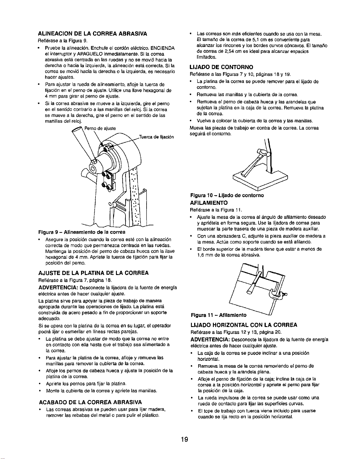
AJUSTE DE LA MESA DE LA CORREA
Refi_rasea ]a Figura 7.
ADVERTENClA: Desconecte la lijadora de la fuente de energfa
el_ctrica antesde hacer cuelquier ajuste.
Para ajustar el &ngulo de lamesa de la correa, suelte el
perno de cabeza hueca y ajuste la mesa el dngulodeseado.
Use una escuadra de combinacidn para ajustar la mesa de la
correa a 45° o 90° con respecto a la platina de la oorrea.
• Ajuste para Iogrer un espacio libre de 1,6 mm m&ximo entre
la correa y la mesa.
• Apriete el perno para fijar le posicidn de la mesa.
Pemode
cabeza heuca
-,K------Puntal
Pernode cabeza
heuca
abeza heuca
Flgura 7 - Ajuetes
CAMBIO DE LA CORREA ABRASIVA
Refi_msea ias Figuras7 y 8.
ADVERTENC|A: Desconecte la lijadorade la fuente de energfe
el_ctricaantes de hacercualquierajuste.
• Se debe cambiarla correa lijadoracuandoestd desgastada,
desgarrada o vidriada.
• Afloje y remuevados manillasde la cubiertade laeorrea.
Remuevalacubiertade la correa.
• Aflojey extraigael pernode cabeza hueca del puntal.
Extraigael puntal.
Suelte el pernode cabeza hueoay mueva la mesa de Fa
correaparalelae Jacorrea.
• Tire del conjunto del mango haciaaba]o para destensarla
correa.Deslicey desmontelacorreaviejade las ruedas de
impulsidny alineamiento.
AVISO: Puede que haya unaflecha en el interiorde la correa.La
flecha debe apuntarhacia el recorridode la corree paraasegurar
que el empalmeen lacorreano se desprenda.
Tire del mango haciaabajo, y deslice ymonte laeorreanueva
sobrela ruedade impuleidny le ruedalibra.Centrelacorrea
en las ruedas.
Rote la correamanualmentepara revisarla alineacidn.La
correadebe avanzarcentrada en las ruedas.
Si lacorreanoestd centradasobre]asruedas,ejusteelaJinea-
miento de la correaseg,',nse explicaen la siguientesecciOn.
• Monte la cubiertade la correa y fijela con las dos manillas.
• Vuelvaa coloearel puntaly asegOrelocon el pemo de
cabeza hueca,
• Ajustela posicidnde la mesade la correaal dngulo deseado
yapriete el pernopara fijar la posicidnde la mesa.
Mang°_l
.- Rueda de impulsidn
Figura 8 - Instalacldn de la correa abrasiva
18
ALINEACION DE LA CORREA ABRASIVA
Refi_raseala Figura9.
Pruebe laalineaci6n. Enchufeel cord6nel_etrieo.ENCIENDA
el interruptery APAGUIELOinmediatamente.Si la¢orrea
abrasivaeat8 centradaen las ruedas y nose movi6 haciala
derecha o haciala Jzquierda,la alineaci6nest_correcta.Si la
correase rnovi6hacia laderechao laizquierda,es necesario
hacer ajustes.
Pare ajustar la ruedade alineamiento,aflojela tuercade
tijaci6n en el pernode ajuste.Utiliceuna Ilavehexagonalde
4 rnmpara girarelperno de ajuste,
Si la correaabrasiveee rnueve ala izqoierda,gireelperno
en el sentidocontrarioalas manillas del reloj.Si la eorrea
se mueve ala derecha, gireel perno enel eentidode las
manillas del reloj.
Pernode ajuste
ijacibn
Figure 9 - Alineamlento de la correa
Asegurela posici6n cuando lacorrea est_ con la alineaci6n
correcta de mode que permanezca centrada en las ruedas.
Mantenga ]a posici6n del perno de eabeza hueca con la llave
hexagonal de 4 ram. Apriete la tuerca de fijaci6n pare fijar la
posici6n del perno.
AJUSTE DE LA PLATINA DE LA CORREA
Refi_rase ala Figura7, pdgina18.
ADVERTENCIA: Deeconectela lijadorade lafuente de energfa
el_ctrieaantes de hacercualquierajuste.
La platinasirvepara apoyar la piezade trabajode manera
apropiadadurante las operaeionesde lijado.La platinaestd
construidade acero pesadoa fin de preporcionarunsoporte
adecuado.
Si se opera can la platina de la eorrea en su lugar, el operador
podrd lijar o esmerilar en Ifneae rectas parejas.
• La platina se debe ajustar de mode que la correa no entre
en contacto con ella hasta que el trabajo sea alimentado a
[a correa.
• Pare ajustar la platina de la correa, afloje y remueva las
manillas pare remover la eubierta de la correa.
• Afloje los pernos de cabeza hueca y ajuste la posicibn de la
platina de le correa.
• Apriete los pernos para fijar la platina.
• Monte la cubierta de la correa y apriete las manillas.
ACABADO DE LA CORREA ABRASIVA
Lascorreas abrasivesse puedenuser para lijarmadera,
remover las rebabae del metal o parepulirel pldstico.
• Las correasson mctseficientes cuando se usacon la mesa.
El tamale de lacorrea de 5,1 cm eseonveniente para
alcanzarlos rineones y los hordes curves cbncavos. Eltamai'io
de correa de 2,54 cmes ideal pare alcanzar espacios
limitados.
LIJADO DE CONTORNO
Refi_resealas Figures7 y 10, p_ginas 18 y 19.
• La platinade la correa se puede remover para el lijado de
contorno.
Remueva las manillas y la eubierta de Jacorrea.
• Remueva el perno de cabeza hueea y las arandelas que
sujetan la platina en la eaja de la correa. Remueva la platina
de lacorrea.
• Vuelva a colocar lacubierta de la correa y leemanillas.
Mueva las plazas de trabajo en eontra de la correa. La correa
seguird el contorno.
Figure 10 - LIjado de contorno
AFILAMIENTO
Refidraseala Figura t 1.
• Ajuete lamesa de lacorreaal dngulo de afilamientodeseado
yapri_tela en forma segura. Use la lijadorade correapara
rnuescarla parte traserade unapieza de madera auxiliar.
• Con unaabrazadera C, adjunte la pieza auxiliarde madera a
la mesa.ActLiacoma soportecuandose estdafilando.
• El hordesuperiorde la maderatieneque ester a menos de
1,6 mm de la correaabrasiva.
Figura 11 - Afllamiento
LIJADO HORIZONTAL CON LA CORREA
Refi_rase alas Figuras12 y 13, pdgina20.
ADVERTENCIA: Deseonectela lijadorade la fuentede energia
el6ctricaantesde haeercualquierajuste.
La caja de le correase puede inclinara una posicidn
horizontal.
Remuevala mesade la correaremoviendoelperno de
cabezahueca y la arandelaplana.
Aflojeel pernode fijaci6n de la caja;inclinela cajade la
eorreaala posicibnhorizontal y apriete el perno parefijar
la posici6nde la caja.
La rueda impulsorade la eorrease puedeusercome una
ruedade contactopara lijarlas superficiescorvas.
Eltopede trabajocon tuerca viene incluidopare usarse
cuandose lija rectoen la posici6nhorizontal.
19
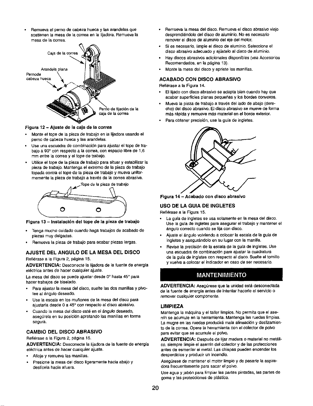
Remuevael perno de cabeza hueca y lasarandelas que
sostienen la mesa de la correa en la lijadora. Remueva la
mesa de la correa.
Cajade lacorrea
Arandela
Pernode
cabeza hueca
ijacidn de la
¢aja de la correa
Figura 12 - Ajuste de la caja de la correa
Monte el topede la pieza de trabajoen Is lijadorausandoel
perno de cabeza hueca y las arandelas.
Use una escuadrade combinacidnpara ajustarel topede tra-
bajoa 90° con respectoa lacorrea,con espaciolibrede 1,6
mm entre la correay el tope de trabajo.
• Utiliceeltope de la plazade trabajopars situary estabilizarla
pieza de trabajo. Mantenga el extremo de la pieza de trabajo
topada contra el tope de la plaza de trabajo y mueva unifor-
memente la pieza de trabajo a travOsde la correa abrasiva.
• Remueva la mesa del disco. Remueva eJ disco abrasivo viajo
desprendi_ndolo del disco de aluminio. No es necesario
remover el disco de aluminio del eje del motor.
• Si es necesario, limpie el disco de aluminio. Selecciona el
disco abrasivo adecuado y ajOstelo al disco de aluminio.
• Hay discos abrasivos adicionales disponibles (vea Accesorios
Recomendados, en la p_,gina 13).
• Monte la mesa del disco y apriete las msnil[as.
ACABADO CON DISCO ABRASlVO
Refi_rase a la Figura 14.
• El lijadocon discoabrasivose adapts biencuandohay que
acabar superficiesplanas peque_as y losbordesconvexos.
• Mueva la piezade trabajoa travSsdel lado de abajo(dere-
cho) del discoabrasivo. El discoebrasivo se mueve de forma
mds r_piday remuevem_s materialen el bordeexterior.
• Paraobtener precisibn,use la guia de ingletes.
O O
Flgura 13 - Instalacldn del tope de la pieza de trabajo
• Tengs mucho cuidado cuando hags trabajos de acabado de
piezas muy delgadas.
Remueva la pieza de trabajo pars acabar piezas largas,
AJUSTE DEL ANGULO DE LA MESA DEL DISCO
Refi_rase a la Figura 2, pdgina 15.
ADVERTENCIA: Desconectela lijadorade la fuentede energfa
el_ctrica antes de hacercualquierajuste.
La mesa del disco se puede ajustar desde 0° hasta 45° pars
hacer trabajos de biselado.
Pars ajustarla mesa del disco, suelte las dos menillas y pivo-
tee al dngulo deseado.
Use Is escals en los mu_ones de la mesa del disco pars
ajustarla desde 0 a 45° con respecto al disco abrasivo.
Cuando la mesa del disco estd en el dngulo deseado,
asegulrelaen su posicidn apretando las manillas en forma
segura.
CAMBIO DEL DISCO ABRASIVO
Refi_rasea la Figura 2, pdgina 15.
ADMERTENClA: Desconecte la Jijadorade la fuente de energia
el_ctrica antes de hacer cualquier ajusta.
Afloje y remueva las manillas.
Presione la mesa del disco ligeramente hacia abajo y
deslfcela hacia afuera.
Figura 14 - Acabado con disco abraslvo
USO DE LA GUIA DE INGLETES
Refi_rase a la Figura 15.
La gu[a de ingletesse usa solamentaen la mesa del disco.
Use la gufade ingletespara asegurarel trabajoy mantenarel
bngulo correctocuandose lijacon disco.
Ajuste el _ngulo volviendoa colocarla escala de laguia de
ingletesy asegurdndoloen su lugarcon la manilla,
Revisela precisidnde la escalade la gufade ingletes.Use
una escuadrade combinacidnpara ajustar lacuadratura
de la gufa de ingletes con respecto al disco. Suelte el tornillo
y vuelva a colocar el indicadoren caso de ser necesario.
2O
ADVERTENCIA: AsegOreseque la unidadest_ desconectada
de lafuente de energla antesde intentarhacerleel servicioo
removercualquiercomponente.
LIMPIEZA
Mantenga la m&quina y el taller limpios. No permita que el ase-
rdn se acumule en la herramienta. Mantenga las ruedas limpias,
La mugre en las ruedas producir& mala alineacibn y deslizamien-
to de Jacorrea. Opere la herramienta con el colector de polvo
para evitar que se acumule el polvo.
ADMERTENCIA: Despu_s de lijar readers o material no met_li-
co, siempre limpie el aserdn del colector y de las protecciones
antes de esmerilar el metal. Las chispas pueden encender los
desperdicios y producir un incendio.
Aseg_rese de mantener el motor limpio y de pasarle la aspira-
dora frecuentementa para sacar el polvo.
Use agua y jabbn pars limpiar las partas pintadas, las partes de
goma y Iss protecciones de pldstico.

LUBRICACION
Los rodarnientosde bola protegidosque tiene esta lijadorahan
side lubricadospermanenternenteen la f_brica. No necesitan
lubricacidn adicional.
Cuando la operacibn parece dura, si se aplica una capa
livianade ceradel tipopara autorndvilesa la mesa de la
correay a ladel disco,se facilitar& la alimentacidndel tra-
bajo durante el acabado.
No apliquela ceraa la platinade la correa.La eorrea puede
recoger la cera y depositerla sobre las ruedas,haci_ndola
que se resbale.
MANTENGA LA HERRAMIENTA EN BUEN ESTADO
• Si el cordbn el_ctrico est_ desgastado, cortado o dai_ado,
c&mbielo inrnediatamente.
• Cambie los abrasivosdesgastadoscuandosea necesario.
• Cambie cualquierparte dafiada o que falte. Use la listade
partescuando las ordene.
Todointento de repararel motorpuede creer unpeligro,a rne-
nosque la reparacidnla haga unt_cnioode serviciecalificado.
El serviciode reparaci6nest&disponible en sutiendaSears
rn_s cernana.
21
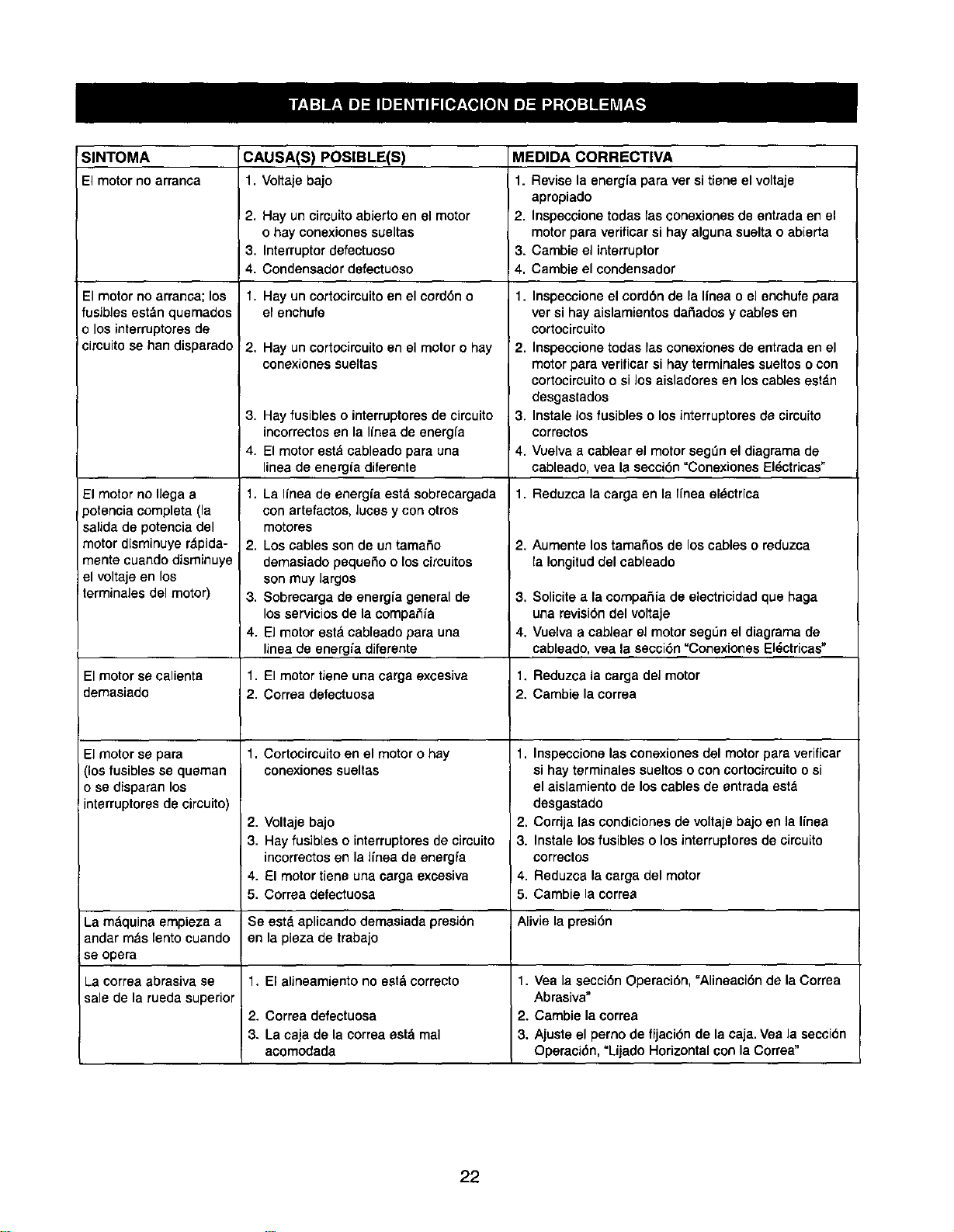
SINTOMA CAUSA(S) POSlBLE(S) MEDIDA CORRECTIVA
El motorno arranoa 1, Voltaje bajo 1. Revise la energfa para ver si tiene el voltaje
apropiado
2, Hay un circuitoabierto en el motor 2, Inspeccione todas las conexiones de entrada en el
o hay conexiones sueltas motorpara verificar si hay alguna suelta o abierta
3. Interrupter clefectuoso 3. Cambie el interrupter
4. Condensador defectuoso 4, Cambie el condensador
1, Hay un cortocircuitoen el cerd6n o
el enchufe
El motor no arranca; los
fusibles estdn quemados
o los interruptoresde
circuito se han disparado
El motor no llega a
)otencia completa (la
salida de potencia del
motor disminuye r_pida-
manta cuando disminuye
el voltaje en los
terminales del motor)
El motor se calienta
demasiado
El motor se para
(los fusibles se queman
o se disparan los
interruptores de circuito)
2. Hay un cortocimuitoen el motoro hay
conexiones sueltas
3. Hay fusibles o interruptoresde circuito
incorrectos en la linea de energfa
4. El motor est& cableado para una
linea de energia diferente
1. La Ifnea de energfa estd sobrecargada
con artefactos, luces y con otros
motores
2. Los cables son de un tamaSo
demasiado pequeSo o los circuitos
son muy largos
3. Sobrecarga de energfa general de
los servicios de la compaS/a
4. El motor est_lcableado para una
linea de energ/a diferente
1. El motor tiene una carga excesiva
2. Corraa defectuosa
1. Cortocircuito en el motor o hay
conexiones sueltas
2,
3.
Voltaje bajo
Hay fusibles o interruptores de circuito
incorrectos en la Ifnea de energfa
El motor tiene una carga excesiva
Correa defectuosa
1. Inspecsione el cord6n de la Ifnea o el enchufe para
ver si hay aislamientos daSados y cables en
cortocircuito
2. Inspeccione todas las conexiones de entrada en el
motor para verificar si hay terminales sueltos o con
cortocircuitoo si los aisladores en los cables estdn
desgastados
3. Instale los fusibles o losinterruptores de circuito
correctos
4. Vuelva a cablear el motorsegL_nel diagrama de
cableado, yea la secci6n =Conexiones El_ctricas"
1. Reduzca la carga en la Ifnea el_ctrica
2. Aumente lostamaSos de loscables o reduzca
la Iongitud del cableado
3. Solicite a la compaSia de eiectricidad que haga
una revisi6n del voltaje
4. Vuelva a cablear el motor segL_nel diagrama de
cableado, vea la secci6n "Conexiones El_ctricas"
1. Reduzca la carga del motor
2. Cambie la correa
1. Inspeccione las conexiones del motor para verificar
si hay terminales sueltos o con cortocimuitoo si
el aislamiento de los cables de entrada est_
desgastado
2. Corrija las condiciones de voltaje bajo en la l/nea
3. Instale los fusibles o losinterruptores de cimuito
correctos
Reduzca la carga del motor
Cambie la correa
4. 4,
5. 5.
La mdquina empieza a Se estd aplicando demasiada presi6n Alivie la presi6n
andar m_s lento cuando en la pieza de trabajo
se opera
La correa abrasiva se 1. El alineamiento no estd correcto 1. Vea la secci6n Operaci6n, "Alineaci6n de la Correa
sale de la rueda superior Abrasiva"
2. Correa defectuosa 2. Cambie la correa
3. La caja de la correa estd mal 3. Ajuste el perno de fijaci6n de la caja. Vea la secci6n
acomodada Operaci6n, "Lijado Horizontal con la Correa"
22

NOTAS
23

Your Home
For repair-in your home-of all major brand appliances,
lawn and garden equipment, or heating and cooling systems,
no matter who made it, no matter who sold itI
For the replacement parts, accessories and
owner's manuals that you need to do-it-yourself.
For Sears professional installation of home appliances
and items like garage door openers and water heaters.
1-800-4-MY-HOME ® (1-800-469-4663)
Call anytime, day or night (U.S.A. and Canada)
www.sears.com www.sears.ca
Our Home
For repair of carry-in items like vacuums, lawn equipment,
and electronics, call or go on-line for the location of your nearest
Sears Parts & Repair Center.
1 800 488 1222
Call anytime, day or night (U.S.A. only)
www.sears.com
To purchase a protection agreement (U.S.A,)
or maintenance agreement (Canada) on a product serviced by Sears:
1-800-827-6655 (U.S.A.)
Para pedir servicio de reparaci6n
a domicilie, y para ordenar piezas:
1"888-SU'HOGAR sM
(1-888-784-6427)
lm800"361--6665 (Canada)
i
Au Canada pour service en fran_ais:
1-800-LE-FOYER Mc
(1-800-533-6937)
www.sears.ca
....S_EAR,
iiiii!i!_ii_ii!
;i _
Registered Trademark/ TM Trademark/ SMServiceMark ofSears, Roebuckand Co.
O Marca Registrada/ TMMama de FSbrica/ sMMama de Setviciode Sears, Roebuckand Co.
MCMarquede commerce/ MOMarque d_posdede Sears, Roebuckand Co, © Sears. Roebuckand Co.

