Loading ...
Loading ...
Loading ...
Part Number 550-142-303/1120
23
EG
/
PEG sEriEs 6
•
EGH sEriEs 5 Gas-firEd boilErs — boilEr manual
For your safety, turn off electrical power supply at ser-
vice entrance panel before making any electrical con-
nections to avoid possible electric shock hazard. Fail-
ure to do so can cause severe personal injury or death.
Refer to the Control Supplement for additional
information, operating instructions and control
wiring diagram.
Wiring must be NEC Class 1 ANSI/NFPA 70 – latest
edition.
If rollout thermal fuse element wire supplied with
boiler must be replaced, type 200 °C wire or equiva-
lent must be used. If other original wiring supplied
with boiler must be replaced, use only type 105 °C
wire or equivalent.
Boiler must be electrically grounded as required
by National Electrical Code ANSI/NFPA 70 – latest
edition.
Electrical installation must comply with:
1. National Electrical Code ANSI/NFPA 70 – latest edition
and any other national, state, provincial or local codes or
regulations.
2. In Canada, CSA C22.1 Canadian Electrical Code Part 1, and
any local codes
Wiring connections
1. Boiler is shipped with controls completely wired, except
spill switch and vent damper. See wiring diagram in Control
Supplement for details.
2. Installer must attach wiring diagram inside jacket door.
3. See Figure 27 for field wiring. A separate 120VAC electrical
circuit with a fused disconnect switch (15 amp recommended)
should be used for the boiler.
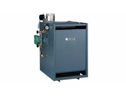
4. A strain relief bushing and adapter must be used at each point
where wiring passes through control case (see Figure 28) to
protect wiring insulation.
5. Multiple zones — Refer to zone valve manufacturer’s literature
for wiring and application. A separate transformer is required
to power zone valves. Zoning with circulators requires a relay
for each circuit.
Room thermostat
1. Connect thermostat as shown on wiring diagram on boiler.
2. Install on inside wall away from influences of drafts, hot or cold
water pipes, lighting fixtures, television, sunrays or fireplaces.
3. If thermostat has a heat anticipator, set heat anticipator in
thermostat to match power requirements of equipment con-
nected to it. Refer to the appropriate Control Supplement for
instructions on the thermostat anticipator setting.
Figure 28 Provide strain reliefs
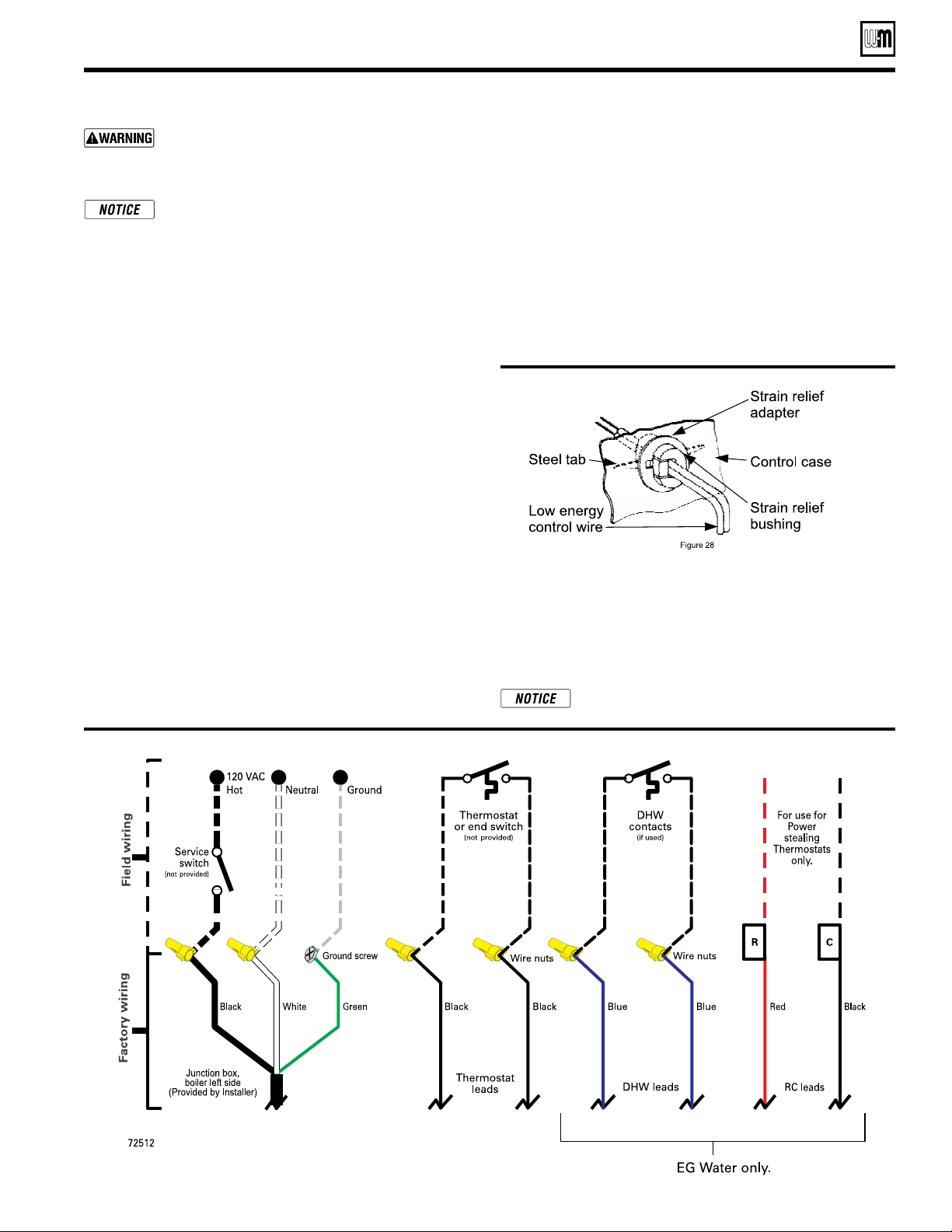
Connect eld wiring to boiler
Figure 27 Connect field wiring in boiler junction box as shown below. See Control Supplement for more details.
DHW (if used)
Connect the DHW aquastat as shown in wiring below. The
Economy function of the control is not utilized with DHW
input.
R & C Connections (if used)
24VAC leads should be used for power stealing thermostats only !
Other devices requiring 24VAC should have separate
power supply.
Loading ...
Loading ...
Loading ...