Loading ...
Loading ...
Loading ...
Part Number 550-142-303/1120
13
EG
/
PEG sEriEs 6
•
EGH sEriEs 5 Gas-firEd boilErs — boilEr manual
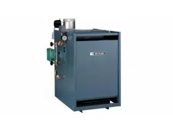
Figure 11 EG/EGH - Access panel
(Factory installed on PEG boilers)
Spill switch installation
EG 30 – EG 75 and PEG 30 – PEG 65 boilers only, fasten spill
switch to draft hood as shown on page 34, Drawing Ref. Letter “K”.
Connect wires as shown in the appropriate Control Supplement.
Damper installation
If damper will be installed, see Control Supplement for informa-
tion.
Breeching erection
Connect from draft hood or damper outlet to chimney or vent
with same size breeching. Where possible, vertical venting to the
outside from draft hood or damper outlet will offer best perfor-
mance. Where horizontal breeching is used, slope upward at least
1/4 inch per lineal foot toward chimney or vent and support with
hangers to prevent sagging.
A vertical height of 3 feet to 5 feet of breeching before
any elbow or horizontal breeching is recommended
to reduce chances of flue gas spillage at draft hood
on EGH-95 thru -125 boilers (not restricted on any
EG or EGH-85). Long horizontal breechings, exces-
sive numbers of elbows or tees, or other obstructions
which restrict the flow of combustion gases should
be avoided.
Breeching must not be connected to any portion of a mechanical
draft system operating under positive pressure.
Jacket installation (Factory installed on PEG)
1. Remove the proper knockout discs from panels as shown in
Table 4, page 10.
Tankless and storage heater knockouts must be
removed for EG and EGH boilers with optional
tankless heaters prior to jacket installation.
2. Follow Jacket Instructions in jacket carton.
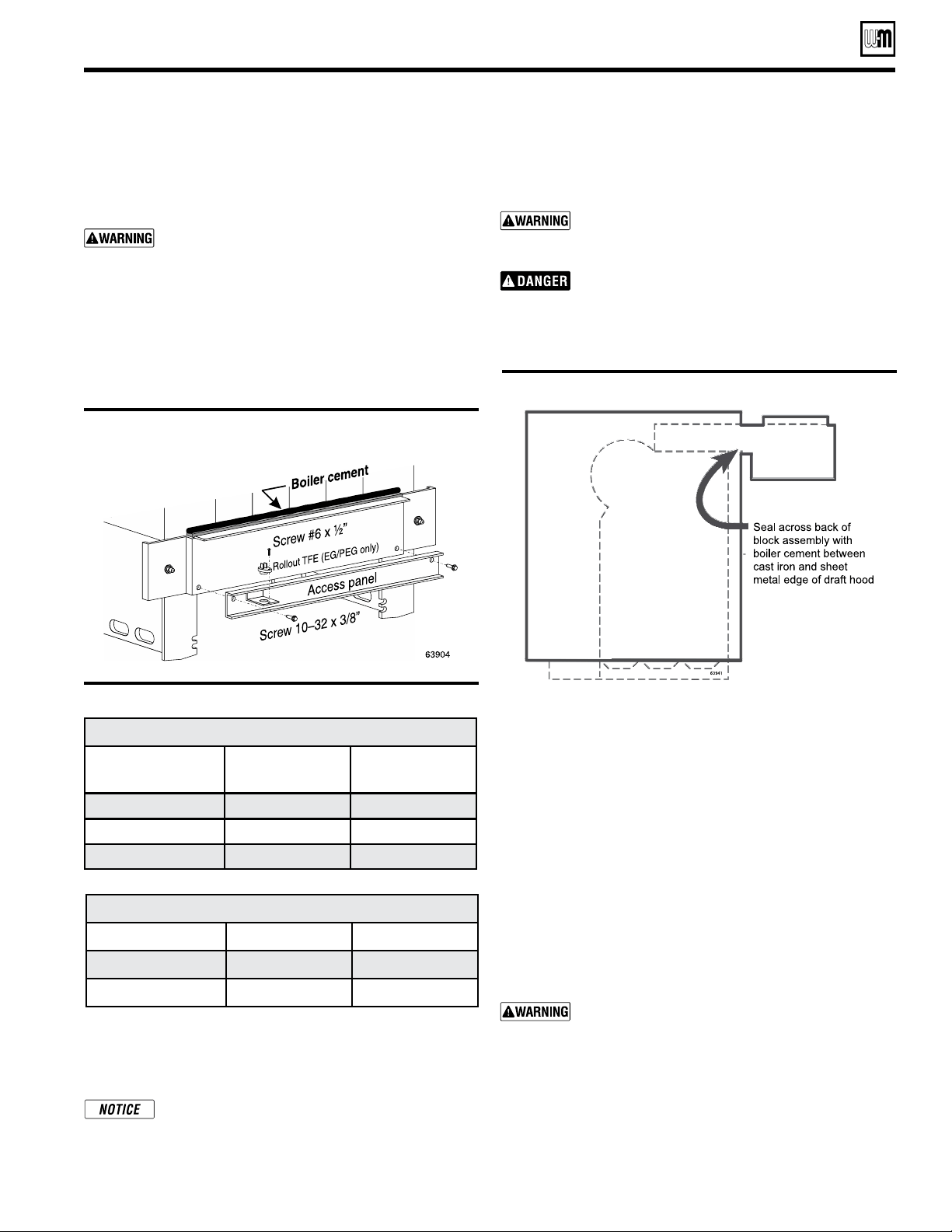
Figure 12 Draft hood
Prepare the boiler (continued)
Table 5 Orifice drill sizes
Draft hood installation
Attach draft hood to flue collector hood using #10 x 1/2” sheet
metal screws provided. Use boiler cement furnished to provide
gas tight seal.
Failure to maintain gas-tight seal can cause flue gas
spillage and carbon monoxide emissions, resulting
in severe personal injury or death.
Do not alter boiler draft hood or place any obstruc-
tion or non-approved damper in the breeching or
vent system. CSA certification will become void.
Flue gas spillage and carbon monoxide emissions
will occur causing severe personal injury or death.
Installation of base shield - EGH only
1. See Figure 8, page 12, slide base shield under burner drawer
assembly.
2. The flanged end of the shield should be located at the front
of the boiler.
The installer must install base shield, flanged
end of shield at front of boiler for proper boiler
operation.
Inspect burners – PEG boilers
1. PEG boiler are factory-assembled, but the burners and base
panels should be inspected to ensure they are in good condi-
tion.
2. Remove the access panel (Figure 11) and inspect the burners
per step 6 on page 11. Replace the access panel.
Orice Drill Sizes
Boiler Model Natural Gas Propane Gas
EG 30-65
2.35mm ------
EG 75
2.30mm ------
EGH 85-125
2.30mm 1.40mm
Orice Drill Sizes EG/PEG Canada Only
Elevation Natural
Propane
0-2,000 ft. 2.45mm ------
2,000-4,500 ft. 2.30mm ------
Loading ...
Loading ...
Loading ...