Loading ...
Loading ...
Loading ...
Part Number 550-142-303/1120
22
EG
/
PEG sEriEs 6
•
EGH sEriEs 5 Gas-firEd boilErs — boilEr manual
Connecting gas supply piping
1. Size gas piping considering:
a. Diameter and length of gas supplying piping.
b. Number of fittings.
c. Maximum gas consumption (including any possible future
expansion).
d. Allowable loss in gas pressure from gas meter outlet to
boiler. For pressure drops, see ANSI Z223.1/NFPA 54 –
latest edition. Canadian installations must comply with
Natural Gas and Propane Installation Code, CAN/CSA
B149.1 or B149.2 Installation Codes.
2. For natural gas:
a. Refer to Table 11 or the National Fuel Gas Code. To obtain
cubic feet per hour, divide the input by 1000.
b. Size for rated boiler input.
c. Inlet gas pressure: 5”
w.c. minimum
13”
w.c. maximum
d. Manifold gas pressure: 3¹⁄₂"
w.c.
e. Install 100% lock-up gas pressure regulator in supply line
if inlet pressure exceeds 13"
w.c., then adjust for 13" w.c.
maximum.
3. For propane gas:
a. Inlet gas pressure: 11”
w.c. minimum
13”
w.c. maximum
b. Manifold gas pressure: 10”
w.c.
c. Gas pressure regulator provided by gas supplier must be
adjusted for maximum pressure of 13”
w.c.
d. Contact gas supplier to size pipes, tanks and regulator.
4. Remove knock-out disc from jacket panel which gas supply
is to be piped.
5. Follow good piping practices.
6. Pipe joint compound (pipe dope) must be resistant to cor-
rosive action of liquefied petroleum gases. Apply sparingly
only to make threads of pipe joints.
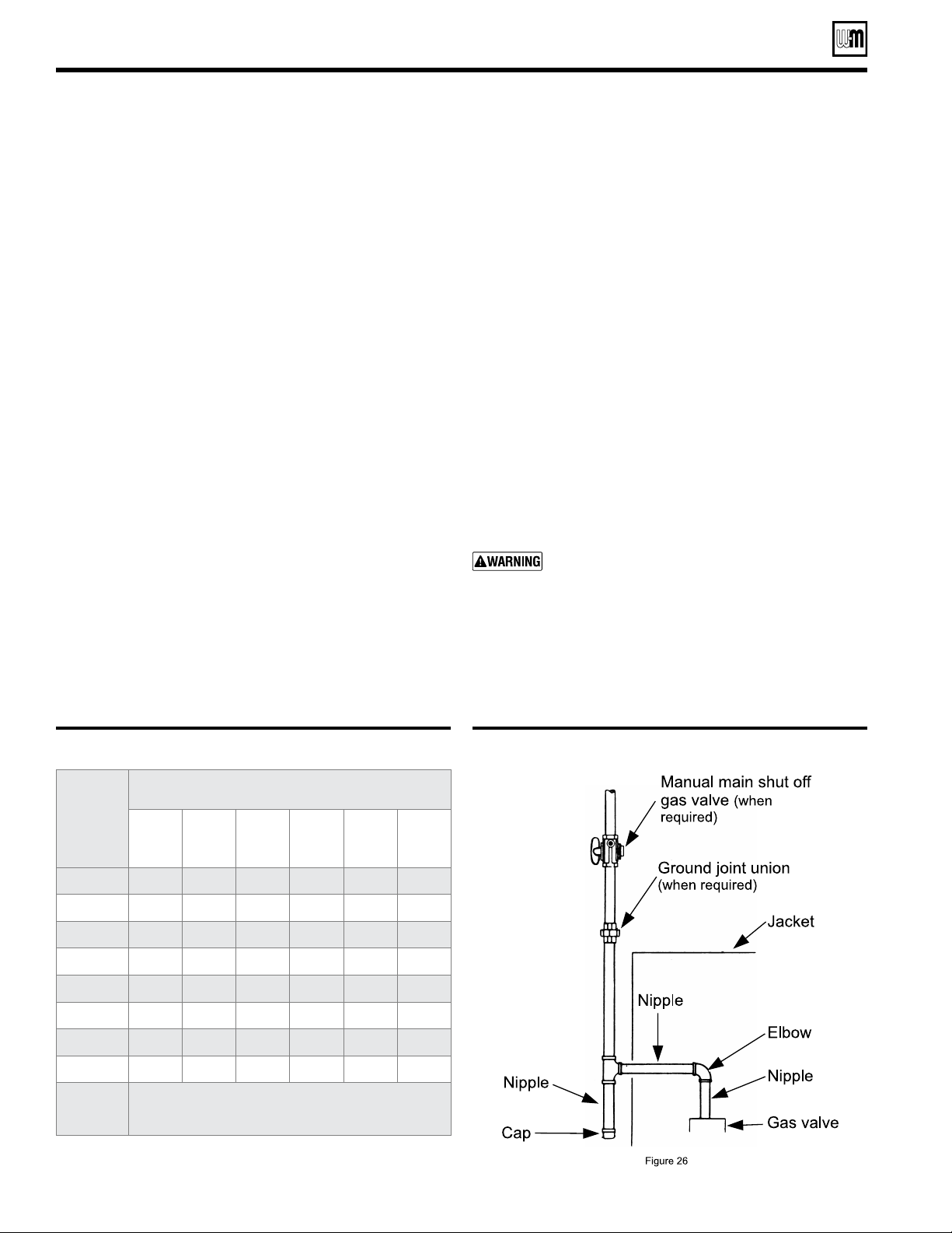
7. Install drip leg at inlet of gas connection to boiler. Where local
utility requires, extend drip leg to floor.
8. Install ground joint union when required for servicing. See
Figure 26.
9. Install manual shut-off valve outside boiler jacket as shown
in Figure 26 when required by local codes.
10. Support piping by hangers, not by boiler or its accessories.
11. In Canada only, the manual main shut off valve (when used)
must be identified by the installer.
12. Purge all air from piping.
13. Before placing boiler in operation, check boiler and its gas
connection for leaks.
Do not check for gas leaks with an open flame – use
bubble test. Failure to do so can cause severe per-
sonal injury, death or substantial property damage.
a. Close manual main shut-off valve during any pressure testing
at less than 13 inches water column.
b. Disconnect boiler and gas valve from gas supply piping during
any pressure test greater than 13 inches water column.
Figure 26 Gas supply piping
Connect gas supply piping
Table 11 Gas pipe capacities
Adjusted
length
of gas
supply
piping in
feet *
Capacity of pipe for pipe sizes in
cubic feet of gas per hour **
½” ¾” 1” 1¼” 1½” 2”
10 132 278 520 1050 1600 3050
20 92 190 350 730 1100 2100
30 73 152 285 590 860 1650
40 63 130 245 500 760 1450
50 56 115 215 440 670 1270
75 45 93 175 360 545 1020
100 38 79 150 305 460 870
150 31 64 120 250 380 710
Notes:
*
Include measured length of gas supply piping and allowance
in feet for number and size of ttings.
**
Specic Gravity - 0.60; Pressure loss - 0.30” w.c.
Loading ...
Loading ...
Loading ...