Loading ...
Loading ...
Loading ...
Part number 550-100-400/0119
70
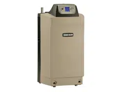
Figure 74 ole preparation in all eil-cLain ent
air plate
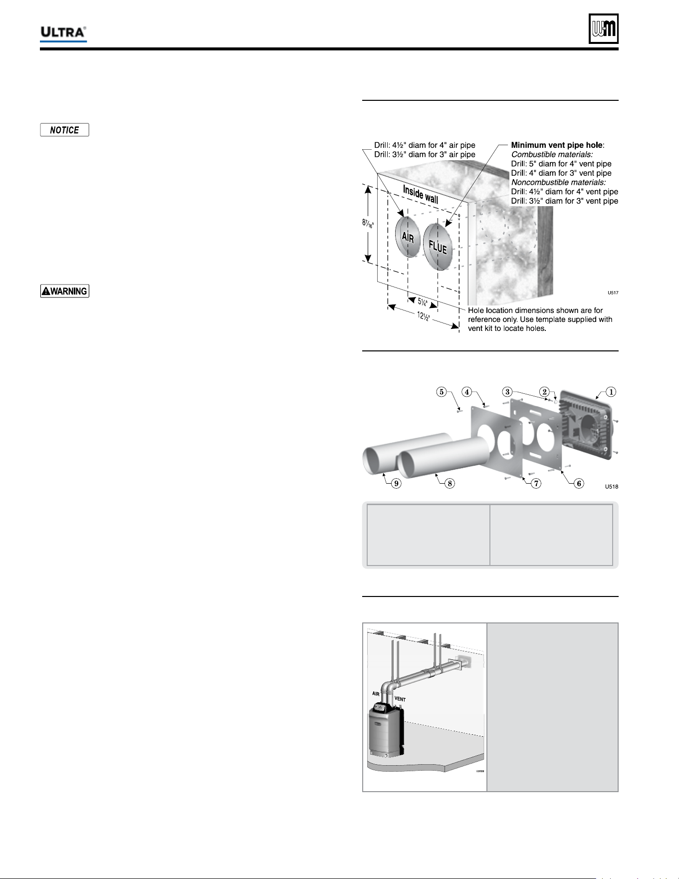
Figure 75 Termination asseml eil-cLain ent
air plate
1 Vent termination (3” or 4”)
2 Lock washer, #10 (4)
3 Sheet metal screw, #10 x ½” (4)
4 Plastic wall anchor (8)
5 Sheet metal screw, #10 x 1¼” (8)
6 Outer mounting plate
7 Inner mounting plate
8 Vent pipe (butt to screen in termina-
tion)
9 Air pipe (butt to stops in termina-
tion)
Figure 76 Install termination plate
Install pipe supports every 5
feet on both the horizontal and
vertical runs.
Install a hanger support within
6 inches of any upturn in the
piping.
The Weil-McLain plate
termination must be installed
before piping from the boiler to
the termination.
Slope horizontal piping
downward toward the boiler at
least 1/4 inch per foot.
®
Series 4
gas-fired water boiler — Boiler Manual
Sidewall vent/air termination: Weil-McLain cap (cont.)
Install terminations — Weil-McLain vent/air cap
The inside and outside cover plates are stamped to
identify the exhaust (vent) and intake (air) openings.
Make sure to orient the plates correctly.
1. Locate termination opening and avoid obstructions:
a. Use the template supplied with the termination kit.
b. Locate the template on the outside building surface where
the penetration is to be made.
c. Make sure there will be no obstructions that might prevent
proper placement of the termination.
d. Use the template to mark the locations for the four mount-
ing holes, fl ue pipe and air pipe. Level the template with a
spirit level.
For the Weil-McLain plate, the template must be level
to ensure the fl ue and air pipe will be side-to-side, as
shown in Figure 74 . Failure to comply could result in
severe personal injury, death or substantial property
damage.
e. Cut holes in the wall as shown in Figure 75 , using the location
marks made with the template. For best results, use a small-
diameter, long drill bit to drill centering holes for the fl ue and
air pipe openings. Then drill the large openings from both
the inside and outside.
f. The fl ue pipe and air pipe may be run through a rectangular
cutout (as marked on the template) in lieu of two separate
holes if desired.
2. Drill holes for the screws or plastic anchors to secure the outside
plate. Install the outside plate and mount the termination on the
plate (temporarily).
a. Cut the fl ue pipe so the extension through the wall will cause
the vent pipe to fully extend into the termination socket.
b. Cut the air pipe so the extension through the wall will butt
the air pipe against the stops inside the termination.
c. When using 3-inch vent piping with a 4-inch termination
(Ultra-230 applications), increase the fl ue pipe size to 4 inch
before the pipe passes through the wall. This is required to
obtain a seal between the fl ue pipe and the termination.
d. Temporarily slide the flue and air pipes through the
opening(s). Slide the inside wall plate over the two pipes and
into position on the inside wall.
e. Position the inside plate so the fl ue pipe and air pipe slope
downward slightly toward the boiler (1/4” per foot).
f. Mark the four (4) mounting holes for the plate.
g. Remove the vent and air pipe, drill the four mounting holes,
and mount the inside plate.
3. Test fi t the vent/air termination on the vent pipe. Make sure the
vent pipe fully penetrates the termination socket and the air pipe
butts against the interior stops.
4. Apply silicon RTV sealant to the interior of the vent termination
and slide onto vent pipe. Rotate slightly to spread the silicon to
ensure a tight seal around the vent pipe.
5. Secure the termination in place using the four (4) #10 x ½” sheet
metal screws and lock washers (see Figure 75 ).
Loading ...
Loading ...
Loading ...