Loading ...
Loading ...
Loading ...
Part number 550-100-400/0119
63
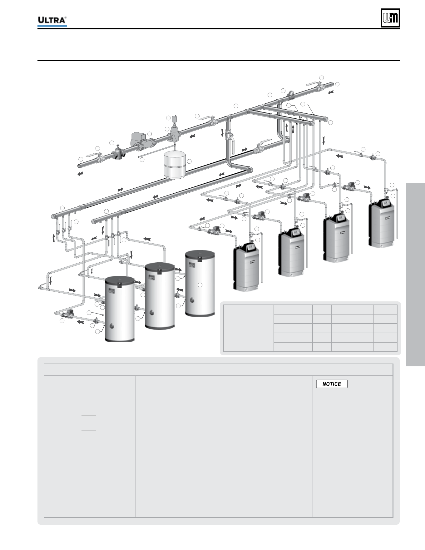
Figure 64 ipin laout tpical pipin for multiple Ultra oilers ith storae heaters -oiler sstem
Suggested DHW
boiler-side pipe
sizing
(for max 0.04
feet head loss per foot of
total equivalent length,
TEL)
Flow rate Size Flow rate Size
1 – 3.9 gpm ¾” 24 – 45 gpm 2”
3.9 – 7.1 gpm 1” 45 – 75 gpm 2½”
7.1 – 16 gpm 1¼” 75 - 140 gpm 3”
16 – 24 gpm 1½” 140 – 290 gpm 4”
Multiple boiler installations (continued)
®
Series 4
gas-fired water boiler — Boiler Manual
Legend — Figure 64
1 Flow/check valve (each boiler)
2 Isolation valves (when used)
3 Caps
4 Easy-Fit® Manifold (supply) — layout
and size per page 60
5 Easy-Fit® Manifold (return) — layout
and size per page 60
6 Primary circulator
7 Expansion tank (diaphragm type)
8 System air eliminator
9 System automatic air vent
13 Cold water supply
17 Boiler circulator (each boiler)
18 System supply
19 System return
20 Boiler relief valve and discharge piping,
installed per Ultra Boiler Manual
21 Indirect-fi red storage water heaters (Weil-McLain AQUA PLUS shown) — Example
is shown with reverse-return boiler-side piping using a single circulator. Alternate:
each water heater could have its own circulator.
22 Boiler water inlet
23 Boiler water outlet
24 DHW boiler-side circulators
25 DHW boiler-side supply Easy-Fit® Manifold
26 DHW boiler-side return Easy-Fit® Manifold
27 Flow/check valves (to prevent induced or gravity fl ow in heating system or DHW
piping)
28 Check valve to prevent heat migration in heating system.
29 See water heater manual for DHW piping — The DHW piping must also be mani-
folded together since the boiler-side piping is manifolded. If DHW heaters supply
separate DHW circuits, provide an individual circulator for each water heater, and
control each circulator by its water heater’s aquastat.
30
Strap system supply and return sensors to lines as shown, at least 6 pipe
diameters (but no more than 3 feet) from boiler connection tees.
31 Temperature/pressure gauge
This piping is sug-
gested only. The
layout above should be controlled
with a boiler sequencing panel that
provides DHW operation as well.
Wire the heating system circulator
to operate only on call for heat. Al-
ternatively, use the boiler sequencing
panel to provide domestic priority
by disabling the heating system cir-
culator any time there is a DHW call
for heat. The boiler circulators, item
17, must operate on any call for heat,
whether heating system or DHW.
Offset the DHW boiler-side supply
and return manifolds as shown so
the total run of pipe and fi ttings to
each of the water heaters is approxi-
mately equal.
6TQ
À>
Û>ÛiÃ
Loading ...
Loading ...
Loading ...