AirWash Whisper Manual 2019_1
Table of Contents
Rules for Safe Installation and Operation ..1
Shipping and Packing List ..........................1
Specifications .............................................2
Introduction .................................................2
General Information ....................................3
Product Application Guidelines ..................3
Parts Identification ......................................4
Physical Dimensions of Units .....................5
Dealer Installation Instructions ................. 6-8
Operation....................................................9
Maintenance...............................................9
Filter Change Schedule...............................9
Filter Changing Guidelines..........................9
Dealer Filter Change Instructions..............10
Dealer Motor Assembly
Replacement Instructions...............11
Electrical Diagram.....................................11
Replacement Parts...................................12
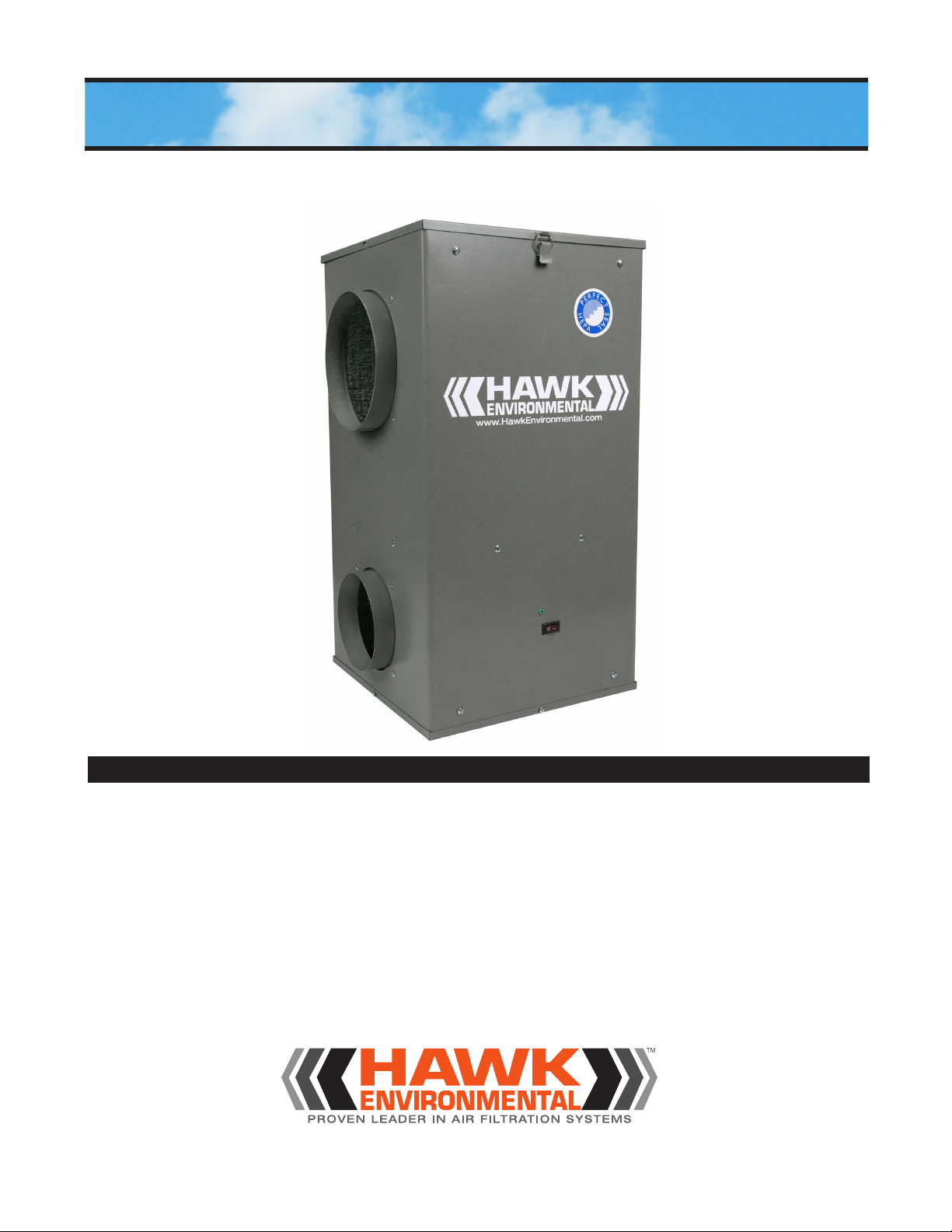
HOMEOWNERS MANUAL & DEALER INSTALLATION INSTRUCTIONS
AirWash
®
Whisper
AirWash Whisper Manual 2019_1
1
READ AND SAVE
THESE INSTRUCTIONS!
Please read instructions before installing and using the
HEPA Bypass Air Filtration System (HEPA system).
This will help you obtain the full benefit of the HEPA
system you have selected. It will also help you to
avoid needless service costs.
1. Read this manual carefully. Failure to follow these
rules and instructions could cause a malfunction of
the air filter or unsatisfactory performance and could
void your warranty.
2. Follow a regular service and maintenance schedule
to ensure efficient operation.
3. For safety and optimized performance of your HEPA
system, all installation and maintenance must be
performed by a professional heating and ventilation
contractor. The installer should be made aware
of your indoor air quality situation and be familiar
with your heating, ventilation and air conditioning
equipment.
4. High particulate distribution may occur during initial
start-up of this product, after installation, or after
VFKHGXOHG¿OWHUFKDQJHV,QGLYLGXDOVZKRDUHKLJKO\
sensitive to airborne particulates should not be in the
building, and allow 24 hours of operation for removal
of particulates from occupied spaces before re-entry.
Rules for Safe Installation and Operation
Shipping and Packing List
Risk of property damage, injury or death.
Installation, adjustments, alterations, service and
maintenance must be performed by a qualified
technician.
!
WARNING
Risk of Carbon Monoxide Poisoning.
Can cause injury or death.
Do not operate equipment without access panel in
place. Operation of this equipment without all access
panels in place may cause gas fumes from the
heating system to be drawn into occupied spaces.
!
WARNING
Package 1 of 1 contains:
1 - HEPA System
1 - Complete Filter Set (Packed inside Unit)
1 - Installation Instructions (this manual)
1 - Registration Card
HEPA System Models
Model AirWash Whisper-350 (AWW-350) is
designed to filter air up to a rate of 350 cfm.
Model AirWash Whisper-675 (AWW-675) is
designed to filter air up to a rate of 675 cfm.
Electrical Shock Hazard.
Can cause injury or death.
Disconnect all electrical power supplies
before servicing.
Do not operate equipment without ac-
cess panels in place.
!
WARNING

AirWash Whisper Manual 2019_1
Specifications
AWW-350 AWW-675
Nom. Air Flow @ 120VAC @ 0.0” E.S.P. 350 cfm 675 cfm
Weight (max - unpackaged) 30 lbs. 33 lbs.
Supply Voltage 120 VAC 120 VAC
Nom. Measured Power Consumption 125 Watts 225 Watts
Motor Current Draw - Total 1.0 amps 1.8 amps
Air Intake Collar (max) 8”-round 10”-round
$LU2XWÀRZ&ROODUPD[´URXQG ´URXQG
Operating Temp. Range - Return air (ºF) 30 to 95 30 to 95
+(3$¿OWHUHI¿FLHQF\ #PLFURQSDUWLFOHV
Ambient temperature range: -40ºF to 130ºF
Introduction
Congratulations! You will quickly realize that
you have purchased a very effective air cleaning
system. It incorporates state of the art HEPA
(High Efficiency Particulate Air) technology.
Your Hawk Environmental HEPA system comes
with a limited warranty. With proper attention
to its care and maintenance, you will receive
optimum performance.
If your indoor air has abnormally high
concentrations of particulates, the life span of
the filter media may be shortened. Excessive
particulates in the air will reduce the expected
life of the HEPA filter. Under normal conditions
the HEPA filter will last from two to five years.
The optional activated carbon canister has a
finite limit as to the amount of odor or other
gaseous volatile organic compounds (VOC) that
it can adsorb. The higher the concentrations,
the shorter the expected life. Higher humidity
may shorten the life of the carbon canister.
Under normal conditions, the carbon canister
should last up to 12 months.
,QLWLDOO\ WKH +(3$ ¿OWHU¶V SDUWLFXODWH UHPRYDO
HI¿FLHQF\LPSURYHVZLWKXVH+RZHYHUWKHDLU
ÀRZWKURXJKWKH+(3$¿OWHUPHGLDZLOOGHFUHDVH
DVGXVWEXLOGVXSRQWKH¿OWHUWKXV ORZHULQJLWV
ability to circulate and clean as much air as when
LW ZDV QHZ ,I WKH DLU ÀRZ WKURXJK \RXU XQLW LV
QRWLFHDEO\UHGXFHG\RXFDQLQVSHFWWKHSUH¿OWHU
DQG+(3$¿OWHUWRVHHLIWKH\VKRXOGEHUHSODFHG
5HSODFHPHQWRUZDVKLQJLIIRDPRIWKHSUH¿OWHU
every 3 months will help extend the life of the
+(3$¿OWHU
Please contact your local Hawk Environmental
GHDOHU UHJDUGLQJ UHSODFHPHQW RI ¿OWHU PHGLD
warranty information or if you have any questions
or concerns about the performance of your HEPA
system.
127( 7KLV ¿OWUDWLRQ V\VWHP LV DQ
$'',7,21$/¿OWHUDQGGRHV127UHSODFHWKH
H[LVWLQJDLUKDQGOHUIXUQDFHV\VWHP¿OWHU
2

AirWash Whisper Manual 2019_1
Media Filters
Media filters strain particulates from the air. The filter
media needs to have tiny holes to allow air to pass
through, but not particulates. Filter types vary for all
sorts of purposes. The most effective and proven filter
PHGLDLV+(3$+(3$ILOWHUPHGLDLVHIILFLHQW
at capturing particles which are 0.3 micron in size or
larger.
Carbon Filters
Carbon media is used to capture chemicals and odors,
also referred to as VOC. Chemicals and odors cannot
be captured with media type filters. Activated carbon
collects chemicals and odors in a process called
adsorption. If air passes through the carbon filter
before particulates are removed, the surface of the
carbon quickly gets covered with particulates, rendering
it ineffective at capturing chemicals and odors. If
particulates are removed from the air with a HEPA filter,
virtually the entire surface area of the carbon can be
used to capture chemicals and odors. This increases
the efficiency and filter life of the carbon filter.
Separate HEPA and Carbon Filters
HEPA and carbon filters have different life spans. It
is important for a filtration system to keep the filter
components independent from each other, so that
the filter that is dirty/saturated can be changed. This
is more economical than a system where you need
to throw out two or three filters when only one needs
changing.
The HEPA System’s 3 Stage Filtration Process
7KH VWDJH ¿OWUDWLRQ SURFHVV LV XVHG WR FUHDWH DQ
HIIHFWLYH¿OWUDWLRQV\VWHP(DFK¿OWHULVLQGHSHQGHQWDQG
can be changed individually.
• Stage 1: 3UH¿OWHU 7KH LQH[SHQVLYH IRDP
SUH¿OWHUUHPRYHV ODUJHU SDUWLFXODWHVIURP WKH DLU WKXV
SURORQJLQJWKHOLIHRIWKH+(3$¿OWHU
• Stage 2: +(3$ 7KH +(3$ ¿OWHU UHPRYHV
RI SDUWLFXODWHV PLFURQ DQG ODUJHU 7KH
FOHDQHGDLUWKHQSDVVHVWKURXJKWKHWKLUGVWDJH¿OWHU
• Stage 3 &DUERQ 7KH FDUERQ ¿OWHU LV DERXW
1/2 an inch thick to give it plenty of surface area for
UHPRYLQJFKHPLFDOVDQGRGRUVIURPWKHDLU7KLV¿OWHU
may be replaced by an optional heavy duty granular
carbon canister for maximum removal of chemicals and
odors. The clean air is then reintroduced into the air you
breathe.
General Information
Product Application Guidelines
Size of House vs. Air Changes per Hour
* Chart based on homes with 8 ft. ceilings.
Notes:
• Industry experience indicates that one (1) air change per hour generally provides adequate
air cleaning. Actual results will depend on multiple factors such as outdoor particulate
levels, infiltration rate, indoor activities, etc.
• Generally speaking, the more air changes per hour provided, the more effective a HEPA
system will be. People with sensitivities may desire a higher number of air changes per hour
for cleaner air.
Size of House*
Model 1,000 ft2 1,200 ft2 1,500 ft2 1,800 ft2 2,000 ft2 2,500 ft2 3,000 ft2 3,500 ft2
Unit (8,000 ft3) (9,600 ft3) (12,000 ft3) (14,400 ft3) (16,000 ft3) (20,000 ft3) (24,000 ft3) (28,000 ft3)
Model AWW-350 2.4 2.0 1.6 1.4 1.2 1.0 0.8 0.7
Model AWW-675 5.0 4.2 3.4 2.8 2.5 2.0 1.7 1.5
3
AirWash Whisper Manual 2019_1
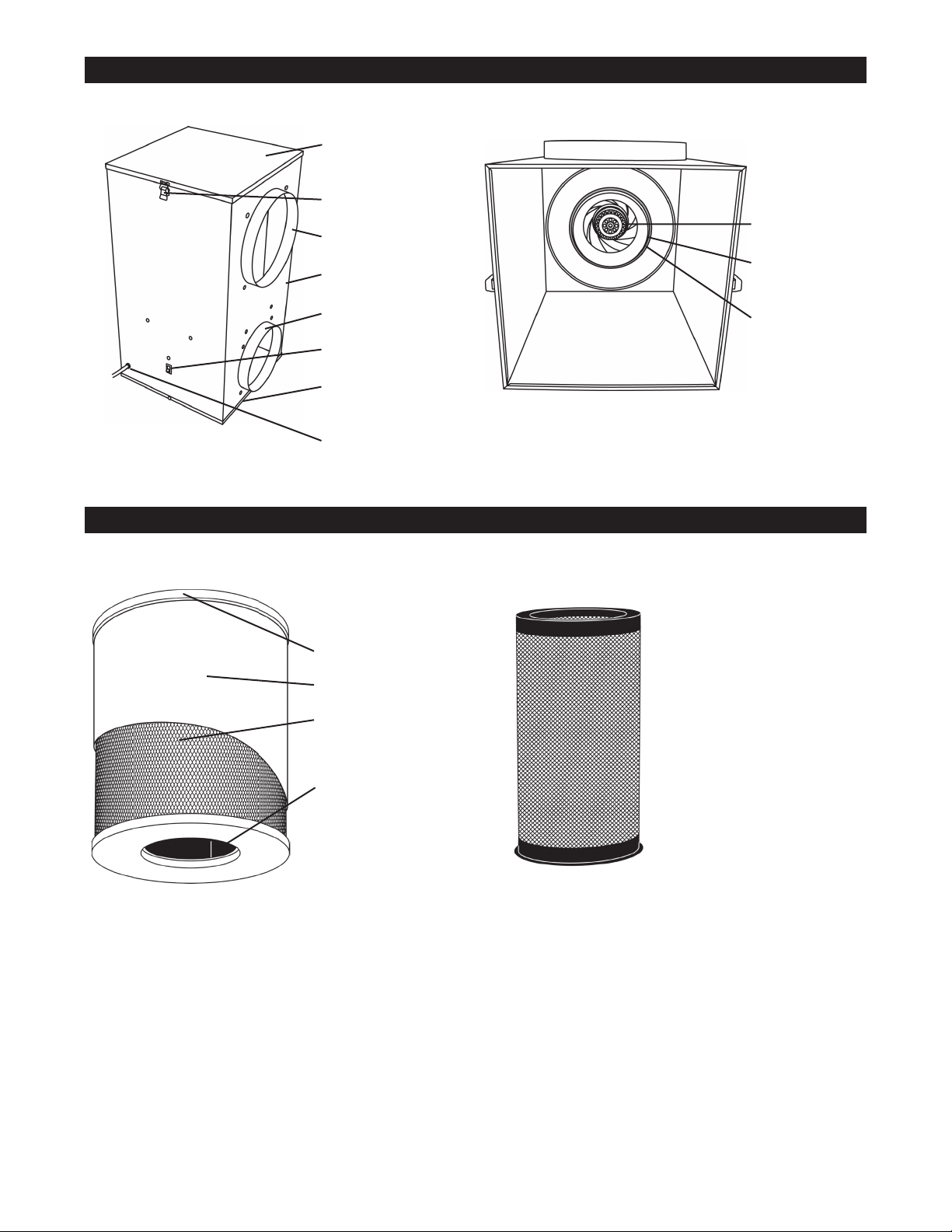
Parts Identification
Filter Section
Access Panel
Retaining Clips (2)
Intake Collar
Cabinet
2XWÀRZ&ROODU
On/Off Switch
Motor Section
Access Panel
Power Cord
Cabinet Parts
Inside Cabinet (Filter Section)
Figure 1
Figure 2
Motor/Impeller
Filter Adapter
(threaded)
µ2¶5LQJ
HEPA Filter
Pre-Filter - Foam
HEPA Filter Mesh
(Protects HEPA
Filter)
Inner Carbon Filter
For third stage increased
removal of chemicals
and odors.
Located inside the
HEPA filter.
Set aside inner carbon
¿OWHU ZKHQ XVLQJ WKH
optional carbon canister.
Optional Carbon Canister
HEPA Cartridge Parts
Figure 4
Figure 3.
Filter Parts Identification
4
AirWash Whisper Manual 2019_1
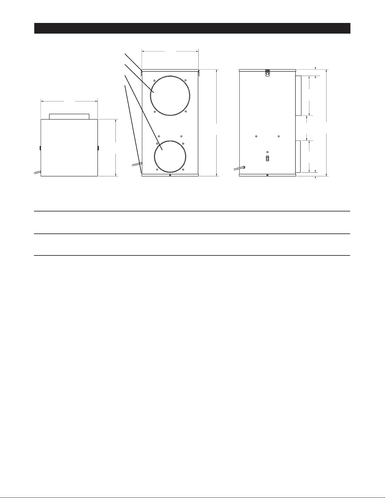
Physical Dimensions of Unit
E
G
C
F
A
A
A
MODEL NO. A B C D E F G
Model AWW-350 14.5 27.25 7.875 5.875 8.5 3 2
(368) (692) (200) (149) (216) (76) (51)
Model AWW-675 14.5 27.25 9.875 7.875 6.5 2 1
(368) (692) (251) (200) (165) (51) (32)
Dimensions in inches (mm)
Filter Section Access Panel
Air Intake
$LU2XWÀRZ
Motor Section Access Panel
Figure 5
B
B
D
5
AirWash Whisper Manual 2019_1
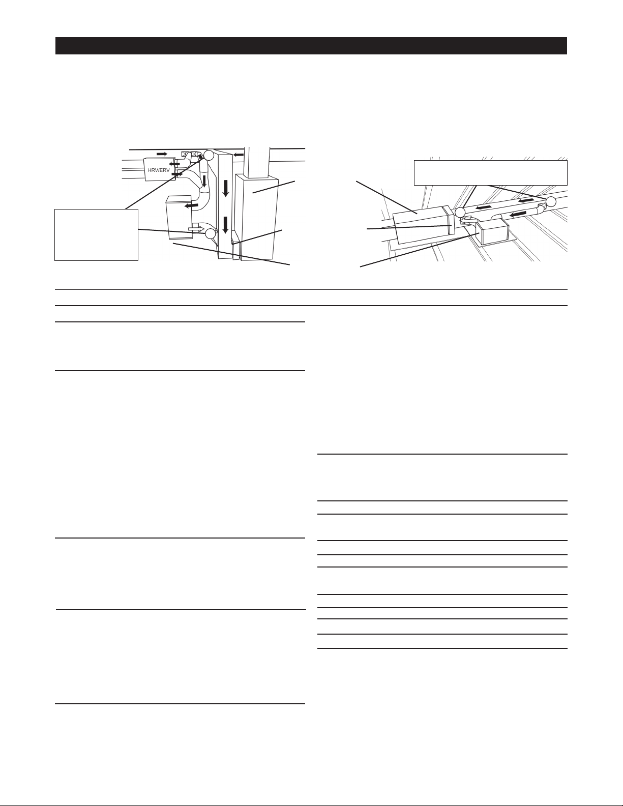
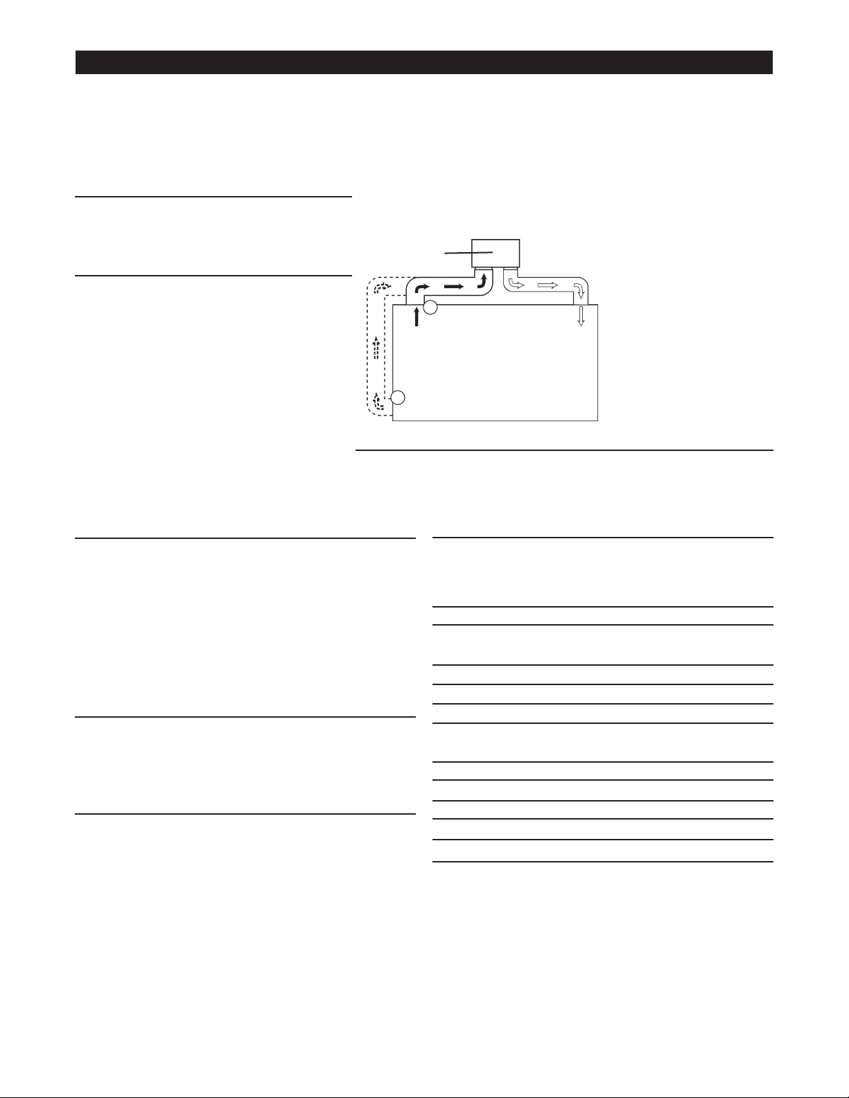
Typical Return to Return Application
For homes with horizontal forced air handler/furnace systems. (Air
handler/furnace is shown in an typical attic. See figure 7.)
Typical Return to Return Application
For homes with upflow forced air handler/furnace systems.(Air
handler/furnace is shown in a typical basement. See figure 6.)
Dealer Installation Instructions
Forced air handler/furnace systems:
The HEPA system should be installed as a bypass system, with part of the return ducted into the HEPA system. The filtered
air is then rerouted back into the return air, and continues through the system to be heated/cooled.
Figure 6
Figure 7
Preparation:
Here are some things to consider as you decide where to
install the HEPA system.
Location:
• Make sure there is room to open the HEPA filter access
panel for filter changes/inspections.
• Keep the HEPA system in a location where you can still
access the air handler/furnace filter.
• Keep the HEPA system away from possible water
damage.
• Vibration pads will reduce vibration for installations where
the unit is placed on the floor.
• Install HEPA system on floor or suspended platform. If
the unit is suspended, screws must not penetrate through
the cabinet. Make sure that you have the proper chains/
straps/joists and equipment to keep unit secure.
Intake0DUNHGDVµ$LU,Q¶RQXQLW
• Intake ducts should be installed upstream of any
humidifiers and be installed on the main return.
• Intake duct should be installed at least 6 ft. away from the
outflow duct on the main return.
Outflow0DUNHGDVµ&OHDQ$LU2XW¶RQXQLW
• Outflow duct should be installed as close to the air
handler/furnace inlet as possible but not directly into the
return air elbow of the main return.
• If the unit is being installed independently of any other
system, room diffusers are recommended to help
distribute airflow evenly in the occupied space.
Ducting:
,I+(3$V\VWHPLVLQVWDOOHGZKHUHLQOHWDQGRXWÀRZFROODUV
face down, metal elbows must be connected to both inlet
DQGRXWÀRZFROODUV
• Each connection must be sealed with aluminum tape or
mastic, including all take offs.
• Installed duct runs should be as straight as possible (if the
duct runs are too long, reduced CFM may result).
• If duct is exposed to unconditioned air, externally insulated
ÀH[GXFWLVKLJKO\UHFRPPHQGHG
([WHUQDOO\LQVXODWHGÀH[GXFWFDQDOVREHXVHGIRUQRLVH
reduction purposes.
• For best indoor air quality, do not use ductboard or
¿EHUJODVVLQVLGHRIGXFWV
Electricity:
• The unit must be plugged into a grounded 120V, 60Hz
outlet.
Required Materials for Installation of Unit:
Items for AWW-350
Flex or rigid duct 8” round & 6” round
(length as required)
Takeoffs One 8” & One 6”
Items for AWW-675
Flex or rigid duct 10” round & 8” round
(length as required)
Takeoffs One 10” & One 8”
All Models
Aluminum tape or mastic as required
0LVFKDQJLQJPDWHULDOV¿HOGSURYLGHG
NOTE: Be sure to review ‘Rules for Safe Installation and
Operation’ on page 1 of this document before start-up of
this unit.
A
A
B
B
Air Handler/
Furnace
Air
Handler/Furnace
Filter
HEPA System
NOTE: This filtration system is an ADDITIONAL filter, and does NOT replace the existing air handler/furnace system filter.
Distance between
A and B should be
¶WR¶IRUEHVW
results
Distance between A and B should
EH¶WR¶IRUEHVWUHVXOWV
6
AirWash Whisper Manual 2019_1
Preparation:
Here are some things to consider as you decide
where to install the HEPA system with an
HRV/ERV.
Location:
• Make sure there is room to open the
HEPA filter access panel for filter changes/
inspections.
• Keep the HEPA system in a location where
you can still access the air handler/furnace
filter.
• Keep the HEPA system away from possible
water damage.
• Vibration pads will reduce vibration for
installations where the unit is placed on the
floor.
• Install HEPA system on floor or suspended platform. If
the unit is suspended, screws must not penetrate through
the cabinet. Make sure that you have the proper chains/
straps/joists and equipment to keep unit secure.
Intake0DUNHGDVµ$LU,Q¶RQXQLW
• Most HRV/ERV systems will not move as much air as the
HEPA system. For these systems, install an additional
return from another treated air source into the HEPA
system.
• If using an additional return duct, it should be installed
upstream of any humidifiers. The fresh air outflow of
the HRV/ERV should be “Y” connected to the additional
return duct, then connected to the inlet of the HEPA
system.
• The additional return duct (if any) should be installed at
least 6 ft. away from the outflow duct on the main return.
• Duct both the HRV/ERV and the additional return into the
intake of the HEPA system.
Outflow0DUNHGDVµ&OHDQ$LU2XW¶RQXQLW
2XWÀRZ GXFW VKRXOG EH LQVWDOOHG DV FORVH WR WKH DLU
handler/furnace inlet as possible but not directly into the
return air elbow of the main return.
Ducting:
,I+(3$V\VWHPLVLQVWDOOHGZKHUHLQOHWDQGRXWÀRZFROODUV
face down, metal elbows must be connected to both inlet
DQGRXWÀRZFROODUV
• Each connection must be sealed with aluminum tape or
mastic, including all take offs.
• Installed duct runs should be as straight as possible (if the
duct runs are too long, reduced CFM may result).
• If duct is exposed to unconditioned air, externally insulated
ÀH[GXFWLVKLJKO\UHFRPPHQGHG
([WHUQDOO\LQVXODWHGÀH[GXFWFDQDOVREHXVHGIRUQRLVH
reduction purposes.
• For best indoor air quality, do not use ductboard or
¿EHUJODVVLQVLGHRIGXFWV
Electricity:
• The unit must be plugged into a grounded 120V, 60Hz
outlet.
Required Materials for Installation of Unit:
Items for AWW-350
Flex or rigid duct 8” round & 6” round
(length as required)
Takeoffs One 8” & One 6”
Items for AWW-675
Flex or rigid duct 10” round & 8” round
(length as required)
Takeoffs One 10” & One 8”
All Models
Aluminum tape or mastic as required
0LVFKDQJLQJPDWHULDOV¿HOGSURYLGHG
NOTE: Be sure to review ‘Rules for Safe Installation and
Operation’ on page 1 of this document before start-up of
this unit.
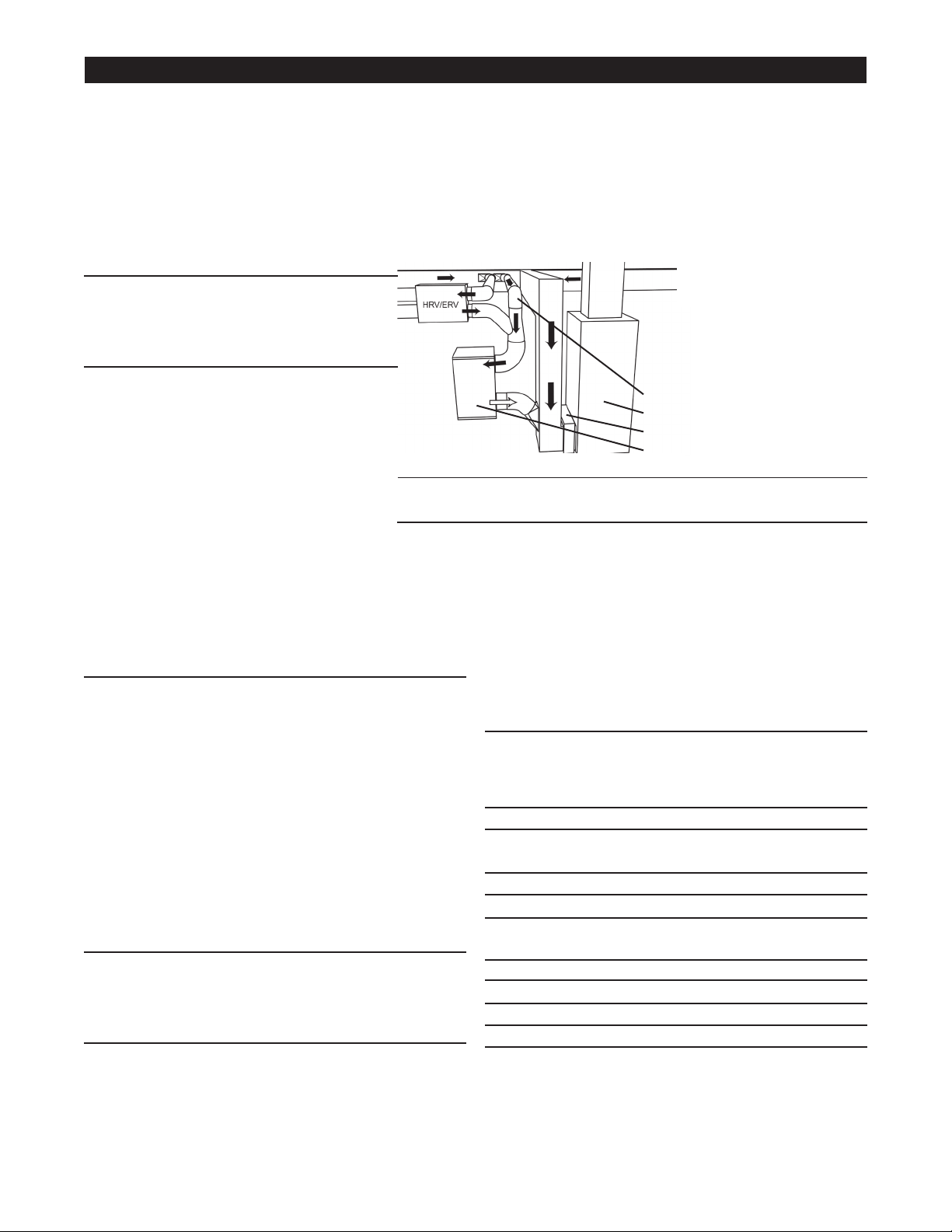
Figure 8
Forced air handler/furnace system with an HRV/ERV:
This application provides filtration of all Outdoor Air (OA) that is brought into the home through the HRV/ERV, thus
reducing the introduction of dust, pollen and mold from the outdoor air. For systems that have HRV/ERV units
LQVWDOOHGZHUHFRPPHQGGXFWLQJWKHµIUHVKDLU¶RXWIORZIURPWKH+59(59LQWRWKH+(3$V\VWHP,IWKH+59
ERV cfm (cubic feet per minute) rating is lower than that of the HEPA system, an additional return needs to be
installed into the HEPA system (See figure 8.) The outflow air from the HEPA system then needs to be installed
into the main return of the air handler/furnace system. Ensure that you follow the proper installation instructions
as outlined in the HRV/ERV installation manual(s).
Dealer Installation Instructions
Example of Return to
Return Installation with
an HRV/ERV
For homes with a forced
air handler/furnace system
and an HRV/ERV system.
Additional Return
Air Handler/Furnace
Air Handler/Furnace Filter
HEPA System
NOTE: This filtration system is an ADDITIONAL filter, and does
NOT replace the existing air handler/furnace system filter.
7
AirWash Whisper Manual 2019_1
Independent Operation:
The HEPA system can be used independently of any other equipment! The intake and outflow of the filtration
system can be ducted into the same room to create a cleaner environment almost anywhere. The intake or outflow
can also be ducted elsewhere. The intake and outflow should be installed on opposite sides of the room; however,
this varies according to your specific needs.
Preparation:
Here are some things to consider as you
decide where to install the HEPA system
independently of other systems.
Location:
• Make sure there is room to open the
HEPA filter access panel for filter
changes/inspections.
• Keep the HEPA system away from
possible water damage.
• Vibration pads will reduce vibration for
installations where the unit is placed on
the floor.
• Install HEPA system on floor
or suspended platform. If the unit
is suspended, screws must not
penetrate through the cabinet. Make
sure that you have the proper chains/straps/joists and
equipment to keep unit secure.
Intake0DUNHGDVµ$LU,Q¶RQXQLW
• Intake ducts should be installed near the floor for
optimum airflow. If space does not allow, then the inlet
can be installed in the ceiling.
• Intake duct should be installed at least 6 ft. away from
the outflow duct.
• Intake duct should be installed at opposite end of the
room from the outflow duct(s) if in the same room.
• Diffusers are recommended to help distribute airflow
evenly.
Outflow0DUNHGDVµ&OHDQ$LU2XW¶RQXQLW
• Outflow(s) should be installed in the ceiling away from
any other air inlet(s).
• Room diffusers are recommended to help distribute
airflow evenly in the occupied space.
Ducting:
,I+(3$V\VWHPLVLQVWDOOHGZKHUHLQOHWDQGRXWÀRZ
collars face down, metal elbows must be connected to
ERWKLQOHWDQGRXWÀRZFROODUV
• Each connection must be sealed with aluminum tape or
mastic, including all vent connections.
• Installed duct runs should be as straight as possible (if
the duct runs are too long, reduced CFM may result).
,IGXFWLVH[SRVHGWRXQFRQGLWLRQHGDLULQVXODWHGÀH[
duct is highly recommended.
([WHUQDOO\LQVXODWHGÀH[GXFWFDQDOVREHXVHGIRUQRLVH
reduction purposes.
• For best indoor air quality, do not use ductboard or
¿EHUJODVVLQVLGHRIGXFWV
Electricity:
• The unit must be plugged into a grounded 120V, 60Hz.
outlet.
Required Materials for Installation of Unit:
Items for AWW-350
Flex or rigid duct 8” round & 6” round
(length as required)
Takeoffs One 8” & One 6”
Diffusers One 8” & One 6”
Items for AWW-675
Flex or rigid duct 10” round & 8” round
(length as required)
Takeoffs One 10” & One 8”
Diffusers One 10” & One 8”
All Models
Aluminum tape or mastic as required
0LVFKDQJLQJPDWHULDOV¿HOGSURYLGHG
NOTE: Be sure to review ‘Rules for Safe Installation and
Operation’ on page 1 of this document
before start-up of this unit.
Dealer Installation Instructions
Example of Single Room Stand Alone System Installation
For single rooms where increased filtration is desired such as a
dedicated “smoking room”.
Air should be drawn from
location B if space is
available, otherwise use
location A.
Figure 9
A
B
HEPA System
8
AirWash Whisper Manual 2019_1
Operation
Maintenance
1. Make sure that the unit is plugged into a grounded outflow (120 Volt, 60 Hz).
2. For optimum performance, the HEPA system should operate when the indoor air handler/furnace blower is
on.
7XUQWKHXQLWRQE\SUHVVLQJWKHRQRIIVZLWFKWRWKHµ¶SRVLWLRQ7KHVZLWFKVKRXOGOLJKWXSZKHQWKHXQLWLV
on.
7RWXUQWKHXQLWRIISUHVVWKHRQRIIVZLWFKWRWKHµ¶SRVLWLRQ7KHVZLWFKOLJKWVKRXOGWXUQRIIZKHQWKHXQLWLV
off.
Proper care and maintenance of your HEPA
system will ensure years of service. The unit must
be turned off during service/maintenance or when
filters are being changed.
It is recommended that gloves and a filtered
breathing mask be worn during filter replacement.
Filter Change Schedule
Note: Failure to properly maintain your HEPA
system will decrease the efficiency and air flow.
Foam Pre-Filter: 3 to 4 months*
HEPA Filter: 2 to 5 years
Inner Carbon Filter: 6 months
Optional Carbon Canister: 12 months
* The foam pre-filters can be washed and reused
NOTE: Filter life is based on average air content.
Some filters may need to be changed more
often due to higher amounts of dust, humidity, or
chemicals found in your ambient air. Additionally,
people who are more sensitive to these airborne
contaminants may desire more frequent filter
changes.
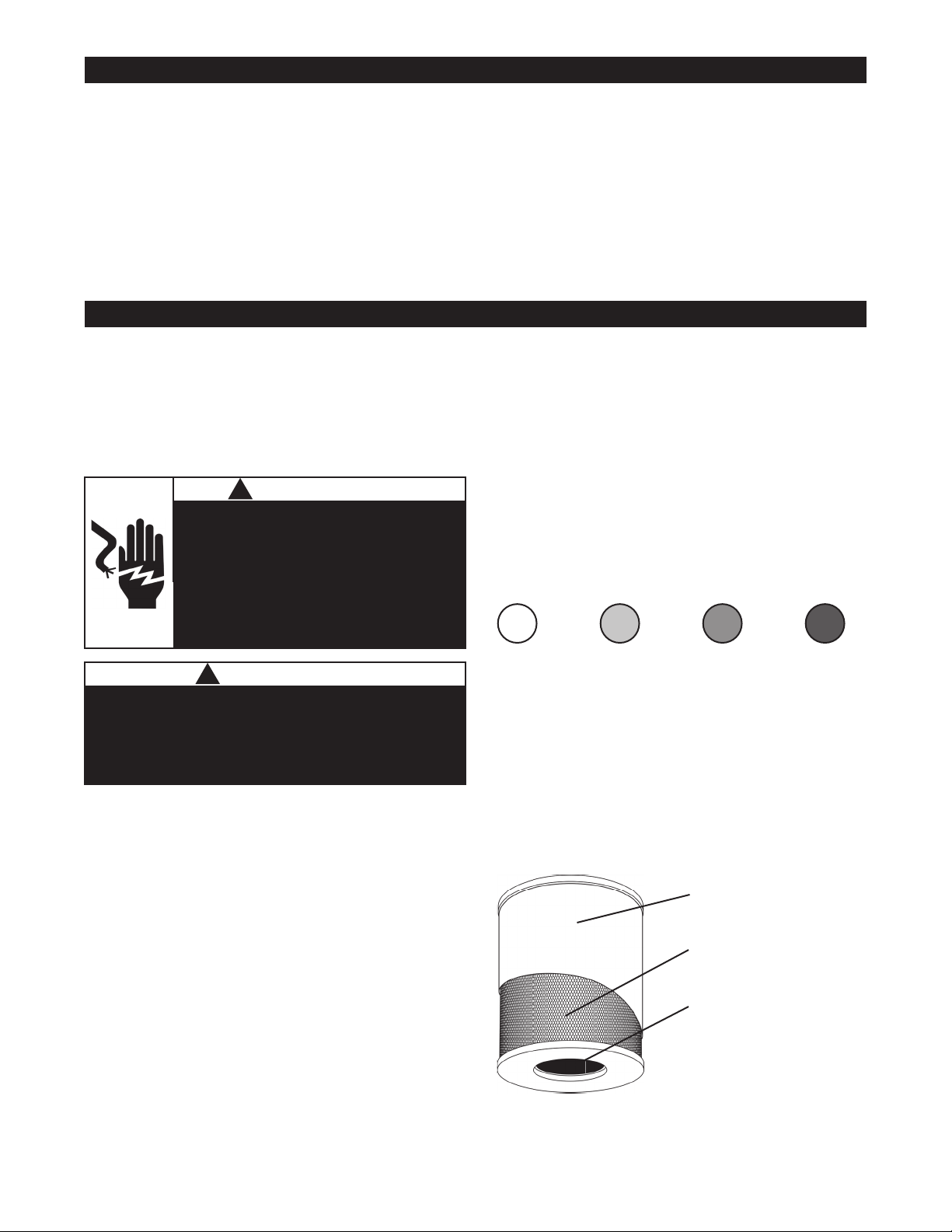
Filter Changing Guidelines
Pre-Filter:
Dust and other large particles will collect on the pre-
¿OWHURYHUWLPH7KHFRORURIWKH¿OWHUZLOOFKDQJHDV
SDUWLFXODWHVEXLOGXSRQWKHSUH¿OWHU&KDQJHWKH
SUH¿OWHUZKHQ\RXFDQVHHWKHSDUWLFXODWHEXLOGXS
VWDUWWRFORJXSWKHSUH¿OWHU
HEPA Filter:
$V WKH +(3$ ¿OWHU FDSWXUHV SDUWLFXODWHV LW ZLOO
GDUNHQRYHUWLPH5HSODFHWKH+(3$¿OWHUZKHQLW
darkens to the level seen in example D.
Inner Carbon Filter:
7KHLQQHUFDUERQ¿OWHUZLOOUDUHO\ORRNXVHG7KLV
¿OWHU FDSWXUHV RGRUV DQG JDVVHV \HW WKH ¿OWHU¶V
DSSHDUDQFHZLOOQRWFKDQJH:KHQWKLV¿OWHUKDV
reached its maximum adsorbancy of odors and
JDVHV LW ZLOO QR ORQJHU ZRUN 5HSODFH WKLV ¿OWHU
when it no longer seems to capture odors, or every
3 months (12 months for optional Carbon Canister),
ZKLFKHYHURFFXUV¿UVW
A. New B. Used C. Used D. Replace
Risk of Sharp Edges Hazard.
Equipment sharp edges can cause injuries.
Avoid grasping equipment edges without protective
gloves.
!
CAUTION
Electrical Shock Hazard.
Can cause injury or death.
Disconnect all electrical power supplies
before servicing.
Do not operate equipment without
access panels in place.
!
WARNING
Pre-Filter
HEPA Filter
Inner Carbon Filter
Figure 10
9
AirWash Whisper Manual 2019_1
Dealer Filter Change Instructions
It is recommended that gloves and a filtered
breathing mask be worn during filter replacement
to avoid breathing particulates (dust, mold, pollen,
etc.) captured on the filter that become airborne
during the filter(s) change.
The old filters should be wrapped and sealed in
plastic bags immediately upon removal from the
unit, to avoid distributing particles throughout the
house during the process of disposal.
1. Accessing the filters
a. Remove safety screw(s) from HEPA filter access
panel.
b. Unlatch the two retaining clips and lift off HEPA filter
access panel.
c. Bracing the unit so it does not move, turn the HEPA
cartridge counter-clockwise and lift/pull out.
2. Pre-filter Replacement
a. Pull the pre-filter up and off the unit. NOTE: The
pre-fiter may contain contaminants. Remove it slowly
to avoid releasing particles back into the air.
b. Foam pre-filters can be washed several times.
Wash by hand in warm water. Let dry completely
before placing back onto the HEPA cartridge.
b. If replacing the filter, remove plastic
shrink wrap from the new pre-filter.
c. Stretch the new/washed filter around the top of
the HEPA cartridge and slide it down into place.
3. Inner Carbon Filter Replacement
a. Look inside the HEPA cartridge to locate the two
ends of the inner carbon filter.
b. Pull one end of the old inner carbon filter in and
bend it into a loose roll so it can be removed.
c. Remove the inner carbon filter from the HEPA
cartridge.
d. Remove plastic shrink wrap from the new inner
carbon filter.
e. Unroll the inner carbon filter and roll it up in the
opposite direction (this makes the filter follow a
more contoured profile against the inner HEPA filter
surfaces and helps keep it in place), place the rolled
inner carbon filter inside the HEPA cartridge and
JHQWO\XQUROOLWXQWLOWKHHQGVµEXWW¶WRJHWKHUDQGWKH
filter is snug against the HEPA filter.
4. HEPA Filter Replacement
D ,IUHSODFLQJWKH+(3$¿OWHUZLWKDQHZ¿OWHUGLVFDUG
ROG +(3$ ¿OWHU DQG XVH QHZ ZKHQ UHSODFLQJ WKH
+(3$¿OWHULQWRWKHXQLW
E :LWKHDFKDQQXDO¿OWHUUHSODFHPHQWNLWDQHZµR¶ULQJ
is provided. The old one is removed by pinching it
EHWZHHQWZR¿QJHUVDQGSXOOLQJLWRIIWKHFROODURQ
the blower deck.
F 'LVFDUGROGµR¶ULQJ
G 3ODFH WKH QHZ µR¶ ULQJ RQWR WKH FROODU DQG VOLGH LW
down to the base of the blower deck.
5. Optional Carbon Canister
a. Remove old carbon canister (if installed) by pulling
LWRXWIURPWKHLQVLGHRIWKH+(3$¿OWHU
E ,I UHSODFLQJ DQ LQQHU FDUERQ ¿OWHU ZLWK WKH FDUERQ
FDQLVWHUUHPRYHLQQHUFDUERQ¿OWHUE\IROORZLQJWKH
steps a. to c. in section 3.
c. Remove the plastic shrink wrap from the new carbon
canister.
d. Slide the carbon canister into the HEPA cartridge,
VPDOOHUHQG¿UVW7KHFDUERQFDQLVWHUVKRXOGVOLGH
all the way in until the metal edges at the base meet
WKH+(3$¿OWHU
H 6XSSRUW WKH FDUERQ FDQLVWHU ZLWK \RXU ¿QJHUV VR
it does not slide out when replacing the HEPA
cartridge assembly into the unit.
6 . Installing the HEPA Filter Cartridge
D :LWK WKH ¿OWHUV FKDQJHG RU LQVSHFWHG DOO ¿OWHUV
are ready to be placed back into the unit. Place
the HEPA cartridge gently into the unit (if a carbon
canister is being used, take care not to let it slide out
as it is heavy and could damage the unit).
b. When the HEPA cartridge is in place, brace the unit,
press down and gently turn it clockwise to lock it into
place. If too much force is used, the cartridge may
EHGLI¿FXOWWRUHPRYH
F 5HSODFH WKH +(3$ ¿OWHU DFFHVV SDQHO DQG ODWFK LW
with the two retaining clips.
G 5HLQVWDOO VDIHW\ VFUHZV LQWR +(3$ ¿OWHU DFFHVV
panel.
H 3OXJWKHXQLWEDFNLQWRDSRZHURXWÀRZDQGWXUQLW
on.
Risk of Sharp Edges Hazard.
Equipment sharp edges can cause injuries.
Avoid grasping equipment edges without protective
gloves.
!
CAUTION
Electrical Shock Hazard.
Can cause injury or death.
Disconnect all electrical power supplies
before servicing.
Do not operate equipment without ac-
cess panels in place.
!
WARNING
10
AirWash Whisper Manual 2019_1
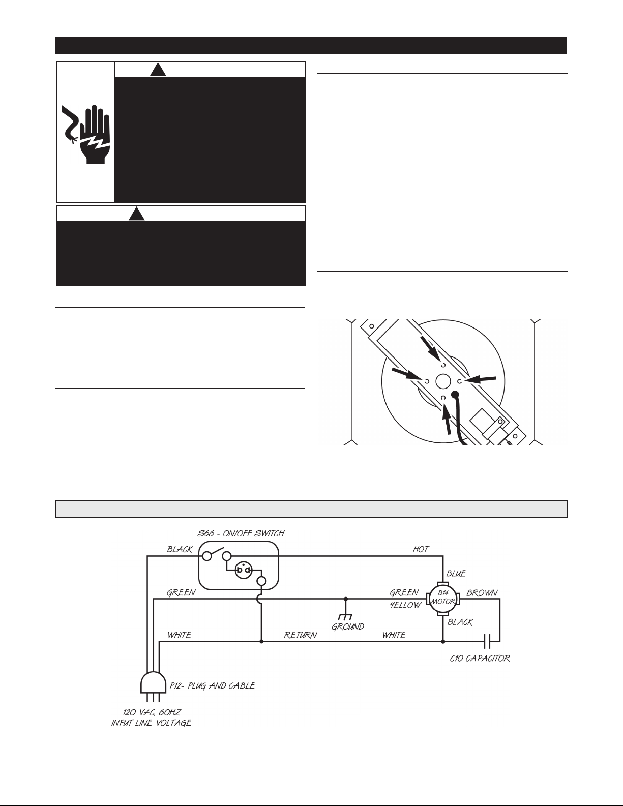
1. Accessing the motor assembly
a. Turn the unit off and unplug it from any electrical
source before opening the cabinet.
b. Remove the safety screw(s) from the motor section
access panel.
c. Lift the door off the unit.
2. Removing the old motor assembly
a. Disconnect all four motor wires from switch, ground
post and capacitor.
b. Disconnect the two white wires from the capacitor.
c. Separate the motor from the motor mount by
removing the four screws found in Figure 11.
d. Slide the motor out from under the motor mount to
remove it from the unit.
3. Installing the new motor assembly
a. Slide the new motor into the motor mount, making
sure that the wires go through the smaller hole
offset from the center of the bracket.
b. Secure the new motor to the motor mount with the
four screws removed in step 2c.
d. Connect the wires as follows:
- Blue wire from motor to the on/off switch.
- Yellow/green wire from motor to the ground post.
- Brown wire from the motor to a capacitor post.
- Black wire from the motor to the other capacitor
post.
- White wire from the on/off switch to the
capacitor via the black wire piggyback post.
- White wire from the power cord to the
FDSDFLWRUYLDWKHRWKHUZKLWHZLUH¶VSLJJ\EDFNSRVW
4. Closing the unit
a. Replace the motor section access panel and secure
it with the eight screws removed in step 1b.
b. Plug the unit into its electrical source and turn it on.
Dealer Motor Assembly Replacement Instructions
Electrical Diagram
Risk of Sharp Edges Hazard.
Equipment sharp edges can cause injuries.
Avoid grasping equipment edges without protective
gloves.
!
CAUTION
Electrical Shock Hazard.
Can cause injury or death.
Disconnect all electrical power supplies
before servicing.
Do not operate equipment without
access panels in place.
Do not use this fan with any solid-state
speed control device.
!
WARNING
Figure 12
Figure 11
11

AirWash Whisper Manual 2019_1
Replacement Parts
Replacement Parts for AWW-350 (Qty.) Canadian U.S. International
Complete Filter Kit (1 Pre-filter, 1 HEPA, 1 Carbon) 9100443709 9101443709 9101443709
Annual Filter Kit ( 1 Pre-filter, 2 Carbon) 94004061 94014061 94014061
Motor Assembly (120V) 99001200 99011200 99011200
Motor Assembly (220V) 99002800 99012800 99012800
HEPA Filter Cartridge 90004487 90014487 90014487
Pre-Filter (Foam) 92004-31 92014-31 92014-31
Carbon Filter 93004-21 93014-21 93014-21
&DUERQ&DQLVWHU&DUERQ
&DUERQ=HROLWH&DQLVWHU&DUERQ=HROLWH
Replacement Parts for AWW-675 (Qty.) Canadian U.S. International
Complete Filter Kit (1 Pre-filter, 1 HEPA, 1 Carbon) 9100443709 9101443709 9101443709
$QQXDO)LOWHU.LW3UH¿OWHU&DUERQ
Motor Assembly (120V) 99002400 99012400 99012400
Motor Assembly (220V) 99003000 99013000 99013000
HEPA Filter Cartridge 90004487 90014487 90014487
Pre-Filter (Foam) 92004-31 92014-31 92014-31
Carbon Filter 93004-21 93014-21 92014-21
&DUERQ&DQLVWHU&DUERQ
&DUERQ=HROLWH&DQLVWHU&DUERQ=HROLWH
Use this unit only in the manner intended by the manufacturer. If you have questions, contact Hawk
Environmental at ????.
Contact your local Hawk Environmental dealer to order replacement parts.
12
rebmuN traPderiuqeR YTQ576/053 WWA rof straP tnemecalpeR
Annual Filter Kit - Standard ( 1 Pre-filter, 2 Carbon) 1 93-T-16ST00-ET
Annual Filter Kit - Plus ( 1 Pre-filter, 1 Carbon VOC) 1 93-T-16PL02-ET
TE-EM61-T-091egdirtraC retliF APEH
3M-4M02-ROM-A-981)~V032/022( 053 WWA ylbmessA rotoM
1M-5M02-ROM-A-981)~V032/022( 576 WWA ylbmessA rotoM
Use this unit only in the manner intended by the manufacturer. If you have questions, contact Hawk Environmental® at
(206) 620 0311.
Contact your local Hawk Environmental® dealer to order replacement parts.