Loading ...
Loading ...
Loading ...

9
English
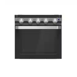
Fig. 5
Pressure Check
1. Turn LP gas off to the appliance.
2. Remove the Screw with the sealing gasket from the
pressure test port on the range. (Fig. 6)
Fig. 6
3. Using the rubber tube from the pressure check measuring
device, slide the rubber tube down over the gas pressure
test port. The rubber tube should seal around the pressure
test port on the range.
4. Turn on the LP gas to the appliance.
5. The pressure gauge tester should measure between 10”
WC to 13.8” WC. (Fig. 7)
Fig. 7
6. Turn off the LP gas to the appliance.
7. Remove the rubber tube of the pressure check measuring
device.
8. Replace the screw with the gasket from step 2. Before
replacing the screw, inspect the rubber gasket seal for any
signs of damage. Replace seal if damaged.
9. Tighten the screw to 1.3 Nm to 1.7 Nm.
NOTE: Ensure the product is gas leak checked after the
pressure check test is completed by also testing the pressure
check port screw. If any leaks are detected around the
pressure check port screw and gasket, a new one can be
purchased. Call Furrion support for a replacement.
Electrical Connection
CAUTION
PRODUCT DAMAGE HAZARD
Ɣ Connect to 12V DC service only.
Ɣ Connect only to protected circuit fused for not more
than 15 Amps.
Ɣ DO NOT hi-pot range unless electronic ignition system
has been disconnected.
Connect a positive 12V power supply wire to the range oven
black 12V light wire and a negative 12V power supply wire to
the range oven white 12V light wire. (Fig. 8)
NOTE: Ensure to connect the wires with the correct polarity.
Black is “+” and White is “-”.
Fig. 8
Wiring Diagram
+
-
12V Lamp
Switch
22# AWG
22# AWG
Diode
12V DC
Thermostate
Valve LED
Right Burner
Knob LED
Left Burner
Knob LED
Center
Burner Knob
LED
Ignition
Knob LED
Glass Cover Replacement
1. Align the top glass cover assembly tabs x 2 with the slots
on the back side of the console and place it into the top of
the range cooktop. (Fig. 9)
Fig. 9
Loading ...
Loading ...
Loading ...