Loading ...
Loading ...
Loading ...
6
WARNING
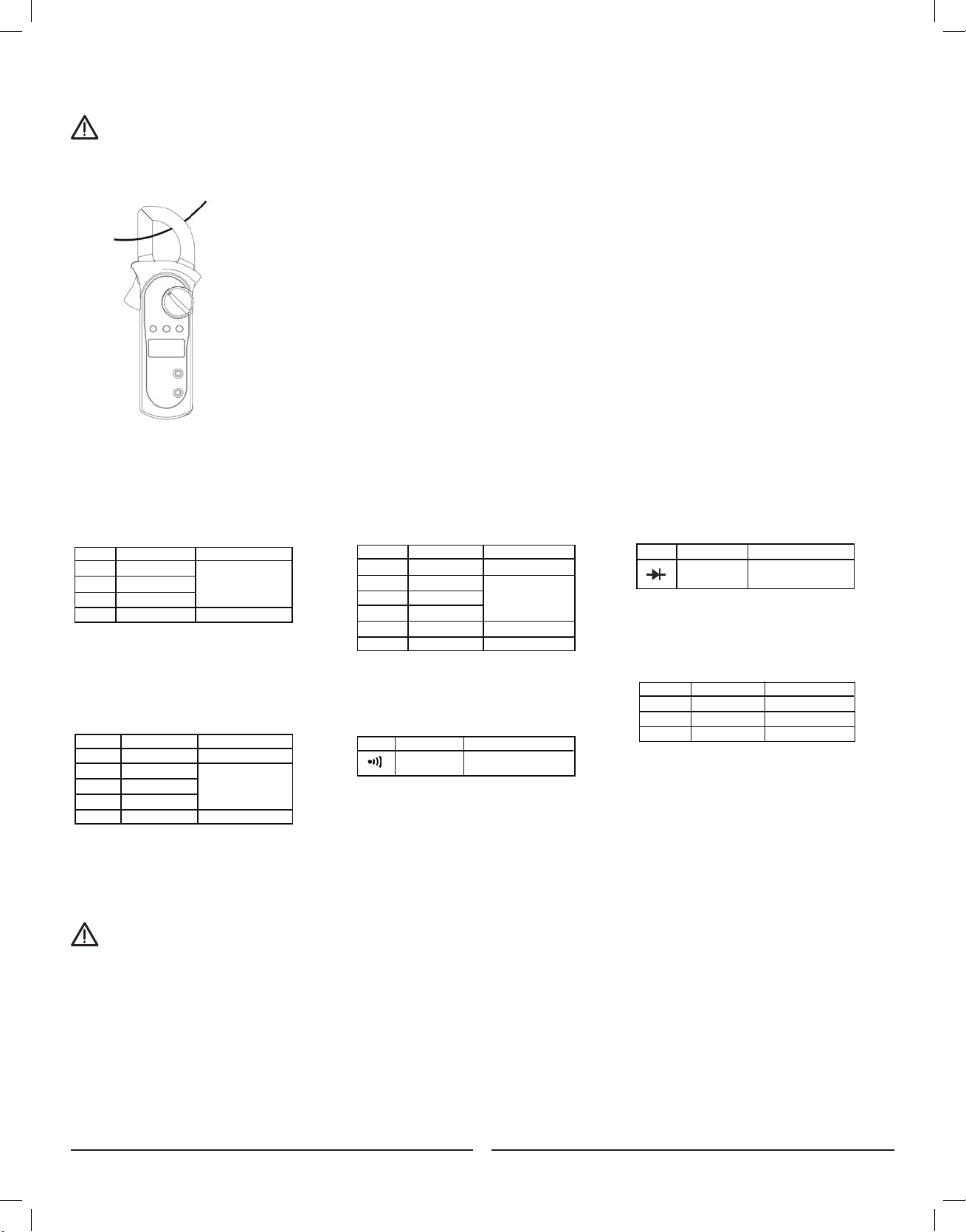
F. Measuring AC Current (See Figure 8)
To avoid electric shock, never measure current while the test leads are inserted into the input terminals and disconnect test leads and
tested circuit connections. Never attempt an in-circuit current measurement where the open-circuit voltage between the circuit and the
ground is greater than 600V. Use proper function and range for any measurements.
To measure current, do the following:
1. Set the rotary switch to 20A~, 200 A~ or 600 A~
2. Press the trigger to open the transformer jaws.
3. Center the conductor within the transformer jaw, then release the Meter slowly until the
transformer jaw is completely closed, Make sure the conductor to be tested is placed at the
center of the transformer jaw, otherwise it will cause deviation. The Meter can only measure one
conductor at a time, to measure more than one conductor at a time will cause deviation.
NOTE:
When current measurement has been completed,disconnect the
connection between the conductor under test and the jaw, and
remove the conductor away from the transformer jaw of the Meter.
Figure 3
Figure 2
Figure 4
Figure 5
Figure 6
Figure 7
Figure 8
Figure 9
Figure 7
VI. ACCURACY SPECIFICATIONS
Accuracy: ±(a% reading + b digits), guarantee for 1 year.
Operating temperature: 23˚C±5˚C
Relative humidity: ≤75%R.H
Temperature coefficient: 0.1×(specified accuracy) /1˚C
International Electrical Symbols
AC (Alternating Current)
DC (Direct Current)
Grounding
Double Insulated
Warning. Refer to the Operating Manual
Low Battery Indication
Continuity Test
Diode
Conforms to Standards of European Union
Number
Description
1 Indicator for AC voltage or current
2 Indicator for DC voltage
3 The battery is low.
Warning: To avoid false readings, which
could lead to possible electric shock or
personal injury, replace the battery as soon as
the battery indicator appears.
4 The Meter is in the auto range mode in
which the Meter automatically selects
the range with the best resolution.
5 Test of diode
6 The continuity buzzer is on
7 Maximum reading displayed
8 Data hold is active
9 Amperes (amps). The unit of current.
10 Ω: Ohm. The unit of resistance.
kΩ:Kilohm. 1000 ohms
MΩ:Megohm. 1,000,000 ohms
11 V: Volts. The unit of voltage.
mV: Millivolt. 0.001 volts
12 Indicates negative reading
Rotary Functional Buttons
Switch SELECT MAX HOLD
Positions
Ω • N/A •
N/A • •
N/A • •
A 20A N/A • •
A 200A N/A • •
A 600A N/A • •
A. AC Voltage: Auto Ranging
Range
Resolution Accuracy
2.000V
1mV
20.00V
10mV ±(1.2%+5)
200.0V
100mV
600V
1V ±(1.5%+5)
B. DC Voltage: Auto Ranging
Range Resolution Accuracy
200.0mV 0.1mV ±(0.8%+3)
2.000V 1mV
20.00V 10mV ±(0.8%+1)
200.0V 100mV
600V 1V ±(1%+3)
Remarks:
● Input impedance: 10MΩ
● Overload protection: 600V rms
C. Resistance: Auto Ranging
Range Resolution Accuracy
200.0Ω 100mΩ ±(1.2%+2)
2.000kΩ 1Ω
20.00kΩ 10Ω ±(1%+2)
200.0kΩ 100Ω
2.000MΩ 1kΩ ±(1.2%+2)
20.00MΩ 10kΩ ±(1.5%+2)
Remark:
● Overload protection: 600Vp
D. Continuity
Range Resolution Accuracy
Around <10Ω,the
buzzer beeps.
Remark:
● Overload Protection: 600Vp
● Open circuit voltage approximate 0.45V.
● The buzzer may or may not beeps when the
resistance of a circuit under test is more
than 10Ω.
E. Diode
Range Resolution Accuracy
Display approximate
forward voltage drop
Remarks:
● Overload Protection: 600Vp
● Open circuit voltage approximate 1.48V.
1mV
100mΩ
F. AC Current: Auto Ranging
Range Resolution Accuracy
20.00A 0.01A ±(2.0%+5)
200.0A 0.1A ±(1.5%+5)
600A 1A ±(2.0%+8)
Remarks:
Remarks:
• Overload protection:600V rms
• Input impedance: 10MΩ // <100pF
• Displays RMS value of sine wave
(mean value response).
• Frequency response: 40Hz~400Hz.
International Electrical Symbols
AC (Alternating Current)
DC (Direct Current)
Grounding
Double Insulated
Warning. Refer to the Operating Manual
Low Battery Indication
Continuity Test
Diode
Conforms to Standards of European Union
Number
Description
1 Indicator for AC voltage or current
2 Indicator for DC voltage
3 The battery is low.
Warning: To avoid false readings, which
could lead to possible electric shock or
personal injury, replace the battery as soon as
the battery indicator appears.
4 The Meter is in the auto range mode in
which the Meter automatically selects
the range with the best resolution.
5 Test of diode
6 The continuity buzzer is on
7 Maximum reading displayed
8 Data hold is active
9 Amperes (amps). The unit of current.
10 Ω: Ohm. The unit of resistance.
kΩ:Kilohm. 1000 ohms
MΩ:Megohm. 1,000,000 ohms
11 V: Volts. The unit of voltage.
mV: Millivolt. 0.001 volts
12 Indicates negative reading
Rotary Functional Buttons
Switch SELECT MAX HOLD
Positions
Ω • N/A •
N/A • •
N/A • •
A 20A N/A • •
A 200A N/A • •
A 600A N/A • •
A. AC Voltage: Auto Ranging
Range Resolution Accuracy
2.000V 1mV
20.00V 10mV ±(1.2%+5)
200.0V 100mV
600V 1V ±(1.5%+5)
B. DC Voltage: Auto Ranging
Range
Resolution Accuracy
200.0mV
0.1mV ±(0.8%+3)
2.000V
1mV
20.00V
10mV ±(0.8%+1)
200.0V
100mV
600V
1V ±(1%+3)
Remarks:
● Input impedance: 10MΩ
● Overload protection: 600V rms
C. Resistance: Auto Ranging
Range Resolution Accuracy
200.0Ω 100mΩ ±(1.2%+2)
2.000kΩ 1Ω
20.00kΩ 10Ω ±(1%+2)
200.0kΩ 100Ω
2.000MΩ 1kΩ ±(1.2%+2)
20.00MΩ 10kΩ ±(1.5%+2)
Remark:
● Overload protection: 600Vp
D. Continuity
Range Resolution Accuracy
Around <10Ω,the
buzzer beeps.
Remark:
● Overload Protection: 600Vp
● Open circuit voltage approximate 0.45V.
● The buzzer may or may not beeps when the
resistance of a circuit under test is more
than 10Ω.
E. Diode
Range Resolution Accuracy
Display approximate
forward voltage drop
Remarks:
● Overload Protection: 600Vp
● Open circuit voltage approximate 1.48V.
1mV
100mΩ
F. AC Current: Auto Ranging
Range Resolution Accuracy
20.00A 0.01A ±(2.0%+5)
200.0A 0.1A ±(1.5%+5)
600A 1A ±(2.0%+8)
Remarks:
Remarks:
• Input impedance: 10MΩ
• Overload protection: 600V rms
Remarks:
• Overload protection: 600Vp
International Electrical Symbols
AC (Alternating Current)
DC (Direct Current)
Grounding
Double Insulated
Warning. Refer to the Operating Manual
Low Battery Indication
Continuity Test
Diode
Conforms to Standards of European Union
Number
Description
1 Indicator for AC voltage or current
2 Indicator for DC voltage
3 The battery is low.
Warning: To avoid false readings, which
could lead to possible electric shock or
personal injury, replace the battery as soon as
the battery indicator appears.
4 The Meter is in the auto range mode in
which the Meter automatically selects
the range with the best resolution.
5 Test of diode
6 The continuity buzzer is on
7 Maximum reading displayed
8 Data hold is active
9 Amperes (amps). The unit of current.
10 Ω: Ohm. The unit of resistance.
kΩ:Kilohm. 1000 ohms
MΩ:Megohm. 1,000,000 ohms
11 V: Volts. The unit of voltage.
mV: Millivolt. 0.001 volts
12 Indicates negative reading
Rotary Functional Buttons
Switch SELECT MAX HOLD
Positions
Ω • N/A •
N/A • •
N/A • •
A 20A N/A • •
A 200A N/A • •
A 600A N/A • •
A. AC Voltage: Auto Ranging
Range Resolution Accuracy
2.000V 1mV
20.00V 10mV ±(1.2%+5)
200.0V 100mV
600V 1V ±(1.5%+5)
B. DC Voltage: Auto Ranging
Range Resolution Accuracy
200.0mV 0.1mV ±(0.8%+3)
2.000V 1mV
20.00V 10mV ±(0.8%+1)
200.0V 100mV
600V 1V ±(1%+3)
Remarks:
● Input impedance: 10MΩ
● Overload protection: 600V rms
C. Resistance: Auto Ranging
Range
Resolution Accuracy
200.0Ω 100mΩ
±(1.2%+2)
2.000kΩ
1Ω
20.00kΩ
10Ω ±(1%+2)
200.0kΩ
100Ω
2.000MΩ
1kΩ ±(1.2%+2)
20.00MΩ
10kΩ ±(1.5%+2)
Remark:
● Overload protection: 600Vp
D. Continuity
Range Resolution Accuracy
Around <10Ω,the
buzzer beeps.
Remark:
● Overload Protection: 600Vp
● Open circuit voltage approximate 0.45V.
● The buzzer may or may not beeps when the
resistance of a circuit under test is more
than 10Ω.
E. Diode
Range Resolution Accuracy
Display approximate
forward voltage drop
Remarks:
● Overload Protection: 600Vp
● Open circuit voltage approximate 1.48V.
1mV
100mΩ
F. AC Current: Auto Ranging
Range Resolution Accuracy
20.00A 0.01A ±(2.0%+5)
200.0A 0.1A ±(1.5%+5)
600A 1A ±(2.0%+8)
Remarks:
Remarks:
• Overload Protection: 600Vp
• Open circuit voltage approximate 0.45V.
• The buzzer may or may not beeps when
the resistance of a circuit under test is
more than 10Ω.
International Electrical Symbols
AC (Alternating Current)
DC (Direct Current)
Grounding
Double Insulated
Warning. Refer to the Operating Manual
Low Battery Indication
Continuity Test
Diode
Conforms to Standards of European Union
Number
Description
1 Indicator for AC voltage or current
2 Indicator for DC voltage
3 The battery is low.
Warning: To avoid false readings, which
could lead to possible electric shock or
personal injury, replace the battery as soon as
the battery indicator appears.
4 The Meter is in the auto range mode in
which the Meter automatically selects
the range with the best resolution.
5 Test of diode
6 The continuity buzzer is on
7 Maximum reading displayed
8 Data hold is active
9 Amperes (amps). The unit of current.
10 Ω: Ohm. The unit of resistance.
kΩ:Kilohm. 1000 ohms
MΩ:Megohm. 1,000,000 ohms
11 V: Volts. The unit of voltage.
mV: Millivolt. 0.001 volts
12 Indicates negative reading
Rotary Functional Buttons
Switch SELECT MAX HOLD
Positions
Ω • N/A •
N/A • •
N/A • •
A 20A N/A • •
A 200A N/A • •
A 600A N/A • •
A. AC Voltage: Auto Ranging
Range Resolution Accuracy
2.000V 1mV
20.00V 10mV ±(1.2%+5)
200.0V 100mV
600V 1V ±(1.5%+5)
B. DC Voltage: Auto Ranging
Range Resolution Accuracy
200.0mV 0.1mV ±(0.8%+3)
2.000V 1mV
20.00V 10mV ±(0.8%+1)
200.0V 100mV
600V 1V ±(1%+3)
Remarks:
● Input impedance: 10MΩ
● Overload protection: 600V rms
C. Resistance: Auto Ranging
Range Resolution Accuracy
200.0Ω 100mΩ ±(1.2%+2)
2.000kΩ 1Ω
20.00kΩ 10Ω ±(1%+2)
200.0kΩ 100Ω
2.000MΩ 1kΩ ±(1.2%+2)
20.00MΩ 10kΩ ±(1.5%+2)
Remark:
● Overload protection: 600Vp
D. Continuity
Range Resolution
Accuracy
Around <10Ω,the
buzzer beeps.
Remark:
● Overload Protection: 600Vp
● Open circuit voltage approximate 0.45V.
● The buzzer may or may not beeps when the
resistance of a circuit under test is more
than 10Ω.
E. Diode
Range Resolution Accuracy
Display approximate
forward voltage drop
Remarks:
● Overload Protection: 600Vp
● Open circuit voltage approximate 1.48V.
1mV
100mΩ
F. AC Current: Auto Ranging
Range Resolution Accuracy
20.00A 0.01A ±(2.0%+5)
200.0A 0.1A ±(1.5%+5)
600A 1A ±(2.0%+8)
Remarks:
Remarks:
• Overload Protection: 600Vp
• Open circuit voltage approximate 1.48V.
International Electrical Symbols
AC (Alternating Current)
DC (Direct Current)
Grounding
Double Insulated
Warning. Refer to the Operating Manual
Low Battery Indication
Continuity Test
Diode
Conforms to Standards of European Union
Number
Description
1 Indicator for AC voltage or current
2 Indicator for DC voltage
3 The battery is low.
Warning: To avoid false readings, which
could lead to possible electric shock or
personal injury, replace the battery as soon as
the battery indicator appears.
4 The Meter is in the auto range mode in
which the Meter automatically selects
the range with the best resolution.
5 Test of diode
6 The continuity buzzer is on
7 Maximum reading displayed
8 Data hold is active
9 Amperes (amps). The unit of current.
10 Ω: Ohm. The unit of resistance.
kΩ:Kilohm. 1000 ohms
MΩ:Megohm. 1,000,000 ohms
11 V: Volts. The unit of voltage.
mV: Millivolt. 0.001 volts
12 Indicates negative reading
Rotary Functional Buttons
Switch SELECT MAX HOLD
Positions
Ω • N/A •
N/A • •
N/A • •
A 20A N/A • •
A 200A N/A • •
A 600A N/A • •
A. AC Voltage: Auto Ranging
Range Resolution Accuracy
2.000V 1mV
20.00V 10mV ±(1.2%+5)
200.0V 100mV
600V 1V ±(1.5%+5)
B. DC Voltage: Auto Ranging
Range Resolution Accuracy
200.0mV 0.1mV ±(0.8%+3)
2.000V 1mV
20.00V 10mV ±(0.8%+1)
200.0V 100mV
600V 1V ±(1%+3)
Remarks:
● Input impedance: 10MΩ
● Overload protection: 600V rms
C. Resistance: Auto Ranging
Range Resolution Accuracy
200.0Ω 100mΩ ±(1.2%+2)
2.000kΩ 1Ω
20.00kΩ 10Ω ±(1%+2)
200.0kΩ 100Ω
2.000MΩ 1kΩ ±(1.2%+2)
20.00MΩ 10kΩ ±(1.5%+2)
Remark:
● Overload protection: 600Vp
D. Continuity
Range Resolution Accuracy
Around <10Ω,the
buzzer beeps.
Remark:
● Overload Protection: 600Vp
● Open circuit voltage approximate 0.45V.
● The buzzer may or may not beeps when the
resistance of a circuit under test is more
than 10Ω.
E. Diode
Range Resolution Accuracy
Display approximate
forward voltage drop
Remarks:
● Overload Protection: 600Vp
● Open circuit voltage approximate 1.48V.
1mV
100mΩ
F. AC Current: Auto Ranging
Range Resolution Accuracy
20.00A 0.01A ±(2.0%+5)
200.0A 0.1A ±(1.5%+5)
600A 1A ±(2.0%+8)
Remarks:
Remarks:
• Overload protection: 600A rms
• Frequency Response: 50Hz~60Hz
• Displays RMS value of sine wave
(mean value response).
• To adjust reading in accordance
with RMS value.
International Electrical Symbols
AC (Alternating Current)
DC (Direct Current)
Grounding
Double Insulated
Warning. Refer to the Operating Manual
Low Battery Indication
Continuity Test
Diode
Conforms to Standards of European Union
Number
Description
1 Indicator for AC voltage or current
2 Indicator for DC voltage
3 The battery is low.
Warning: To avoid false readings, which
could lead to possible electric shock or
personal injury, replace the battery as soon as
the battery indicator appears.
4 The Meter is in the auto range mode in
which the Meter automatically selects
the range with the best resolution.
5 Test of diode
6 The continuity buzzer is on
7 Maximum reading displayed
8 Data hold is active
9 Amperes (amps). The unit of current.
10 Ω: Ohm. The unit of resistance.
kΩ:Kilohm. 1000 ohms
MΩ:Megohm. 1,000,000 ohms
11 V: Volts. The unit of voltage.
mV: Millivolt. 0.001 volts
12 Indicates negative reading
Rotary Functional Buttons
Switch SELECT MAX HOLD
Positions
Ω • N/A •
N/A • •
N/A • •
A 20A N/A • •
A 200A N/A • •
A 600A N/A • •
A. AC Voltage: Auto Ranging
Range Resolution Accuracy
2.000V 1mV
20.00V 10mV ±(1.2%+5)
200.0V 100mV
600V 1V ±(1.5%+5)
B. DC Voltage: Auto Ranging
Range Resolution Accuracy
200.0mV 0.1mV ±(0.8%+3)
2.000V 1mV
20.00V 10mV ±(0.8%+1)
200.0V 100mV
600V 1V ±(1%+3)
Remarks:
● Input impedance: 10MΩ
● Overload protection: 600V rms
C. Resistance: Auto Ranging
Range Resolution Accuracy
200.0Ω 100mΩ ±(1.2%+2)
2.000kΩ 1Ω
20.00kΩ 10Ω ±(1%+2)
200.0kΩ 100Ω
2.000MΩ 1kΩ ±(1.2%+2)
20.00MΩ 10kΩ ±(1.5%+2)
Remark:
● Overload protection: 600Vp
D. Continuity
Range Resolution Accuracy
Around <10Ω,the
buzzer beeps.
Remark:
● Overload Protection: 600Vp
● Open circuit voltage approximate 0.45V.
● The buzzer may or may not beeps when the
resistance of a circuit under test is more
than 10Ω.
E. Diode
Range Resolution Accuracy
Display approximate
forward voltage drop
Remarks:
● Overload Protection: 600Vp
● Open circuit voltage approximate 1.48V.
1mV
100mΩ
F. AC Current: Auto Ranging
Range Resolution Accuracy
20.00A 0.01A ±(2.0%+5)
200.0A 0.1A ±(1.5%+5)
600A 1A ±(2.0%+8)
Remarks:
WARNING
VII. MAINTENANCE
This section provides basic maintenance information including battery replacement instruction.
Do not attempt to repair or service your Meter unless you are qualified to do so and have the relevant calibration,
performance test, and service information.
To avoid electrical shock or damage to the Meter, do not get water inside the case.
A. General Service
• Periodically wipe the case with a damp cloth and mild detergent. Do not use abrasives or solvents.
• Clean the terminals with a cotton swab with mild detergent. Dirt and Moisture in the terminals can affect the readings of the Meter.
• Turn the Meter power off when it is not in use.
• Remove the battery when the unit is not in use for a long time.
• Do not use or store the Meter in a place of humidity, high temperature, explosive, inflammable or strong magnetic field.
Loading ...