Loading ...
Loading ...
Loading ...
5
WARNING
WARNING
WARNING
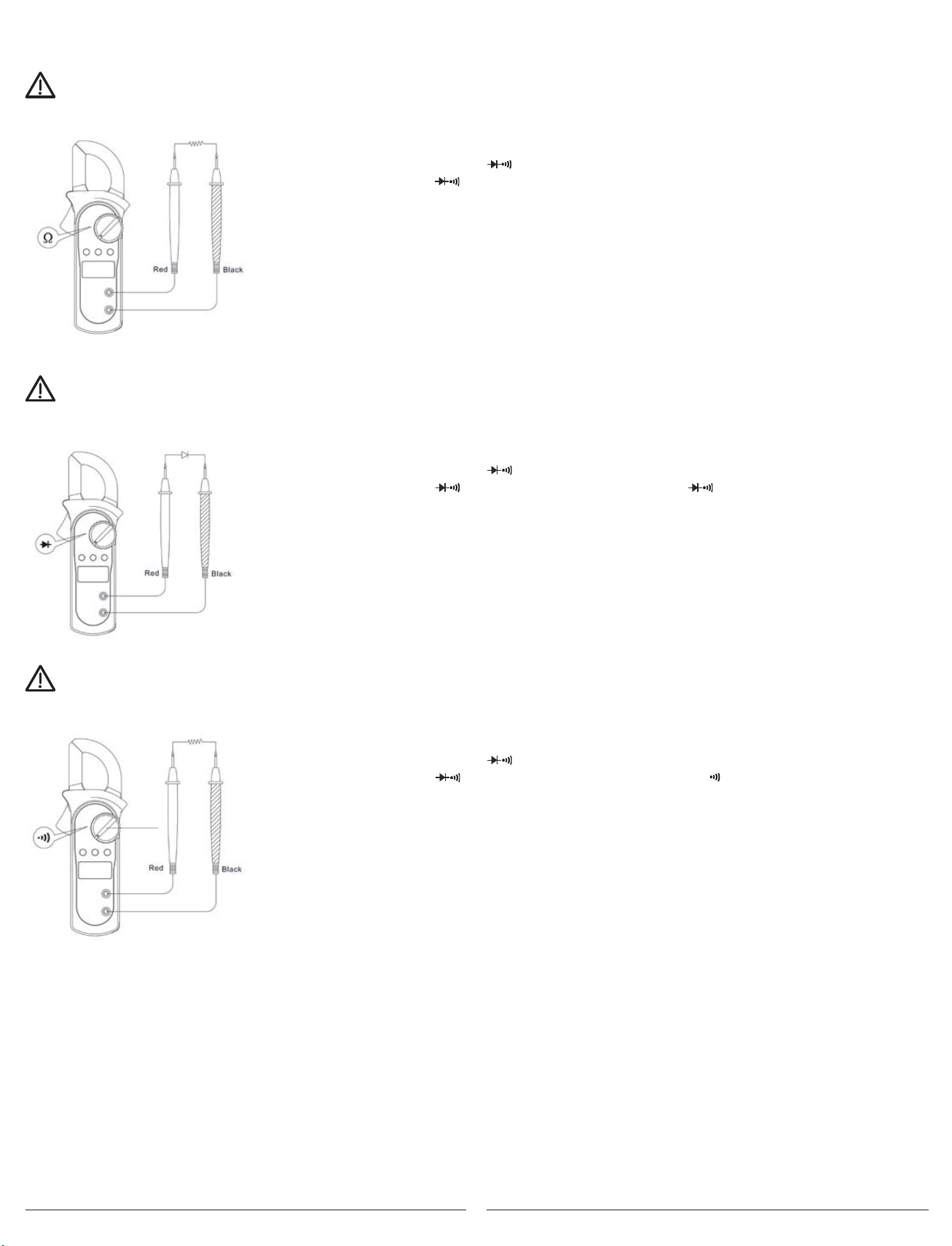
C. Measuring Resistance (See Figure 5)
To avoid damage to the Meter or to the devices under test, disconnect circuit power and discharge all the high-voltage capacitors
before measuring resistance.
To measure resistance, connect the Meter as follows:
1. Insert the red test lead into the v terminal and the black test lead into the COM terminal.
2. Set the rotary switch to ; resistance is the default or press the SELECT button to select
the Ω measurement mode.
3. Connect the test leads across with the object being measured.
The measured value shows on the display.
NOTE:
• Separating the objects being tested from the circuit when measuring
can help obtain a more accurate reading.
• When the resistance measurement has been completed, disconnect the connection
between the testing leads and the circuit under test and remove the testing leads
from the input terminals.
D. Testing Diodes (See Figure 6)
To avoid damage to the Meter or to the devices under test, disconnect circuit power and discharge all the high-voltage
capacitors before testing diodes.
To test the diode out of a circuit, connect the Meter as follows:
1. Insert the red test lead into the v terminal and the black test lead into the COM terminal.
2. Set the rotary switch to and press SELECT button to select measurement mode.
3. For forward voltage drop readings on any semiconductor component, place the red test lead
on the component’s anode and place the black test lead on the component’s cathode.
NOTE:
• Separating the objects being tested from the circuit when
measuring can help obtain a more accurate reading.
• When the diode testing has been completed, disconnect the
connection between the testing leads and the circuit under
test and remove the testing leads from the input terminals.
E. Testing for Continuity (See Figure 7)
To avoid damage to the Meter or to the devices under test, disconnect circuit power and discharge all the high-voltage capacitors
before measuring continuity.
To test for continuity, connect the Meter as follows:
1. Insert the red test lead into the v terminal and the black test lead into the COM terminal.
2. Set the rotary switch to and press the SELECT button to select measurement mode.
3. The buzzer sounds if the resistance of a circuit under test is less than 50Ω.
4. The buzzer may or may not sound if the resistance of a circuit under test is more than 50Ω.
NOTE:
When continuity testing has been completed,
disconnect the connection between the testing
leads and the circuit under test and remove
testing leads from the input terminals.
Figure 3
Figure 2
Figure 4
Figure 5
Figure 6
Figure 7
Figure 8
Figure 9
Figure 7
Figure 3
Figure 2
Figure 4
Figure 5
Figure 6
Figure 7
Figure 8
Figure 9
Figure 7
Figure 3
Figure 2
Figure 4
Figure 5
Figure 6
Figure 7
Figure 8
Figure 9
Figure 7
International Electrical Symbols
AC (Alternating Current)
DC (Direct Current)
Grounding
Double Insulated
Warning. Refer to the Operating Manual
Low Battery Indication
Continuity Test
Diode
Conforms to Standards of European Union
Number
Description
1 Indicator for AC voltage or current
2 Indicator for DC voltage
3 The battery is low.
Warning: To avoid false readings, which
could lead to possible electric shock or
personal injury, replace the battery as soon as
the battery indicator appears.
4 The Meter is in the auto range mode in
which the Meter automatically selects
the range with the best resolution.
5 Test of diode
6 The continuity buzzer is on
7 Maximum reading displayed
8 Data hold is active
9 Amperes (amps). The unit of current.
10 Ω: Ohm. The unit of resistance.
kΩ:Kilohm. 1000 ohms
MΩ:Megohm. 1,000,000 ohms
11 V: Volts. The unit of voltage.
mV: Millivolt. 0.001 volts
12 Indicates negative reading
Rotary Functional Buttons
Switch SELECT MAX HOLD
Positions
Ω • N/A •
N/A • •
N/A • •
A 20A N/A • •
A 200A N/A • •
A 600A N/A • •
A. AC Voltage: Auto Ranging
Range Resolution Accuracy
2.000V 1mV
20.00V 10mV ±(1.2%+5)
200.0V 100mV
600V 1V ±(1.5%+5)
B. DC Voltage: Auto Ranging
Range Resolution Accuracy
200.0mV 0.1mV ±(0.8%+3)
2.000V 1mV
20.00V 10mV ±(0.8%+1)
200.0V 100mV
600V 1V ±(1%+3)
Remarks:
● Input impedance: 10MΩ
● Overload protection: 600V rms
C. Resistance: Auto Ranging
Range Resolution Accuracy
200.0Ω 100mΩ ±(1.2%+2)
2.000kΩ 1Ω
20.00kΩ 10Ω ±(1%+2)
200.0kΩ 100Ω
2.000MΩ 1kΩ ±(1.2%+2)
20.00MΩ 10kΩ ±(1.5%+2)
Remark:
● Overload protection: 600Vp
D. Continuity
Range Resolution Accuracy
Around <10Ω,the
buzzer beeps.
Remark:
● Overload Protection: 600Vp
● Open circuit voltage approximate 0.45V.
● The buzzer may or may not beeps when the
resistance of a circuit under test is more
than 10Ω.
E. Diode
Range Resolution Accuracy
Display approximate
forward voltage drop
Remarks:
● Overload Protection: 600Vp
● Open circuit voltage approximate 1.48V.
1mV
100mΩ
F. AC Current: Auto Ranging
Range Resolution Accuracy
20.00A 0.01A ±(2.0%+5)
200.0A 0.1A ±(1.5%+5)
600A 1A ±(2.0%+8)
Remarks:
Loading ...
Loading ...