Loading ...
Loading ...
Loading ...
4
WARNING
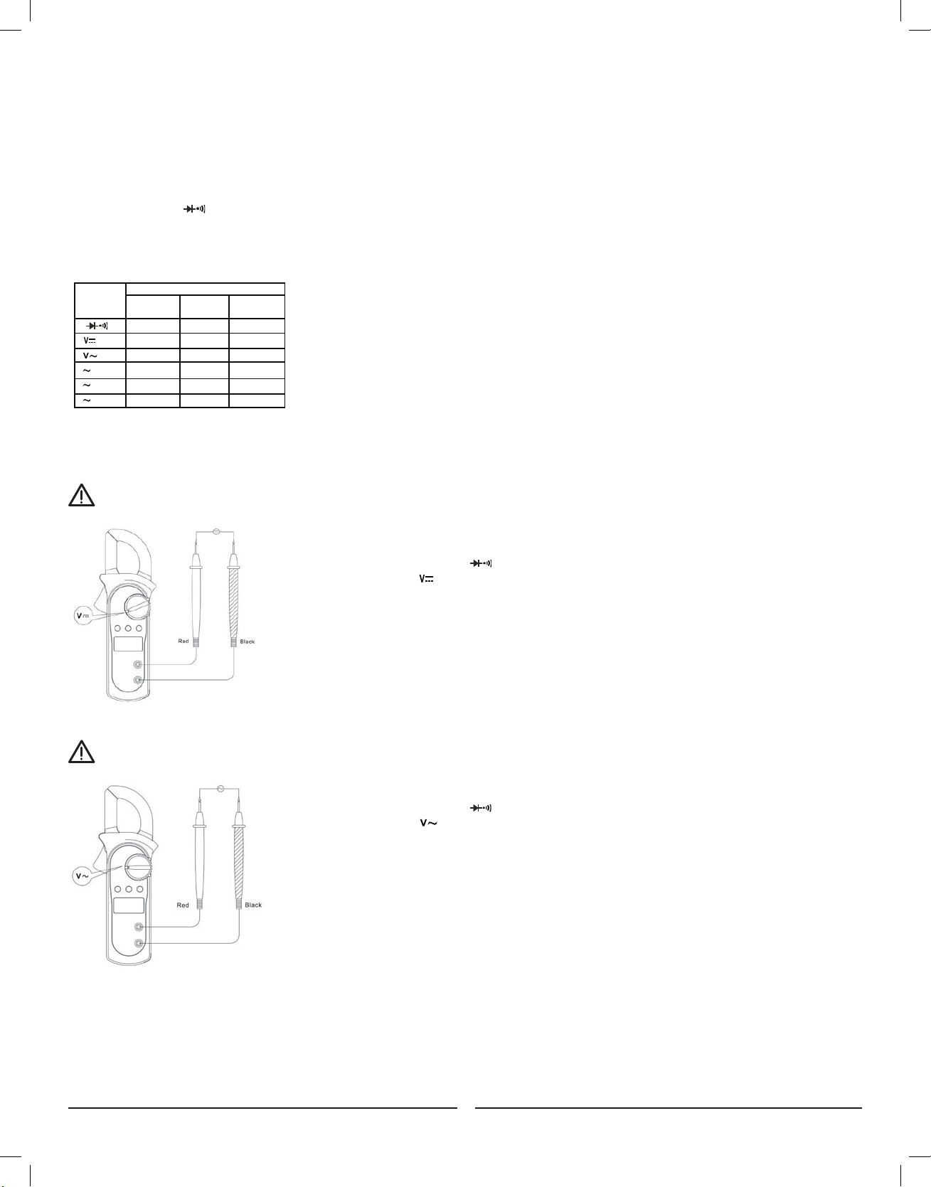
V. MEASUREMENT OPERATION
A. Measuring DC Voltage (See Figure 3)
To avoid harm to you or damage to the Meter from electric shock, do not attempt to measure
voltages higher than 600V AC/DC.
To measure DC voltage, connect the Meter as follows:
1. Insert the red test lead into the terminal and the black test lead into the COM terminal.
2. Set the rotary switch to
3. Connect the test leads across with the object being measured.
The measured value shows on the display.
NOTE:
When DC voltage measurement has been
completed, disconnect the connection between
the testing leads and the circuit under test and
remove testing leads from the input terminals.
Figure 3
Figure 2
Figure 4
Figure 5
Figure 6
Figure 7
Figure 8
Figure 9
Figure 7
International Electrical Symbols
AC (Alternating Current)
DC (Direct Current)
Grounding
Double Insulated
Warning. Refer to the Operating Manual
Low Battery Indication
Continuity Test
Diode
Conforms to Standards of European Union
Number
Description
1 Indicator for AC voltage or current
2 Indicator for DC voltage
3 The battery is low.
Warning: To avoid false readings, which
could lead to possible electric shock or
personal injury, replace the battery as soon as
the battery indicator appears.
4 The Meter is in the auto range mode in
which the Meter automatically selects
the range with the best resolution.
5 Test of diode
6 The continuity buzzer is on
7 Maximum reading displayed
8 Data hold is active
9 Amperes (amps). The unit of current.
10 Ω: Ohm. The unit of resistance.
kΩ:Kilohm. 1000 ohms
MΩ:Megohm. 1,000,000 ohms
11 V: Volts. The unit of voltage.
mV: Millivolt. 0.001 volts
12 Indicates negative reading
Rotary Functional Buttons
Switch SELECT MAX HOLD
Positions
Ω • N/A •
N/A • •
N/A • •
A 20A N/A • •
A 200A N/A • •
A 600A N/A • •
A. AC Voltage: Auto Ranging
Range Resolution Accuracy
2.000V 1mV
20.00V 10mV ±(1.2%+5)
200.0V 100mV
600V 1V ±(1.5%+5)
B. DC Voltage: Auto Ranging
Range Resolution Accuracy
200.0mV 0.1mV ±(0.8%+3)
2.000V 1mV
20.00V 10mV ±(0.8%+1)
200.0V 100mV
600V 1V ±(1%+3)
Remarks:
● Input impedance: 10MΩ
● Overload protection: 600V rms
C. Resistance: Auto Ranging
Range Resolution Accuracy
200.0Ω 100mΩ ±(1.2%+2)
2.000kΩ 1Ω
20.00kΩ 10Ω ±(1%+2)
200.0kΩ 100Ω
2.000MΩ 1kΩ ±(1.2%+2)
20.00MΩ 10kΩ ±(1.5%+2)
Remark:
● Overload protection: 600Vp
D. Continuity
Range Resolution Accuracy
Around <10Ω,the
buzzer beeps.
Remark:
● Overload Protection: 600Vp
● Open circuit voltage approximate 0.45V.
● The buzzer may or may not beeps when the
resistance of a circuit under test is more
than 10Ω.
E. Diode
Range Resolution Accuracy
Display approximate
forward voltage drop
Remarks:
● Overload Protection: 600Vp
● Open circuit voltage approximate 1.48V.
1mV
100mΩ
F. AC Current: Auto Ranging
Range Resolution Accuracy
20.00A 0.01A ±(2.0%+5)
200.0A 0.1A ±(1.5%+5)
600A 1A ±(2.0%+8)
Remarks:
IV. FUNCTIONAL BUTTONS AND AUTO POWER OFF
1. HOLD: Press the HOLD button to enter & exit the hold mode. Press and hold the HOLD button while turning the Meter on,
the auto power off function will be disabled.
2. AUTO POWER OFF: To preserve the battery life of the Meter, the Meter will automatically go into a "Sleep" mode if you
do not use the device for around 10 minutes. The Meter can be activated by pressing any of the Function Buttons
(refer to #6 Button Functions), then return to the display to view the function.
3. MAX: Press MAX to start recording and updating of maximum values.
4. SELECT: Under functions, the resistance setting will always be the default function.
Press the SELECT button to select the continuity or diode measurement mode.
5. BUZZER: The buzzer will sound every time a function button is pressed. The buzzer will also sound off with 5 "beeps"
approximately 1 minute before the Meters auto power off turns the Meter off.
6. BUTTON FUNCTIONS: The below table describes which function button can be used in regards to the position of the rotary switch.
International Electrical Symbols
AC (Alternating Current)
DC (Direct Current)
Grounding
Double Insulated
Warning. Refer to the Operating Manual
Low Battery Indication
Continuity Test
Diode
Conforms to Standards of European Union
Number
Description
1 Indicator for AC voltage or current
2 Indicator for DC voltage
3 The battery is low.
Warning: To avoid false readings, which
could lead to possible electric shock or
personal injury, replace the battery as soon as
the battery indicator appears.
4 The Meter is in the auto range mode in
which the Meter automatically selects
the range with the best resolution.
5 Test of diode
6 The continuity buzzer is on
7 Maximum reading displayed
8 Data hold is active
9 Amperes (amps). The unit of current.
10 Ω: Ohm. The unit of resistance.
kΩ:Kilohm. 1000 ohms
MΩ:Megohm. 1,000,000 ohms
11 V: Volts. The unit of voltage.
mV: Millivolt. 0.001 volts
12 Indicates negative reading
Rotary Functional Buttons
Switch SELECT MAX HOLD
Positions
Ω • N/A •
N/A • •
N/A • •
A 20A N/A • •
A 200A N/A • •
A 600A N/A • •
A. AC Voltage: Auto Ranging
Range Resolution Accuracy
2.000V 1mV
20.00V 10mV ±(1.2%+5)
200.0V 100mV
600V 1V ±(1.5%+5)
B. DC Voltage: Auto Ranging
Range Resolution Accuracy
200.0mV 0.1mV ±(0.8%+3)
2.000V 1mV
20.00V 10mV ±(0.8%+1)
200.0V 100mV
600V 1V ±(1%+3)
Remarks:
● Input impedance: 10MΩ
● Overload protection: 600V rms
C. Resistance: Auto Ranging
Range Resolution Accuracy
200.0Ω 100mΩ ±(1.2%+2)
2.000kΩ 1Ω
20.00kΩ 10Ω ±(1%+2)
200.0kΩ 100Ω
2.000MΩ 1kΩ ±(1.2%+2)
20.00MΩ 10kΩ ±(1.5%+2)
Remark:
● Overload protection: 600Vp
D. Continuity
Range Resolution Accuracy
Around <10Ω,the
buzzer beeps.
Remark:
● Overload Protection: 600Vp
● Open circuit voltage approximate 0.45V.
● The buzzer may or may not beeps when the
resistance of a circuit under test is more
than 10Ω.
E. Diode
Range Resolution Accuracy
Display approximate
forward voltage drop
Remarks:
● Overload Protection: 600Vp
● Open circuit voltage approximate 1.48V.
1mV
100mΩ
F. AC Current: Auto Ranging
Range Resolution Accuracy
20.00A 0.01A ±(2.0%+5)
200.0A 0.1A ±(1.5%+5)
600A 1A ±(2.0%+8)
Remarks:
*Not every functional button can be used on every rotary switch position.
WARNING
B. Measuring AC Voltage (See Figure 4)
To avoid harm to you or damage to the Meter from eletric shock, do not attempt to measure voltages higher than 600V AC/DC.
To measure AC voltage, connect the Meter as follows:
1. Insert the red test lead into the terminal and the black test lead into the COM terminal.
2. Set the rotary switch to
3. Connect the test leads across with the object being measured.
The measured value shows on the display.
NOTE:
When AC voltage measurement has been
completed, disconnect the connection between
the testing leads and the circuit under test and
remove testing leads from the input terminals.
International Electrical Symbols
AC (Alternating Current)
DC (Direct Current)
Grounding
Double Insulated
Warning. Refer to the Operating Manual
Low Battery Indication
Continuity Test
Diode
Conforms to Standards of European Union
Number
Description
1 Indicator for AC voltage or current
2 Indicator for DC voltage
3 The battery is low.
Warning: To avoid false readings, which
could lead to possible electric shock or
personal injury, replace the battery as soon as
the battery indicator appears.
4 The Meter is in the auto range mode in
which the Meter automatically selects
the range with the best resolution.
5 Test of diode
6 The continuity buzzer is on
7 Maximum reading displayed
8 Data hold is active
9 Amperes (amps). The unit of current.
10 Ω: Ohm. The unit of resistance.
kΩ:Kilohm. 1000 ohms
MΩ:Megohm. 1,000,000 ohms
11 V: Volts. The unit of voltage.
mV: Millivolt. 0.001 volts
12 Indicates negative reading
Rotary Functional Buttons
Switch SELECT MAX HOLD
Positions
Ω • N/A •
N/A • •
N/A • •
A 20A N/A • •
A 200A N/A • •
A 600A N/A • •
A. AC Voltage: Auto Ranging
Range Resolution Accuracy
2.000V 1mV
20.00V 10mV ±(1.2%+5)
200.0V 100mV
600V 1V ±(1.5%+5)
B. DC Voltage: Auto Ranging
Range Resolution Accuracy
200.0mV 0.1mV ±(0.8%+3)
2.000V 1mV
20.00V 10mV ±(0.8%+1)
200.0V 100mV
600V 1V ±(1%+3)
Remarks:
● Input impedance: 10MΩ
● Overload protection: 600V rms
C. Resistance: Auto Ranging
Range Resolution Accuracy
200.0Ω 100mΩ ±(1.2%+2)
2.000kΩ 1Ω
20.00kΩ 10Ω ±(1%+2)
200.0kΩ 100Ω
2.000MΩ 1kΩ ±(1.2%+2)
20.00MΩ 10kΩ ±(1.5%+2)
Remark:
● Overload protection: 600Vp
D. Continuity
Range Resolution Accuracy
Around <10Ω,the
buzzer beeps.
Remark:
● Overload Protection: 600Vp
● Open circuit voltage approximate 0.45V.
● The buzzer may or may not beeps when the
resistance of a circuit under test is more
than 10Ω.
E. Diode
Range Resolution Accuracy
Display approximate
forward voltage drop
Remarks:
● Overload Protection: 600Vp
● Open circuit voltage approximate 1.48V.
1mV
100mΩ
F. AC Current: Auto Ranging
Range Resolution Accuracy
20.00A 0.01A ±(2.0%+5)
200.0A 0.1A ±(1.5%+5)
600A 1A ±(2.0%+8)
Remarks:
Figure 3
Figure 2
Figure 4
Figure 5
Figure 6
Figure 7
Figure 8
Figure 9
Figure 7
Loading ...
Loading ...
Loading ...