EN
BIASUMEN--003
www.bora.com
Operating and assembly instructions BIAS (BIA, BIU)
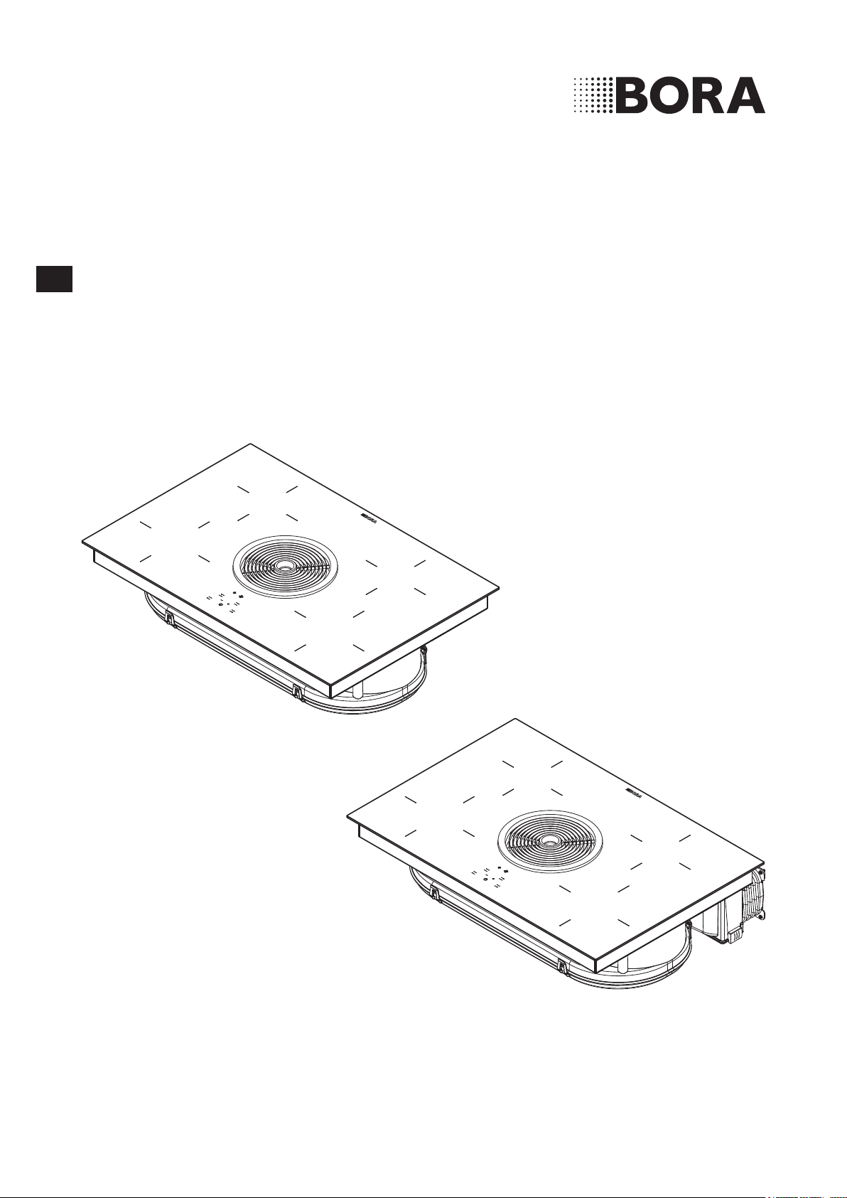
BORA Basic induction-glass-ceramic-cooktop with
cooktop extractor – exhaust/recirculation

Operating and installation instructions: Original Translation
Manufacturer
BORA Vertriebs GmbH & Co KG
Innstraße 1
6342 Niederndorf
Austria
Contact
T +43 (0) 5373 / 62250-0
www.bora.com
The distribution and duplication of this document, as well as the use and disclosure of its contents are prohibited
unless expressly authorised.
These operating and installation instructions have been drawn up with the greatest of care. But it cannot be ruled
out that subsequent technical modifications have not yet been incorporated or the relevant content has not yet been
adapted. Please accept our apologies in this eventuality. An updated version can be requested from the BORA Service
Team. Subject to printing errors and mistakes.
© BORA Vertriebs GmbH & Co KG
All rights reserved.

EN
3
www.bora.com
Table of Contents
1 General information 4
1.1 Target group ................................................................ 4
1.2
Validity of the operating and installation instructions
...4
1.3 Other applicable documents ......................................4
1.4 Presentation of information ........................................5
2 Safety 6
2.1 General safety instructions ......................................... 6
2.2 Safety instructions – operation ..................................7
2.3 Safety instructions – installation ..............................10
2.4 Safety instructions – disassembly and disposal ......11
2.5 Safety instructions – spare parts .............................11
2.6 Intended use .............................................................11
3 Technical data 12
4 Energy label 14
5 Device description 15
5.1 Structure ...................................................................15
5.2 Operating panel and operating principle ..................16
5.3 How the cooking zone works ..................................16
5.3.1 Power levels ..............................................................17
5.3.2 power setting ............................................................17
5.3.3 Timer functions .........................................................17
5.3.4 Pan size recognition ..................................................17
5.3.5 Suitable cookware ....................................................17
5.4 How the cooktop extractor works ............................18
5.4.1 power setting ............................................................18
5.4.2 Automatic after-run ...................................................18
5.4.3 Filter service display .................................................18
5.5 Safety devices ...........................................................18
5.5.1 Residual heat display ................................................18
5.5.2 Safety shut-down ......................................................18
5.5.3 Overheating protection .............................................18
5.5.4 Automatic switch-off if the button is
pressed and held ......................................................18
5.5.5 Child safety lock........................................................18
6 Assembly 19
6.1 Checking the scope of delivery ................................19
6.2 Tool and aids .............................................................19
6.3 Assembly instructions ...............................................19
6.3.1 Safety distances ........................................................19
6.3.2 Work surface and kitchen units ................................19
6.3.3 Cooktop air intake ....................................................20
6.4 Dimensions of cut-out for cooktop...........................20
6.5 Attaching the sealing tape ........................................21
6.6 Installing the air recirculation version (BIU) .............21
6.7 Installing exhaust air duct variant (BIA) ....................24
6.7.1 Using the cooktop extractor with a fireplace
which does not depend on room air ........................24
6.8 Establishing the power connection ..........................28
6.9 Handover to user ......................................................29
7 Operation 30
7.1 Switching cooktop on/off ........................................30
7.1.1 Switching on the cooking zone ................................30
7.1.2 Adjusting the power level .........................................30
7.1.3 Changing the power level .........................................30
7.1.4 Switching on the power setting ................................30
7.1.5 Switching the power setting off early .......................30
7.1.6 Switching off the cooking zone ................................30
7.1.7 Pay attention to the residual heat display ................30
7.1.8 Using the timer function ...........................................30
7.1.9 Activating/deactivating the child safety lock ..........31
7.2 Operating the cooktop extractor ..............................32
7.2.1 Switching on the cooktop extractor .........................32
7.2.2 Setting the fan level ..................................................32
7.2.3 Switching on the delayed automatic after-run .........32
7.2.4 Switching off the cooktop extractor .........................32
7.3 Pay attention to the filter service display .................32
7.4 Saving energy ............................................................33
8 Cleaning and maintenance 34
8.1 Cleaning agents ........................................................34
8.2 Maintaining the cooktop ...........................................34
8.3 Cleaning the cooktop ................................................34
8.4 Cleaning the cooktop extractor ................................35
8.4.1 Removing the air inlet nozzle and stainless steel
grease filter ...............................................................35
8.4.2 Cleaning the air inlet nozzle and stainless steel
grease filter ...............................................................35
8.4.3 Installing stainless steel grease filter and
air inlet nozzle ...........................................................35
8.5 Cleaning the air guiding housing ..............................35
8.5.1 Opening the air guiding housing ...............................35
8.5.2 Closing the air guiding housing ................................36
8.6 Replacing the activated charcoal filter .....................36
9 Troubleshooting 38
10 Decommissioning, disassembly and
disposal 39
10.1 Decommissioning......................................................39
10.2 Disassembly ..............................................................39
10.3 Environmentally-friendly disposal .............................39
11 Warranty, technical service,
spare parts, accessories 40
11.1 Warranty ....................................................................40
11.2 Service .......................................................................40
11.3 Replacement parts ....................................................40
11.4 Accessories ...............................................................40
12 Notes 41

EN
4
General information
www.bora.com
1 General information
1.1 Target group
These operating and installation instructions apply for the
following target groups:
Target group Requirements
User The appliance can be used by children
aged 8 and above as well as people with
reduced physical, sensory or mental
capacities or a lack of experience and/or
knowledge if they are supervised or have
been instructed how to safely use the
appliance and understand the resultant
risks. Children must be supervised. All
safety and warning information and the
handling instructions in the installation
instructions must be complied with.
Ambitious DIYers Ambitious DIYers can independently
conduct all joinery and installation work
providing they possess the necessary
skills and expertise. They must never
independently establish electricity and
gas connections.
Installation specialists Installation specialists are authorised
to conduct all joinery and installation
work in line with
existing regulations. The
electricity and gas connections must be
certified by a certified engineer for the
applicable trade prior to commissioning.
Electricians The electrical connection may only be
established by a certified engineer.
He/she also assumes responsibility for
the proper electrical installation and
commissioning.
Gas specialists The gas connection may only be
established by certified engineers.
They also assume responsibility for
proper installation and commissioning of
the gas system.
Tab. 1.1 Target groups
INFO BORA Holding GmbH, BORA Vertriebs GmbH
& Co KG, BORA APAC Pty Ltd and BORA
Lüftungstechnik GmbH - hereinafter referred
to as BORA - do not assume any liability for
damage arising from non-adherence to these
documents and from improper assembly! The
electricity and gas connections must be made
by a qualified specialist. Installation must
comply with the valid standards, regulations
and laws. All safety and warning information
and the operating and installation instructions
must be complied with.
1.2 Validity of the operating and
installation instructions
These instructions apply to several device versions. It is
therefore possible that some of the features described do
not apply to your appliance.
1.3 Other applicable documents
These operating and installation instructions are valid
in conjunction with other documents, which must be
adhered to.
Please be sure to adhere to all documents that form part
of the scope of delivery.
INFO BORA accepts no liability for damage caused
by failure to comply with these documents!
Directives
This device meets the following EU/EC directives:
2014/30/EU EMC Directive
2014/35/EU Low Voltage Directive
2009/125/EC Ecodesign Directive
2010/30/EU Energy Consumption Label Directive
2011/65/EU RoHS Directive
2012/19/EU WEEE Directive
EN
5
General information
www.bora.com
1.4 Presentation of information
To make working with these instructions quick and
easy, consistent formatting, numbering, symbols,
safety instructions, terms and abbreviations are used
throughout.
Handling instructions are market with an arrow.
Always carry out handling instructions in the sequence
shown.
Bullet points are indicated by a square bullet point at
the edge of the line.
Bullet point 1
Bullet point 2
INFO Information points out specific points you must
always comply with.
Safety and warning information
The safety and warning information in these instructions
are highlighted with symbols and signal words.
Safety and warning information is structured as follows:
WARNING SYMBOL AND SIGNAL
WORD!
Type and source of the danger
Consequences of non-compliance
Measures to minimise risk
The following applies:
The warning symbol draws attention to the danger.
The signal word indicates the severity of the risk.
Warning sign Signal word Hazard
Danger Indicates an imminent hazardous
situation which could lead to
death or serious injury
if ignored.
Warning Indicates an imminent hazardous
situation which could lead to
death or serious injury if
ignored.
Caution Indicates a potentially hazardous
situation which could lead to slight
or minor injuries if ignored.
— Caution Indicates a situation which could
result in material damage if
ignored.
Tab. 1.2 Meaning of warning symbols and signal words

EN
6
Safety
www.bora.com
2 Safety
2.1 General safety instructions
INFO The appliance complies with the
stipulated safety requirements. The
user is responsible for appliance
cleaning and maintenance as well as
its safe use. Improper use can lead
to personal injury and damage to
property.
The operating and installation instructions
contain important information about
installation and operation. These enable you
to protect yourself against injuries and
prevent damage to the appliance. Contact
details for further information as well as
application and usage questions can be
found on the back of these operating and
installation instructions.
The term device applies to cooktops,
cooktop extractors and cooktops with
cooktops extractors.
Read the operating and installation
instructions fully before using the appliance
for the first time.
Always store the operating and installation
instructions within easy reach so that they
can be accessed if required.
Pass the operating and installation
instructions to the next owner if you sell
the appliance.
Conduct all work extremely attentively and
conscientiously.
Check the appliance for visible damage
when unpacking it.
Do not connect a damaged appliance.
Only use the appliance once all installation
activities are complete. This is the only way
to ensure safe operation.
Make sure that hot hobs are not touched.
Avoid boiling over.
Pay attention to the residual heat display.
Switch the device off after use.
Do not rely on the pan size recognition.
Keep pets away from the appliance.
CAUTION!
Risk of injury from falling device
components!
Falling device components such
as pan supports, control elements,
covers, grease lters, etc. can cause
injuries.
Place device components safely
near the devices after you remove
them.
Make sure that none of the device
components you have removed
could fall.
Recirculation mode
INFO When cooking, additional moisture is
released into the ambient air.
INFO In recirculation mode, only a slight
amount of moisture is removed from
the cooking vapour.
When using recirculation mode, ensure a
sufficient supply of fresh air, e.g. by
opening a window.
Ensure a normal and comfortable room
climate (humidity of 45–60%), e.g. by
opening natural ventilation openings or
using domestic ventilation systems.
After every use in recirculation mode,
switch the cooktop extractor to a low level
for about 20 minutes or activate the
automatic after-run function.
Effect on pacemakers, hearing aids and
metallic implants
INFO Induction cooktops generate a high-
frequency electromagnetic field near
the cooking zones. Coming too close
to the cooking zones could have a
negative influence or even cause
malfunctions of pacemakers, hearing
aids or metallic implants. Issues with
pacemakers are unlikely.
In case of doubt, please contact the
manufacturer of your medical device or
your doctor.
EN
7
Safety
www.bora.com
Do not put hot cookware near the control
panel so as not to damage the electronics
underneath.
Make sure no water penetrates inside the
device when cleaning. Only use a slightly
damp cloth. Never spray water on the
device. Water ingress can cause damage!
Where possible, clean the cooktop after
every cooking session.
Only clean the cooktop when it has cooled
down.
For cleaning, only use non-abrasive
detergents to avoid scratching or wearing
the surface.
Make sure the base of the cookware and
the cooking zone are clean and dry.
Always lift the cookware (do not pull) to
avoid scratching or wearing the surface.
Do not place hot cookware on the air inlet
nozzle of the cooktop extractor.
Make sure that hot cookware does not
come into contact with the edge of the air
inlet nozzle.
2.2 Safety instructions – operation
Cooktop
DANGER!
Unsupervised cooktops are a fire
risk!
Oil and fat can heat up and catch re
quickly.
Never leave hot oil or fat
unattended.
Never attempt to extinguish
burning oil or fat with water.
Stifle the fire using a lid, for
example.
DANGER!
Risk of explosion caused by
flammable liquids!
Flammable liquids in the vicinity of
the cooktop can explode and cause
serious injury.
Do not place any flammable liquids
in the vicinity of the cooktop.
Households with children and people with
special needs
The appliance can be used by children aged
8 and above as well as people with reduced
physical, sensory or mental capacities or a
lack of experience and/or knowledge if
they are supervised or have been instructed
how to safely use the appliance and
understand the resultant risks.
Supervise children in the vicinity of the
appliance.
Children must not play with the appliance.
Use the childproofing feature to prevent
children accidentally switching the cooktop
on or changing the settings.
Do not store any items that could be of
interest to children in storage spaces above
or behind the appliance. Children will
otherwise be encourage to climb on the
appliance.
Keep children and other people away from
hot hobs.
Unauthorised modifications
Unauthorised modifications can cause the
appliance to pose risks.
Do not conduct any modifications to the
appliance.
Cleaning and maintenance
The device must be cleaned regularly. Dirt
can lead to damage or the buildup of odours.
Remove any dirt immediately.
Cleaning and maintenance work must not
be carried out by children unless they are
supervised at all times.
Do not use steam cleaners. The steam can
cause a short-circuit on live parts and
cause damage to property (see Cleaning
and maintenance section).
EN
8
Safety
www.bora.com
WARNING!
Risk of burns from hot cookware!
Handles projecting over the edge are
enticing for children to grab.
Do not turn pot and pan handles
so they stick out beyond the work
surface.
Make sure that children cannot
pull hot pots and pans over.
A special stove guard for children
(available from specialist suppliers)
reduces the risk.
WARNING!
Risk of getting burnt!
Liquid between the cooking zone
and the pan base can evaporate and
cause burns.
Make sure that the cooking zone
and the pan base are always dry.
CAUTION!
Damage from hard and pointed
objects!
Hard and pointed objects can
damage the glass ceramic panel of
the cooktop!
Do not use the surface of the
cooktop as a worktop.
Do not use hard and pointed
objects when working on the
cooktop.
CAUTION!
Damage from sugary and salty
foods!
Sugary and salty foods and juices
can damage the hot cooking zone.
Make sure sugary and salty foods
or juices do not get onto the
cooking zone while it is hot.
Remove sugary and salty foods
and juices from the hot cooking
zone.
CAUTION!
Escaping hot liquids!
Unattended pans can boil over
allowing hot liquids to escape.
Always keep an eye on pans while
cooking.
Short cooking sessions must be
constantly monitored.
DANGER!
Risk of electric shock!
Chips, cracks or breaks in the glass
ceramic panel can expose or damage
the electronics underneath. This can
lead to an electric shock.
If the glass ceramic panel gets
chipped, broken or cracked, switch
the cooktop off immediately.
Securely disconnect the appliance
from the mains using LS switches,
fuses, automatic circuit breakers
or contactors.
WARNING!
Risk of burns from hot cooktop!
The cooktop and its exposed areas
get hot during use. Once the cooking
zone is switched o, it takes a little
while to cool down below 60 °C.
Touching hot surfaces can cause
serious burns.
Never touch the cooktop when it
is hot.
Keep children away from the
cooktop when it is hot or ensure
they are supervised at all times.
WARNING!
Leaving items on the cooking
surface is a fire risk!
The cooktop and its touchable parts
are hot when the cooking zone is
switched on and during the cooling
phase. Objects on the cooktop can
get hot and catch re.
Do not place any items on the
cooktop.
WARNING!
Risk of burns from hot items!
The cooktop and its touchable parts
are hot during both operation and the
cooling phase. Items placed on the
cooktop heat up very quickly and can
cause severe burns. This particularly
applies to metal items (e.g. knives,
forks, spoons, lids or cooktop
extractor covers).
Do not place any items on the
cooktop.
Please use suitable tools (pot
holders, oven gloves).
EN
9
Safety
www.bora.com
CAUTION!
Damage from objects on the
cooktop!
Objects such as pan lids on the
cooktop can damage the glass
ceramics.
Do not leave objects on the hot
cooktop.
Cooktop extractor
DANGER!
Risk of smoke inhalation!
Using a replace that depends on the
air in the room produces combustion
gases.
If the cooktop extractor is used in
conjunction with a replace that
depends on the air in the room, toxic
combustion gases (carbon monoxide)
can be extracted from the chimney
or outlet duct into the living area.
Make sure that there is always a
sufficient air supply.
DANGER!
Fire risk from flambéing!
While the cooktop extractor is
working, it sucks up grease from
cooking. Flambéing food can cause
the grease to catch re.
Clean the cooktop extractor
regularly.
Never work with a naked flame
while the cooktop extractor is
running.
DANGER!
Fire risk from fat deposits!
If the stainless steel grease lter is
not cleaned regularly, this can lead to
increased levels of grease in it. This
increases the re risk.
Clean and replace the filter at
regular intervals.
CAUTION!
Touchable parts may become hot!
The cooktop extractor and its
touchable parts are hot when the
cooking zone is switched on and
during the cooling phase.
Do not place any items on the
cooktop.
Please use suitable tools
(pot holders, oven gloves).
WARNING!
There is a risk of injury when
opening the lower cover on the
housing!
There is a risk of injury if the fan
wheel turns.
Switch the cooktop extractor and
the cooktop off.
Switch off the fuse.
CAUTION!
Damage caused by objects or
paper suctioned in!
Small and light items, such as
cleaning cloths made from material
or paper, can be suctioned into
the cooktop extractor. This can
damage the fan or impair the exhaust
performance.
Do not store any items or paper on
the cooktop extractor.
CAUTION!
Damage caused by grease and dirt
deposits!
Grease and dirt deposits can stop the
cooktop extractor from functioning
properly.
Never use the cooktop extractor
without a stainless steel grease
filter.
EN
10
Safety
www.bora.com
2.3 Safety instructions – installation
The device must only be installed and
assembled by trained specialists who are
familiar with and comply with the standard
national regulations and supplementary
regulations of the local utility companies.
Work on electrical components must be
conducted by trained electrical personnel.
The electrical safety of the appliance is only
guaranteed if it is connected to a protective
conductor system that has been installed in
line with regulations. Ensure that this basic
safety precaution is met.
Cooktop
DANGER!
Risk of electric shock!
Incorrect connection of the device
to the mains voltage could cause
electric shocks.
Make sure that the device is firmly
connected to the mains voltage.
Make sure the device is connected
to a properly installed earth
conductor system.
Make sure a system is installed
which allows disconnection from
the network with a contact
opening width of at least 3 mm
across all poles (circuit breaker,
fuses, automatic circuit breakers,
contactors).
DANGER!
Risk of electric shock!
If the mains connection cable comes
into contact with hot hobs, it could
get damaged. A damaged mains
connection cable can cause a
(deadly) electric shock.
Make sure that the mains
connection cable cannot come
into contact with hot hobs.
Make sure that the connection
cable is not squashed or damaged.
CAUTION!
Lifting heavy loads can cause back
injuries!
If not correctly handled, removing
and installing the device can causes
injuries to the limbs or torso.
Removing the cooktop from the
packaging is a two-person job.
Placing the cooktop into the
worktop cut-out is a two-person
job.
Use appropriate aids to prevent
damage or injuries to limbs or
torso.
Cooktop extractor
DANGER!
Risk of poisoning from combustion
gases!
If the cooktop extractor is used in
exhaust mode, it draws in air from
the room in which it is installed as
well as from neighbouring rooms. If
there is insucient air supply, low
pressure will occur. Toxic gases
could be drawn out of the replace
that depends on the air in the room
or extraction ducting and back into
the room.
Make sure that there is always a
sufficient air supply.
Only use approved and tested
switchgear (e.g. window contact
switch, low-pressure monitor)
and have them approved by
authorised specialists (certified
chimney-sweep).
DANGER!
Risk of electric shock!
Incorrect stripping of the connection
cable to external switching devices
results in a risk of electric shock.
Ensure that the stated stripping
lengths are adhered to.
EN
11
Safety
www.bora.com
Check the appliance for visible damage
before installing it.
Do not install damaged devices.
A damaged device is a hazard.
Repair work must only be carried out by
specialists authorised by the manufacturer.
2.4 Safety instructions –
disassembly and disposal
The device must only be disassembled by
trained specialists who are familiar with and
comply with the standard national regulations
and supplementary regulations of the local
utility companies.
Work on electrical components must only be
conducted by trained electrical personnel.
DANGER!
Risk of electric shock!
Incorrectly disconnecting the
appliance from the mains results in a
risk of electric shock.
Securely disconnect the appliance
from the mains using LS switches,
fuses, automatic circuit breakers
or contactors.
Use an authorised measuring
device to ensure that there is no
power to the appliance.
DANGER!
Risk of asphyxiation!
Packaging components (e.g. lm,
polystyrene) can be life-threatening
for children.
Store all packaging components
out of reach of children.
Dispose of the packaging properly
and immediately.
2.5 Safety instructions – spare parts
WARNING!
Risk of injury and damage to
property!
Incorrect components can lead to
personal injury or damage to the
appliance. Modications, additions or
alterations to the appliance can lead
to safety risks.
Only use original spare parts for
repairs.
2.6 Intended use
The device cannot be used at altitudes above
2000 m (metres above sea level).
The device is designed exclusively for the
preparation of food in private households.
This appliance is not intended for:
Outdoor use
Installation in vehicles
Heating rooms
Use in non-stationary installation sites
(e.g. on ships)
Use with an external timer or a separate
remote control system (remote operation)
Any use other than that specified in these
operating and installation instructions or any
use that goes beyond that which is described
here is classed as unintended. BORA does not
assume any liability for damages caused by
improper use or incorrect operation.
All misuse is prohibited!
INFO BORA Holding GmbH, BORA Vertriebs
GmbH & Co KG, BORA APAC Pty Ltd
and BORA Lüftungstechnik GmbH do
not assume any liability for damage
arising from non-adherence
to the
safety and warning information.
EN
12
Technical data
www.bora.com
3 Technical data
Parameter Value
Supply voltage 380-415 V 3N
Frequency 50 Hz
Power consumption 7.6 kW
Fuse protection, minimum 1 x 32 A / 2 x 16 A
Total output 7.6 KW
Line-to-line voltage AC 220 – 240 V / 50 Hz
Main dimensions (width x depth x height)
(excl. duct connections)
760 x 515 x 196 mm
Weight (incl. accessories/packaging) Approx. 25 kg
Cooktop
Front single-ring induction cooking zones
210 mm 2300 W
power setting 3000 W
Back single-ring induction cooking zones
175 mm 1400 W
Power levels 1 – 9, power setting
Cooktop energy consumption
Cooking zone 1 (210 mm) 194,5 (Wh/kg)
Cooking zone 2 (175 mm) 181,1 (Wh/kg)
Cooking zone 3 (210 mm) 193,8 (Wh/kg)
Cooking zone 4 (175 mm) 184,1 (Wh/kg)
Total 188,4 (Wh/kg)
Extraction system (BIA)
Maximum flow volume 647 m
3
/h
Maximum static pressure 339 Pa
Power control 1 – 2, power setting
Exhaust air connection (BIA) 222 x 40 x 89 mm
Recirculation system (BIU)
Maximum flow volume 624 m
3
/h
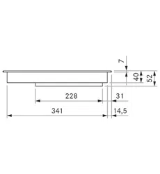
Maximum static pressure 341 Pa
Power control 1 – 2, power setting
Recirculation connection (BIU) 650 x 90 mm
Recirculation filter
Filter area 2 x 0.4m
2
Filter capacity 150 operating hours
Service life 1 year
Tab. 3.1 Technical data
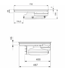
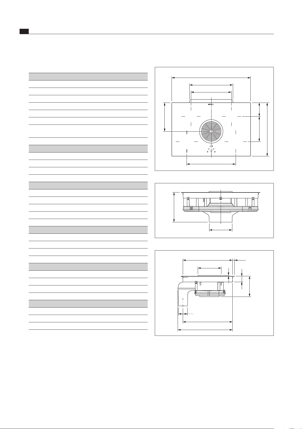
Device dimensions BIA
390
515
418
132242
760
275
471
Fig. 3.1 BIA Device dimensions aerial view
245
290
Fig. 3.2 BIA Device dimensions front view
89
Ø222
484
496
56
196
6
15,5
547
Fig. 3.3 BIA Device dimensions side view
EN
13
Technical data
www.bora.com
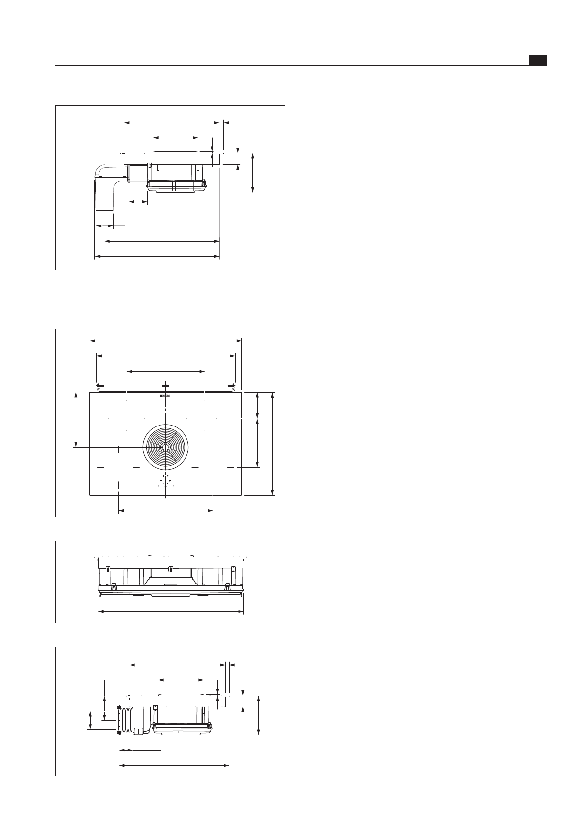
89
Ø222
484
596
56
196
6
15,5
647
100
Fig. 3.4 Device dimensions with cable extension
(BIA + BLAVH1)
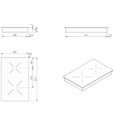
Device dimensions BIU
650
390
515
275
132
242
760
471
Fig. 3.5 BIU Device dimensions aerial view
727
Fig. 3.6 BIU Device dimensions front view
45–105
Ø222
484
525–585
56
196
6
90
119
15,5
Fig. 3.7 BIU Device dimensions side view
EN
14
Energy label
www.bora.com
4 Energy label
Product description
Glass ceramic cooktop with 4 cooking zones and an
integrated cooktop extractor
BIA BIU
Operating mode
Exhaust air Recirculation
Energy consumption
Value Value EN standard
Annual energy consumption (AEC
hood
) 87,5 kWh/a 94,2 kWh/a 61591
Energy efficiency class
C * 61591
Flow volume
Fluid dynamic efficiency (FDE
hood
) 15,7 13,1 61591
Fluid dynamic efficiency class
D * 61591
Lighting
Lighting efficiency (LE
hood
) * lx/Watt * lx/Watt *
Lighting efficiency class
* * *
Grease filtering
Level 2 maximum (GFE
hood
) 88,5 % 88,5 % 61591
Class level 2 normal
B * 61591
Grease filtering (additional details)
Level P maximum (GFE
hood
) 93 % 93 % 61591
Class level P maximum
B * 61591
Flow volume
Air flow level 1 minimum
342 m³/h * m³/h 61591
Air flow level 2 normal
497 m³/h * m³/h 61591
Air flow level P maximum (Q
max
) 647 m³/h 624 m³/h 61591
Sound power level
Level 1 minimum
55 dB(A) * dB(A) 60704-2-13
Level 2 normal
64 dB(A) 65 dB(A) 60704-2-13
Level P maximum
69 dB(A) 70 dB(A) 60704-2-13
Sound pressure level (additional details)
Level 1 minimum
43 dB(A) * dB(A) **
Level 2 normal
51 dB(A) 53 dB(A) **
Level P maximum
57 dB(A) 57 dB(A) **
Details according to 66/2014
Power consumption in off mode (P
O
) < 0,5 W < 0,5 W 61591
Time increase factor
1,4 1,5 61591
Energy efficiency index (EEI
hood
) 79,9 85,6 61591
Air flow rate at the best efficiency point (Q
BEP
) 370,8 m³/h 320,8 m³/h 61591
Pressure at the best efficiency point (P
BEP
) 261 Pa 253 Pa 61591
Electric power input at the best efficiency point (W
BEP
) 171,2 W 172,1 61591
Tab. 4.1 Energy label details
(The recirculation information is optional and not subject to mandatory inclusion on the label)
* This specification is not applicable for this product.
** The sound pressure level has been determined from a distance of 1 m (distance-dependent level recording) on the
basis of the sound power levels established in EN 60704-2-13.
EN
15
Device description
www.bora.com
5 Device description
Observe all safety and warning information during
operation (see the Safety chapter).
The cooktop with cooktop extractor has the following
features:
Cooktop:
power setting
Timer functions
Residual heat display
Pan size recognition
Child safety lock
Safety shut-down
Cooktop extractor:
Touch-operated power control
Automatic after-run (20 minutes)
Safety shut-down
Filter service display
Depending on your purchase decision, the cooktop
extractor is operated as an exhaust air or a recirculating
version.
Exhaust operation
The air suctioned away by the cooktop is purified by the
stainless steel grease filter and expelled into the open air
via a duct system.
The exhaust air must not be expelled into:
a smoke or exhaust gas flue that is in operation
a shaft used to aerate areas in which fireplaces are
installed
If the exhaust air is fed into a smoke or exhaust air flue
that is not in operation, the installation must be checked
and approved by a qualified heating engineer.
Recirculated air mode
The air suctioned away by the cooktop is purified by the
stainless steel grease filter and an activated charcoal
filter and fed back into the room in which the appliance is
installed.
To prevent odours in the recirculated air, an activated
charcoal filter must be used. For hygiene and health
reasons, the activated charcoal filter must be replaced
at the recommended intervals (see the Cleaning and
maintenance section).
INFO When using recirculated air, always ensure
sufficient ventilation and aeration to expel any
humidity.
The filter in the activated charcoal filter is made from
special activated charcoal, which is ideal for trapping
cooking odours.
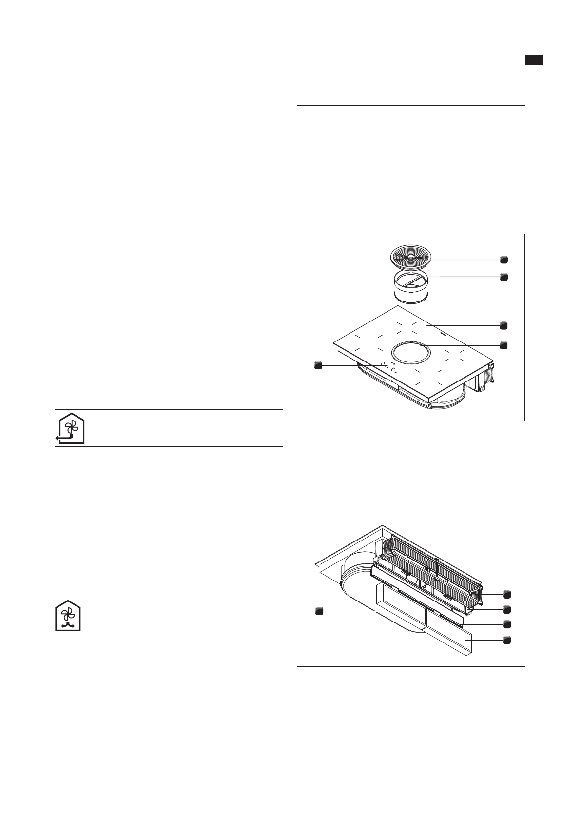
5.1 Structure
2
1
4
3
5
Fig. 5.1 Cooktop
[1] Inlet nozzle
[2] Stainless steel grease filter
[3] Cooktop
[4] Suction opening
[5] Operating panel
1
2
3
4
5
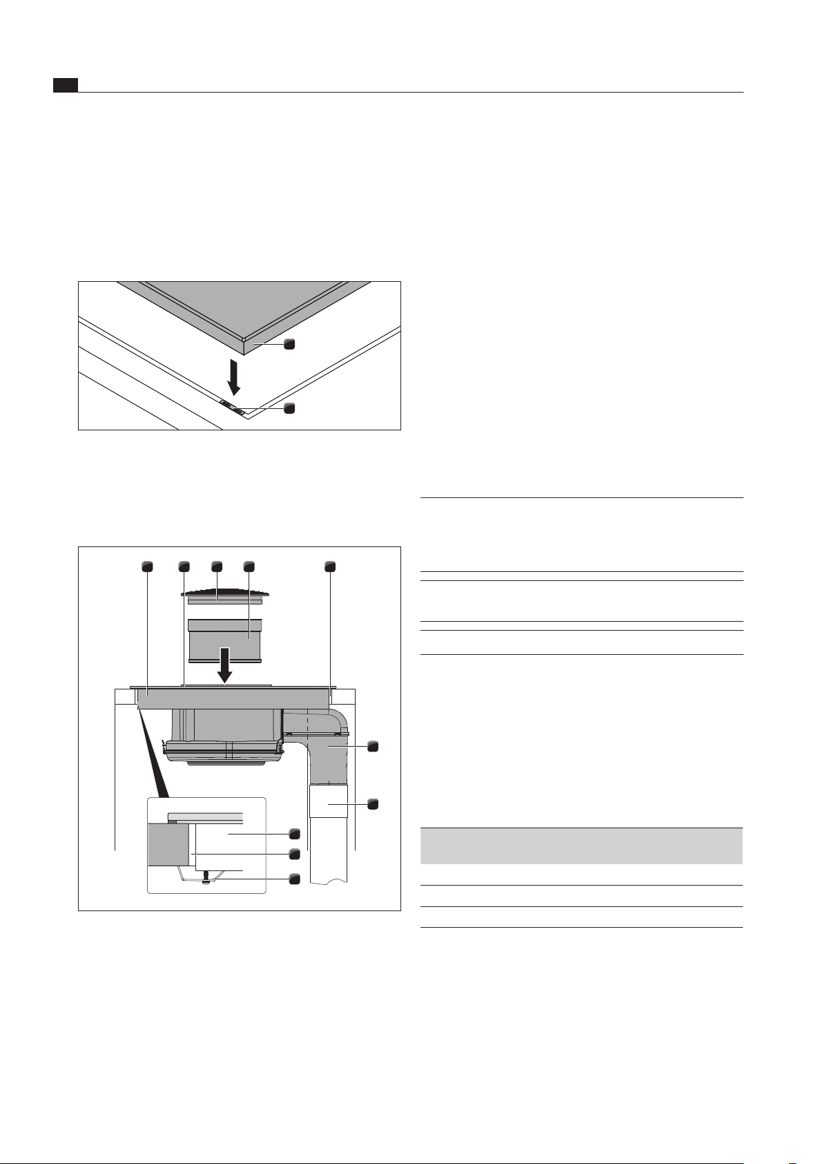
Fig. 5.2 Cooktop extractor recirculation (BIU)
[1] Flexible duct
[2] Activated charcoal filter housing
[3] Activated charcoal filter housing cover
[4] Activated charcoal filter
[5] Air guiding housing with housing base
EN
16
Device description
www.bora.com
Display fields:
[7] Fan level indicator/filter service display
[8] Cooking zone indicator light
[9] Cooking zone indicator
[10] Timer
Display panel Display Meaning
Fan level indicator
0
Fan off
1
or
2
Setting
P
power setting
n
Automatic after-run
Cooking zone
indicator
1
...
9
Power level
P
power setting
H
Residual heat display:
Cooking zone is
switched off but still hot
(temperature > 60°C)
L
Child safety lock active
Cooking zone
indicator light
On Automatic cut-off (timer)
activated
Flashes Timer on (00); no time set
Off Timer off
Timer display (1*)
0 1
...
99
Set minutes for short time
(egg timer) or automatic
cut-off
00
Timer on; no time set
Tab. 5.1 Meaning of displays
(1*) Timer display
The timer display uses the cooking zone indicators for
the two back cooking zones (e.g.
30
for 30 minutes).
The cooking zone indicators for the two front cooking
zones are disabled while the timer is displayed.
Touch control
The operating panel is fitted with electronic sensor
buttons and display panels. The sensor buttons respond
to finger contact.
You operate the device by touching the corresponding
sensor key with your finger. Keep the finger pressed on
the sensor key until you either hear an acoustic signal or
the display changes accordingly.
5.3 How the cooking zone works
An induction coil is located underneath an induction
cooktop. If the cooking zone is switched on, this coil
creates a magnetic field that acts directly on the base
of the pot thus heating it up. The cooking zone is only
indirectly heated up by the heat emitted by the pot.
Cooking zones with induction only work if the cookware
has a magnetisable base.
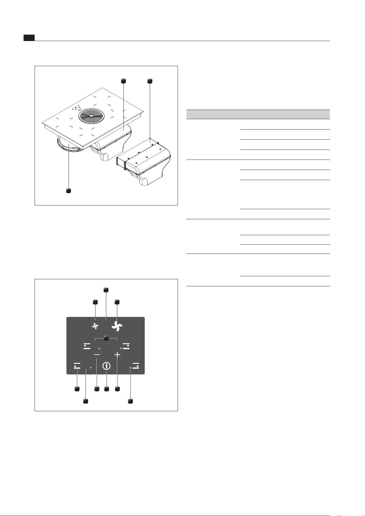
1
2
3
Fig. 5.3 Cooktop extractor exhaust air (BIA)
[1] Exhaust air arc with duct connection for BORA Ecotube
[2] Horizontal exhaust air extension
[3] Air guiding housing with housing base
5.2 Operating panel and operating
principle
2
46 3
9 8
5
7
1
10
Fig. 5.4 Operating panel
Sensor keys:
[1] Reduce fan power level
[2] Increase fan power level
[3] increase power level
[3] Increase timer value
[4] switch cooktop on/off
[5] reduce power level
[5] Decrease timer value
[6] Select cooking zone
EN
17
Device description
www.bora.com
5.3.3 Timer functions
You can use 2 timer functions:
Short-time timer (egg timer), no automatic switching
off of a cooking zone.
Automatic cut-off for automatically switching off a
cooking zone.
5.3.4 Pan size recognition
The cooking zone does not work
v
appears in the display.
If it is switched on without cookware or with unsuitable
cookware.
If the base diameter of the cookware is too small.
If the cookware is removed from a cooking zone that is
switched on.
5.3.5 Suitable cookware
INFO The heating and heat through time for the base
of the cookware as well as the cooking results
are significantly influenced by the structure and
material of the cookware.
Cookware with this symbol is suitable for
induction cooktops.
The cookware used for the induction cooktop
must be made of metal, feature magnetic prop-
erties and possess a sufficient bottom surface.
Suitable cookware is made of:
stainless steel with a magnetisable base
enamelled steel
cast iron
Cooking zone Minimum diameter
Front 120 mm
Back 90 mm
Tab. 5.3 Minimum cookware diameter
Perform a magnet test, if necessary. If a magnet sticks
to the base of the utensils, they are normally induction
compatible.
Pay attention to the cookware bottom. The base of
the cookware should not show any sign of curvature.
Due to incorrect temperature monitoring of the hob
caused by the air gap between the cookware and the
temperature sensor underneath the hob, overheating
may occur. The bottom of the cookware must not have
any sharp grooves or sharp edges to avoid scratching
the cooktop.
Place the cookware (without a mat or similar) directly
onto the glass ceramic.
Noises
The following noises may occur in the cookware when
using induction cooking zones, depending on the material
and the finish of the base:
The induction automatically takes into account the size of
the used cookware which means that only the area in the
cooking zone covered by the base of the pot is heated up.
Observe the minimum pot base diameter.
The cooking zone does not work
If it is switched on without cookware or with unsuitable
cookware.
If the base diameter of the cookware is too small.
If the cookware is removed from a cooking zone that is
switched on.
In the case of cookware that is unsuitable or too small,
v
appears in the cooking zone display.
5.3.1 Power levels
The high power output of induction cooktops results in
the very quick heating up of cookware. A slight adjust-
ment is needed in comparison to conventional cooking
systems when selecting the power level in order to avoid
burning food.
Activity Power level
Melting of butter and chocolate, breaking up gelatine 1
Keeping sauces and soups warm, soaking rice 1-3
Cooking potatoes, pasta, soups, ragouts, steaming
fruit, vegetables and fish, defrosting food
2-6
Frying in coated pans, moderate frying
(without overheating the fat) of pork cutlets, fish
6-7
Heating up fat, browning fish, cooking thickened
sources and soups, making omelettes
7-8
Cooking large quantities of liquid, browning steaks 9
Heating up water P
Tab. 5.2 Recommendations for power levels
The specifications provided in the table are standard
values.
Depending on the cookware and filling quantity, it is
recommended to either decrease or increase the power
level.
5.3.2 power setting
The two front cooking zones have a power-enhancing
power setting.
The power setting can be used in order to quickly heat up
large quantities of water. If the power level is activated,
the cooking zones will run at extra high power. After
5 minutes, the power level is automatically switched to
level
9
.
If one cooking zone is operated with the
P
power setting,
then the operation of the second cooking zone on this
side is possible at a maximum of power level
5
.
INFO Never heat up oil, fat and the like at this power
setting. The bottom of the pan can overheat
due to the high power output.

EN
18
Device description
www.bora.com
5.5.2 Safety shut-down
Cooking zone
Each cooking zone is switched off automatically when the
cooking zone in the power level exceeds the maximum
operating duration.
H
(residual heat display) is then displayed
in the cooking zone indicator (see the Device description
section).
Power level 1 2 3 4 5 6 7 8 9
Switch off after
x hours
8 6 5 5 4 1.5 1.5 1.5 1.5
Tab. 5.4 Overview of the safety shut-down
Switch the cooking zone back on (see Operating control)
if you want to put the cooking zone back into operation.
Cooktop extractor
The cooktop extractor switches off automatically if no
buttons are pressed for 120 minutes.
5.5.3 Overheating protection
The device is fitted with overheating protection.
The overheating protection can be triggered if:
Cookware is heated up empty.
Oil or fat is heated on high power.
A hot cooking zone is switched on again after a power cut.
There is insufficient ventilation below the cooktop (see
Cooktop air intake).
Before the overheating damages the electronics, one of the
following measures is taken:
The power level can no longer be increased.
The power level set is reduced.
The cooktop switches off completely.
After a sufficient cooling period, the cooktop can be used
again in full.
5.5.4 Automatic switch-off if the button is
pressed and held
The cooktop will be switched off automatically when
one or more sensor buttons are touched for longer than
10 seconds (finger contact, objects, soiling).
After a few seconds, the cooktop will switch off.
Remove the finger or object from the cooktop.
Clean the cooktop as required.
Where necessary, switch the cooktop back on.
5.5.5 Child safety lock
The child safety lock prevents the cooktop from being
switched on automatically. The child safety lock can only
be activated when the cooktop is switched on and all
cooking zones have been switched o (see the Operation
chapter).
Humming may occur when using a high power level. It
decreases or disappears if the power level is decreased.
Crackling or whistling may occur due to the bases of
cookware made of different materials (e.g. sandwich
base).
Clicking sounds may occur during electronic
switching procedures especially at low power levels.
Whirring may occur when the cooling fan is switched
on. In order to increase the service life of the
electronic system, the cooktop is equipped with a
cooling fan. The cooling fan switches on automatically
if the cooktop is used intensively. You will hear a
whirring sound. The cooling fan may continue running
after the device has been switched off.
5.4 How the cooktop extractor works
5.4.1 power setting
The cooktop extractor has a power-enhancing power
setting.
This power setting makes it possible to suction away high
levels of cooking vapours more quickly. After 10 minutes,
the power setting is automatically switched to power level
2
.
5.4.2 Automatic after-run
The cooktop extractor fans continue to run at level 1 and
switch off automatically after 20 minutes.
5.4.3 Filter service display
The filter service display is activated once the cooktop
extractor has been operated for 150 hours. The activated
charcoal filters are exhausted (with recirculation only) and
the stainless steel grease filter needs to be thoroughly
cleaned.
F
appears (flashing) in the filter service display.
The filter service display is shown every time the
cooktop extractor is switched on and remains active
until the filter has been changed and the filter service
display is reset.
The cooktop extractor can still be operated without
limitations.
5.5 Safety devices
5.5.1 Residual heat display
INFO While
H
is displayed in the cooking zone
indicator (residual heat display), do not touch
the cooking zone or place any heat-sensitive
objects on top of it. Risk of burns and fire!
After switching it off, the cooking zone remains hot.
H
is displayed in the cooking zone indicator (residual heat
indicator). The cooking zone indicator will go out after
sufficient cooling time (temperature < 60°C).
EN
19
Assembly
www.bora.com
6 Assembly
Observe all safety instructions and warnings
(see Safety chapter).
Follow the enclosed manufacturer’s information.
INFO The mains connection cord must be provided
by the customer.
INFO The device may not be installed above cooling
devices, dishwashing machines, stoves, baking
ovens as well as washing and drying machines.
INFO The contact surface of the worktops and
the wall sealing strip must be made of a
heat-resistant material (up to approx. 100 °C).
INFO Worktop cut-outs must be moisture-sealed
using suitable means and, where necessary,
fitted with a thermal insulator.
INFO The integrated cooktop extractor must not
be used with other cooktops.
6.1 Checking the scope of delivery
Name Quantity
Induction glass ceramic cooktop with integrated cook-
top extractor
1
Air inlet nozzle 1
Stainless steel grease filter 1
BAKF activated charcoal filter (only BIU) 2
Flexible duct (only BIU) 1
EURO screws (only BIU) 6
Duct extension for extracted air, horizontal BLAVH1
(only BIA)
1
Mounting brackets 5
Sealing tape 1
Glass ceramic scraper 1
Cable routing clips 3
Operating and assembly manual 1
Lenshead screws 5
Drilling template 1
Height compensation plate set 1
Tab. 6.1 Scope of delivery
Check the scope of delivery for damage and make sure
it is complete.
If there are any missing or damaged parts, please noti-
fy BORA Customer Services immediately.
Do not under any circumstances install parts which are
damaged.
Dispose of transport packaging in the proper manner
(see Decommissioning, Disassembly and Disposal
chapter)
6.2 Tool and aids
The following tools are required for the correct installation
of the cooktop:
Pencil
Drill or cordless drill with a 5 mm wood bit (for the
back wall)
Compass saw or handsaw
Drilling template for cut-out on back wall (included)
Phillips screwdriver Z2
Silicone sealing compound for sealing cutting surfaces
6.3 Assembly instructions
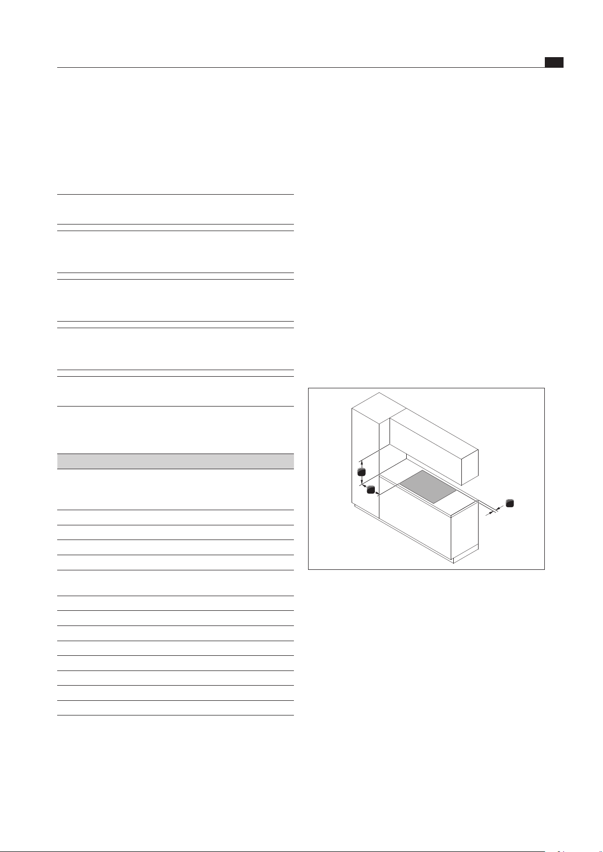
6.3.1 Safety distances
Maintain the following safety distances:
1
3
2
Fig. 6.1 Recommended minimum clearances
[1] Minimum distance of 50 mm at the back between worktop
cut-out and the rear edge of the worktop.
[2] Minimum distance of 300 mm from the left and right of the
worktop cut-out to the adjacent cabinet or wall.
[3] Minimum distance of 600 mm between the worktop and the
wall unit. A minimum clearance of 1000 m is recommended
for ergonomic reasons.
6.3.2 Work surface and kitchen units
Create the worktop cut-out taking the specified cut-out
dimensions into account.
Make sure that the cutting surfaces of the worktops
are properly sealed.
Observe the instructions provided by the worktop
manufacturer.
Cross bars on the unit in the area of the worktop
cut-out may need to be removed.
EN
20
Assembly
www.bora.com
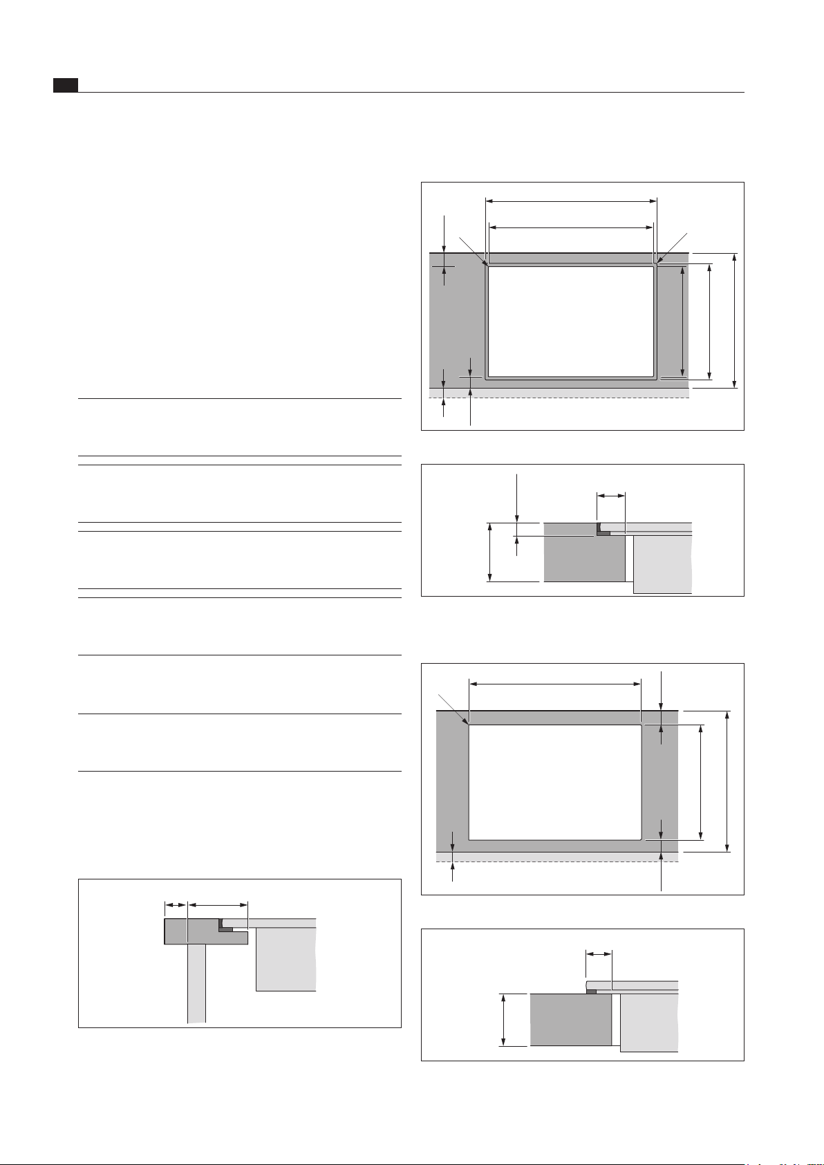
Flush installation
x
764 ±2
735 ±2
519 ±2
≤ R5
≤ R5
≥ 50
≥ 50
490 ±2
≥ 600
Fig. 6.3 Dimensions of cut-out for ush installation
6,5 +0,5
14,5
10 - 50
Fig. 6.4 Dimensions of groove for ush installation
Surface installation
x
735 ±2
≤ R5
≥ 50 ≥ 50
490 ±2
≥ 600
Fig. 6.5 Dimensions of cut-out for surface installation
12,5
10 – 50
Fig. 6.6 Dimension of support for surface installation
A false floor underneath the cooktop with integrated
cooktop extractor is not needed.
The drawers and/or shelves in the floor unit must be
removable.
A return flow aperture > 500 cm
2
is required in the
kitchen units for recirculation appliances (e.g. by
shortening the plinth boards or using suitable slatted
plinths).
The power socket is underneath the device on the front.
6.3.3 Cooktop air intake
The components in the cooktop which generate heat are
automatically cooled. The warm air is extracted by fans
(cold air flow).
INFO In order to retain the full functionality of the
cooktop in the long term, there must be suffi-
cient ventilation underneath the cooktop.
INFO The performance of the cooktop is impaired or
the cooktop overheats if the warm air below
the cooktop cannot escape.
INFO If the cooktop overheats, performance is re-
duced or the cooktop switches off completely
(see Overheating protection).
INFO For sufficient air intake, an opening cross-sec-
tion in the kitchen units of at least 50 cm
2
is
recommended.
Ensure there is sufficient ventilation underneath the
cooktop.
INFO If there are plans for a cable protection floor
(false floor) below the device, this must not
impede the ventilation.
6.4 Dimensions of cut-out for
cooktop
Worktop overhang
≥50x
Fig. 6.2 Worktop overhang
Please note the worktop overhang x when creating
the worktop cut-out. Applies to flush installation and
surface mounting.
EN
21
Assembly
www.bora.com
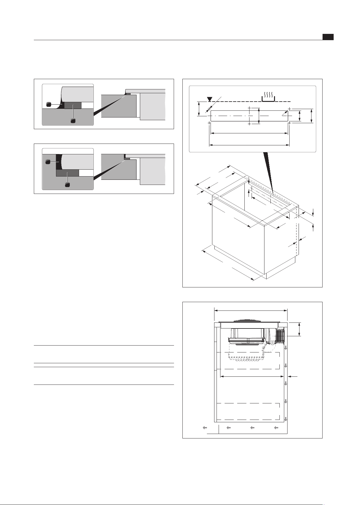
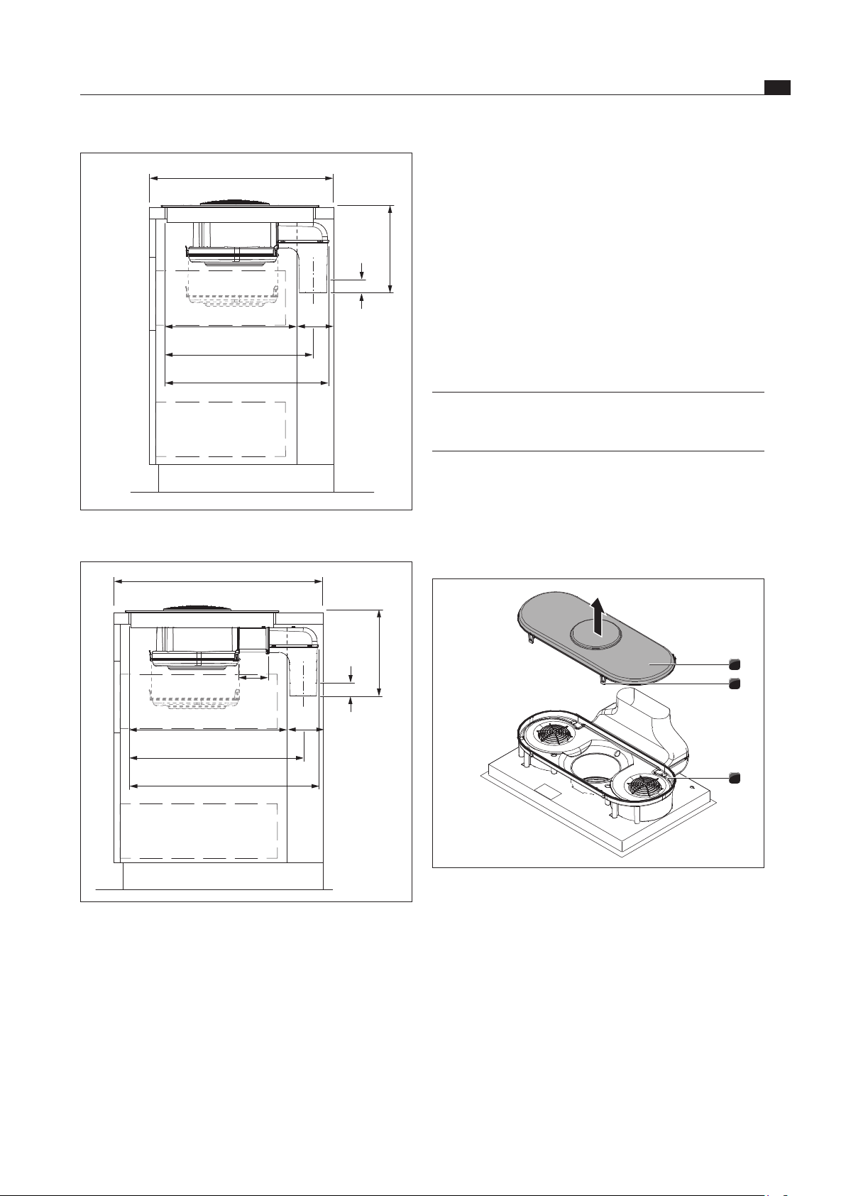
Installation dimensions
735
510 - 570
>800
650
>50
119
>25
90
490
>600
90
117
650
675
< R15
133
119
6x Ø5mm
Fig. 6.9 Dimensions of furniture, recirculated air
> 25
510 - 570
119
> 600
Fig. 6.10 Installation dimensions for recirculated air, worktop
depth 600 mm
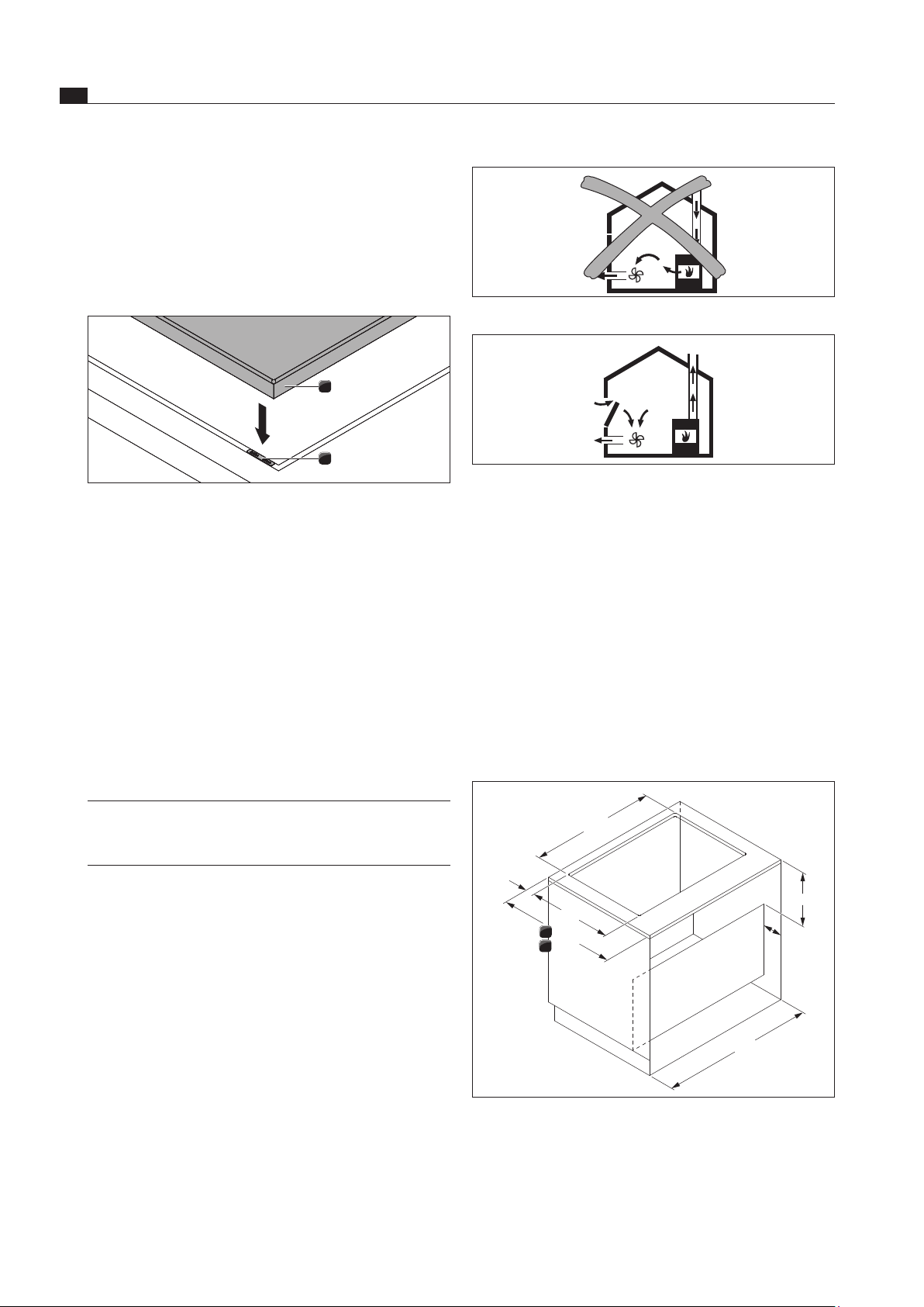
6.5 Attaching the sealing tape
2
1
Fig. 6.7 Sealing tape, surface installation
1
2
Fig. 6.8 Sealing tape, ush installation
[1] Black heat-resistant silicone sealing compound
[2] Sealing tape
With surface installation, attach the included seal-
ing tape [2] on the underside of the cooktop before
installing it. Do not leave any gaps.
With flush installation, attach the sealing tape [2] to
the horizontal cutting edge in the worktop cut-out,
even if you seal the cooktop with a silicone sealing
compound [1] or similar.
Note down the type designation and build number of
the cooktop (FD number) on the back of this manual.
Both designations can be found on the nameplate on
the underside of this cooktop.
6.6 Installing the air recirculation
version (BIU)
INFO There must be a minimum clearance of 25 mm
for the vertical return flow aperture.
INFO There must be a return flow aperture of at least
500 cm
2
.
When the cooktop extractor is exclusively used in
recirculated air mode, it is possible to operate it with an
open furnace without any additional safety measures
being required.
EN
22
Assembly
www.bora.com
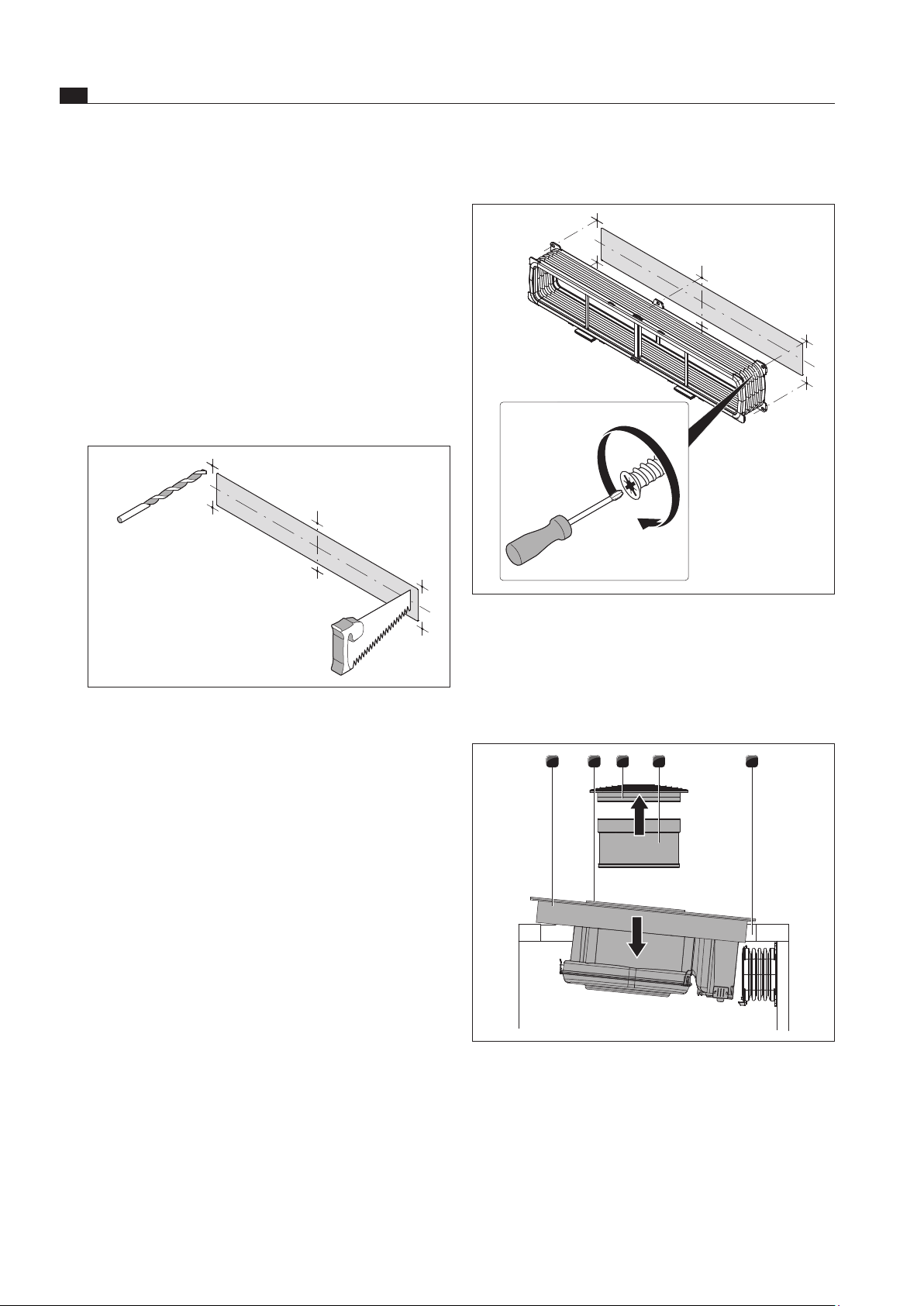
Screwing on the flexible duct
Fig. 6.12 Flexible duct with 6 EURO screws 6.3x10 mm
Using a screwdriver (not a cordless drill) screw the
flexible duct into the rear wall of the furniture until
hand-tight.
Inserting the cooktop
54321
Fig. 6.13 Insert the cooktop at an angle
[1] Cooktop
[2] Suction opening
[3] Air inlet nozzle
[4] Stainless steel grease filter
[5] Worktop cut-out
Before inserting, remove the air inlet nozzle [3] and the
stainless steel grease filter [4].
Use the suction opening [2] as a handle when inserting.
The floor unit must have a continuous rear wall so that
the returned recirculated air is not directed into the
front furniture body compartment.
There must be a cut-out in the rear wall.
A minimum clearance of 25 mm between the rear wall of
the furniture body and an adjacent piece of furniture or
room wall must be observed for the return flow aperture.
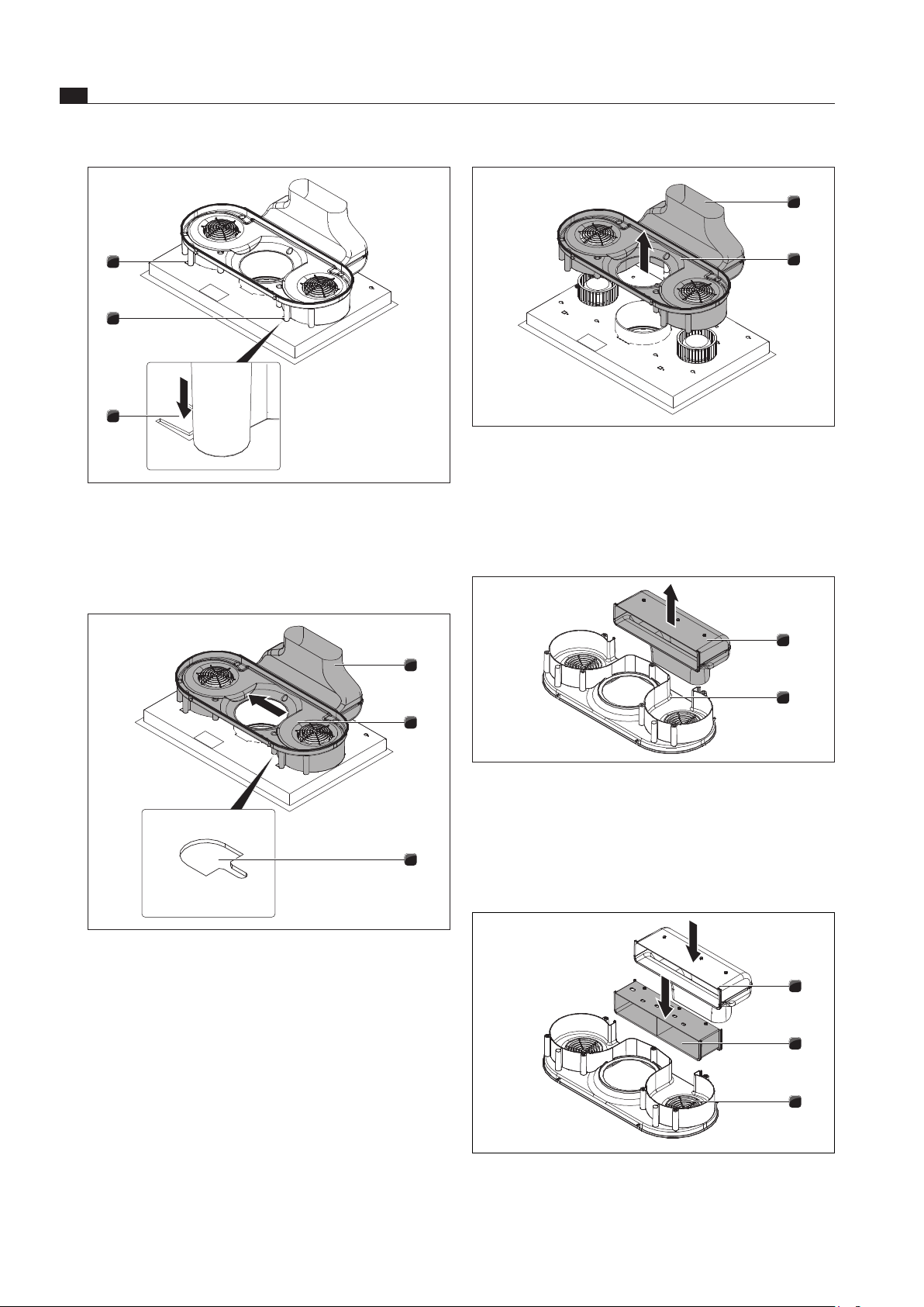
Preparing the rear wall of the furniture
Adjust the rear wall according to the required installa-
tion dimensions.
You may need to move the rear wall.
Where necessary, extend the height of the rear wall so
that the furniture body is closed to the front.
6 x ø5
Fig. 6.11 Cut-out and connection bores
Using the included drilling template, draw the return
flow aperture and the connection bores in the middle
of the cooktop based on the installation dimensions.
Saw out the return flow aperture.
Rough-drill the connection bores.
Decrease the height of the skirting boards or create
corresponding apertures in the base.
EN
23
Assembly
www.bora.com
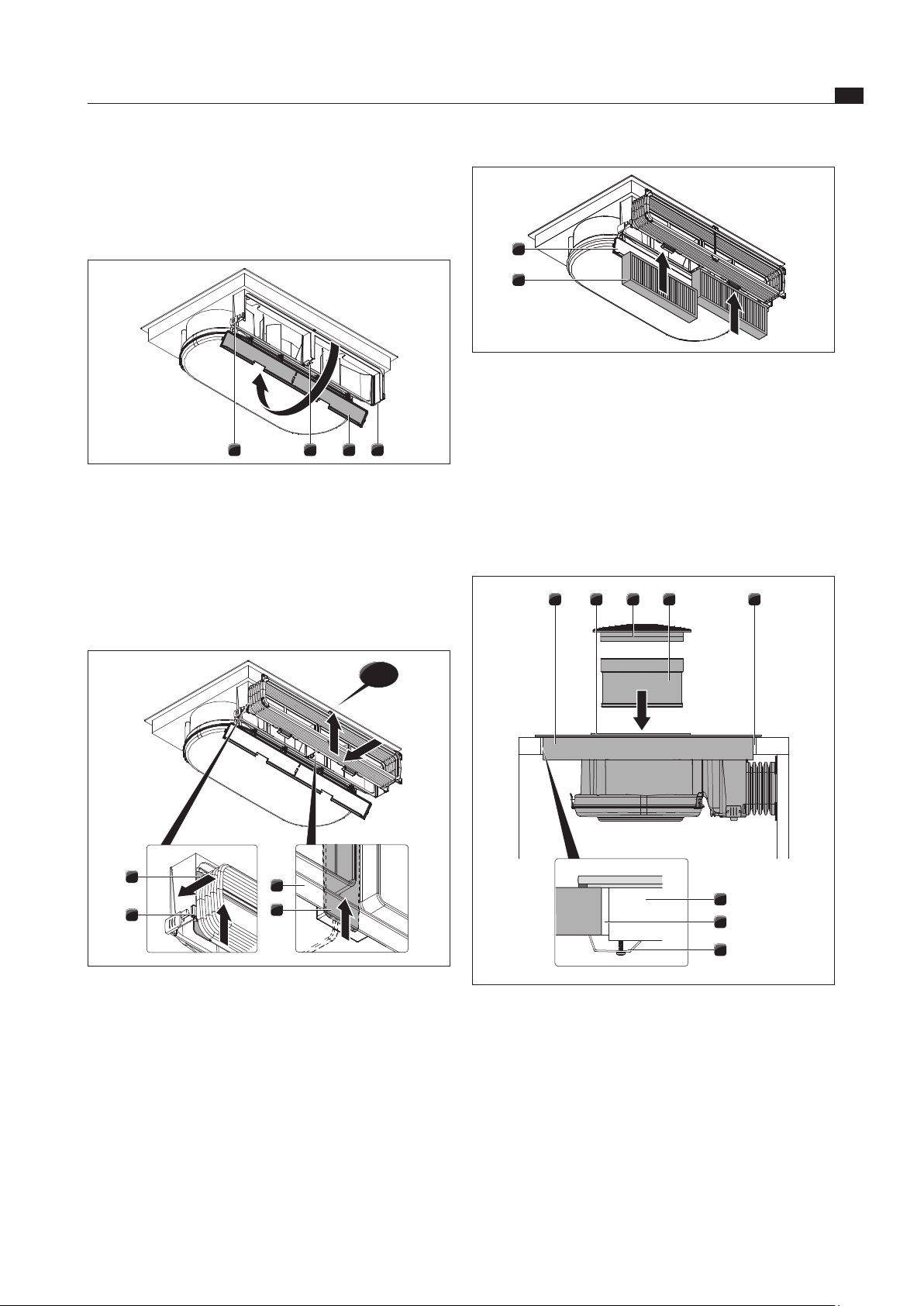
1
2
Fig. 6.16 Inserting the activated charcoal lter
[1] Housing cover of the activated charcoal filter
[2] Activated charcoal filter
Remove the packaging from the activated charcoal
filters.
Insert the two activated charcoal filters [2] from below.
Note the flow direction of the filter. This is indicated by
an arrow.
Close the cover to the housing [1].
54321
6
5
1
Fig. 6.17 Securing the cooktop in the middle
[1] Cooktop
[2] Suction opening
[3] Air inlet nozzle
[4] Stainless steel grease filter
[5] Worktop cut-out
[6] Mounting bracket
Lift the cooktop [1] diagonally into the worktop cut-out [5]
Place the cooktop [1] in the centre of the worktop cut-
out [5].
Align the cooktop precisely.
12 31
Fig. 6.14 Opening the housing cover
[1] Outer locks
[2] Middle lock
[3] Housing of the activated charcoal filter
Fold down the cover of the activated charcoal filter
housing [3] from below by opening the two outer locks
[1] and the middle lock [2].
click
2
4
3
1
Fig. 6.15 Hooking in the frame of the exible duct
[1] Position shackles
[2] Retaining groove on the activated charcoal filter housing
[3] Flexible duct frame
[4] Bottom lock
Hang the frame of the flexible duct into the retaining
groove on the activated charcoal filter housing [2].
Make sure that the two lateral position shackles [1] are
in the guide.
Slide the frame [3] up until the bottom lock [4] and the
upper lock engage in the middle.
Make sure that the frame is fitted all around in the
groove of the activated charcoal filter housing.
EN
24
Assembly
www.bora.com
Fig. 6.19 Incorrect exhaust air system installation
Fig. 6.20 Correct exhaust air system installation
When running the cooktop extractor in the room in
which a fireplace is installed, make sure that
the maximum underpressure is 4 Pa (4 x 10⁻⁵ bar),
a safety-related device (e.g. window contact switch,
minimum pressure controller) ensuring that a
sufficient supply of fresh air is guaranteed must
always be used,
the exhaust air may not be ducted into a chimney
that is used for exhaust gases of devices operated
with gas or other combustibles,
the installation has been inspected and signed off
by a qualified professional (e.g. chimneysweep).
Installation dimensions
735
490
>50
>800
320
110
b
a
600
700
Fig. 6.21 Furniture dimensions, exhaust air
[a] Worktop depth from 600 mm
[b] Worktop depth from 700 mm
For surface installation
Make sure that the sealing tape of the cooktop is
resting on the worktop.
For flush installation
Make sure that the sealing tape of the cooktop is
sealed well all the way round.
1
2
Fig. 6.18 Height adjustment plates
[1] Cooktop
[2] Height adjustment plates
If necessary insert height adjustment plates [2].
Fasten the cooktop using the mounting brackets [6] at
the worktop.
Afterwards, insert the stainless steel grease filter [4]
and air inlet nozzle [3].
Seal the surrounding gap with a black heat-resistant
silicone sealing compound.
6.7 Installing exhaust air duct variant
(BIA)
INFO National and regional laws and regulations
must be followed when executing the exhaust
air duct. Sufficient intake air must be provided.
6.7.1 Using the cooktop extractor with a
fireplace which does not depend on
room air
Fireplaces depending on room air (e.g. gas, oil, wood
or coal-fired heaters, continuous-flow water heaters,
instantaneous water heaters) draw in air from the room in
which they are installed and discharge the exhaust fumes
to the outside via an exhaust system (e.g. chimney).
When the cooktop extractor is used for exhaust air
operation, it draws in air from the room it is installed in
and from neighbouring rooms. If there is insufficient air, an
underpressure will occur. Toxic gases could be drawn out
of the chimney or extraction duct and back into the room.
EN
25
Assembly
www.bora.com
The maximum exhaust air duct length is 6 m.
Planning information for the installation of the
exhaust air ducts are provided in the BORA ventilation
instructions.
Preparing the rear wall of the furniture
Before carrying out the installation at the floor unit,
check the required installation dimensions for the
device and the planned duct system.
Adjust the position of the rear wall according to the
required installation dimensions as necessary.
Extending the exhaust air duct
INFO The exhaust air duct can optionally be
extended by 100 mm to the rear using the
supplied horizontal extension BLAVH1.
Remove the air inlet nozzle and stainless steel grease
filter.
With the glass ceramic panel facing downwards, place
the cooktop onto a clean and protective surface (e.g.
cardboard, packaging material) to prevent damage to
the glass ceramic panel.
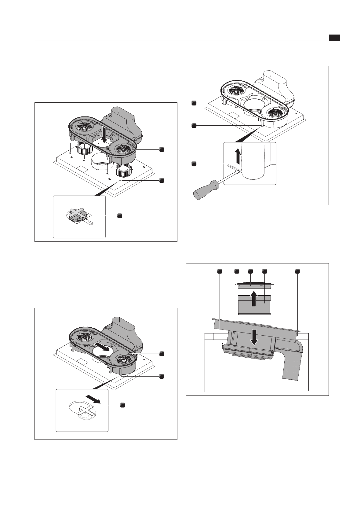
3
2
1
Fig. 6.24 Removing the housing base
[1] Housing base
[2] Locks
[3] Air guiding housing
Open the 4 locks [2].
Remove the housing base [1] from the air guiding
housing [3].
> 600
< 430
480
535
105
290
40
Fig. 6.22 Installation dimensions for exhaust air, worktop depth
600 mm
> 700
< 530
580
635
105
290
40
100
Fig. 6.23 Installation dimensions for exhaust air, worktop depth
700 mm
Installation conditions
The rear wall of the floor unit must be adjusted for the
exhaust air duct.
A minimum clearance of 110 mm between the rear
wall of the furniture body and an adjacent piece of
furniture or wall must be observed for the duct.
The exhaust air must be directed to the outside in
appropriate exhaust air ducts.
The minimum cross-section of the exhaust air ducts
must be 176 cm
2
. This equates to a cylindrical tube
with a diameter of 150 mm.
EN
26
Assembly
www.bora.com
2
1
Fig. 6.27 Removing the air guiding housing
[1] Exhaust air arc
[2] Air guiding housing
Remove the air guiding housing [2] with exhaust air arc
[1] upwards.
2
1
Fig. 6.28 Removing the exhaust air arc
[1] Exhaust air arc
[2] Air guiding housing
Move the exhaust air arc [1] from the air guiding
housing [2] upwards.
3
2
1
Fig. 6.29 Inserting the extension for exhaust air duct
[1] Exhaust air arc
[2] Extension for exhaust air duct
[3] Air guiding housing
1
1
1
Fig. 6.25 Releasing the position lock
[1] Shackles for position lock
Using a screwdriver, press the shackles [1] downwards
left and right to release the position lock.
3
2
1
Fig. 6.26 Moving the air guiding housing
[1] Exhaust air arc
[2] Air guiding housing
[3] Support opening
Move the air guiding housing [2] together with the
exhaust air arc [1] as far as the left-hand edge of the
support opening [3].
EN
27
Assembly
www.bora.com
1
1
1
Fig. 6.32 Position lock
[1] Shackles for transport and position lock
Press the two shackles [1] for the position lock upwards.
Lift the cooktop with integrated cooktop extractor.
Turn the glass ceramic panel upwards.
54321
Fig. 6.33 Inserting the cooktop
[1] Cooktop
[2] Suction opening
[3] Air inlet nozzle
[4] Stainless steel grease filter
[5] Worktop cut-out
Use the suction opening [2] as a handle during insertion.
Reach into the suction opening [2].
Insert the cooktop centrally into the provided worktop
cut-out [5].
Align the cooktop precisely.
Insert the extension for the exhaust air duct [2] into
the groove of the air guiding housing [3].
Insert the exhaust air arc [1] into the groove of the
extension for the exhaust air duct [2].
2
2
1
Fig. 6.30 Inserting the airow assembly on the cooktop base
[1] Airflow assembly
[2] Openings
Position the airflow assembly [1] at the cooktop base
in such a way that all retaining hooks are in the
openings [2].
2
2
1
Fig. 6.31 Engaging the airow assembly
[1] Airflow assembly
[2] Openings
Now move the airflow assembly [1] to the right until it
engages fully into the slot of the opening [2].
EN
28
Assembly
www.bora.com
Connect the exhaust air duct [7] installed on-site to the
exhaust air arc [6].
Seal the duct connection so that it is airtight using
adhesive sealing tape UDB1.
Fasten the cooktop using the mounting brackets [8] at
the worktop.
Afterwards, insert the stainless steel grease filter [4]
and air inlet nozzle [3].
Seal the surrounding gap with a black heat-resistant
silicone sealing compound.
6.8 Establishing the power
connection
Observe all safety and warning information (see Safety
chapter).
Observe all national and regional laws and regulations
as well as the supplementary regulations of the local
utility companies.
INFO The power connection must only be
implemented by a certified engineer. He/she
also assumes responsibility for the proper
installation and commissioning.
INFO Connection via plug-in contacts, e.g. plugs with
earthing contacts, are not allowed.
INFO The device complies with IEC 61000-3-12
Switch off the main switch/automatic circuit breaker
before connecting the cooktop.
Protect the main switch/automatic circuit breaker
from being switched on without permission.
Make sure the device is not energised.
Only connect the cooktop using a permanent
connection to a type H 05 VV-F power supply line
with appropriate minimum cross section (s. Tab. Fuse
protection and minimum cross section).
Connection Fuse protection Minimum
cross-section
Three-phase-connection 3 x 16 A 2.5 mm
2
Two-phase-connection 2 x 16 A 2.5 mm
2
One-phase-connection 1 x 32 A 4 mm
2
Tab. 6.2 Fuse protection and minimum cross section
For surface installation
Make sure that the sealing tape is resting on the
worktop.
For flush installation
Make sure that the sealing tape of the cooktop is
sealed well all the way round.
1
2
Fig. 6.34 Height adjustment plates
[1] Cooktop
[2] Height adjustment plates
If necessary insert height adjustment plates [2].
54321
8
5
7
6
1
Fig. 6.35 Connecting the exhaust air duct + secure
[1] Cooktop
[2] Suction opening
[3] Air inlet nozzle
[4] Stainless steel grease filter
[5] Worktop cut-out
[6] Exhaust air arc
[7] Exhaust air duct
[8] Mounting bracket
EN
29
Assembly
www.bora.com
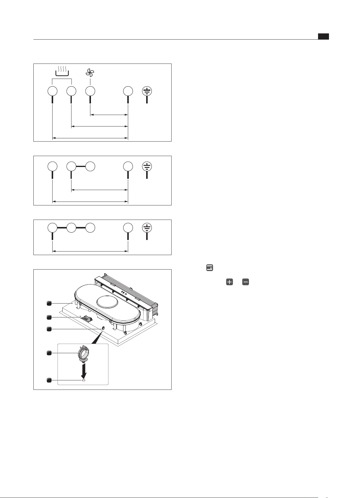
1
L1 L2
L3
2 3 4
N
PE
220 - 240 V~
220 - 240 V~
220 - 240 V~
Fig. 6.36 Connection diagram 3-phase connection
1
L1 L2
2 3 4
N
PE
220 - 240 V~
220 - 240 V~
Fig. 6.37 Connection diagram 2-phase connection
1
L1
2 3 4
N
PE
220 - 240 V~
Fig. 6.38 Connection diagram 1-phase connection
3
3
1
1
2
Fig. 6.39 Electrical connections of the cooktop
[1] Bore holes
[2] Power supply
[3] Cable mounting clip
Based on the relevant connection diagram (see
Figs. Connection diagram), connect the power supply
line to the power connection [2] on the cooktop with
integrated cooktop extractor.
For one- or two-phase-connections install the relevant
contacts with the BKAS connector clip (included in the
scope of delivery).
Fasten the cable mounting clips [3] in the designated
bore holes (1) either on the left or right hand side for
the cable routing to the rear.
Make sure that the cable is not clamped or damaged
and cannot touch any hot parts of the cooktop.
Verify that the installation was done correctly.
Switch on the main switch/automatic circuit breaker.
Put the cooktop extractor into operation (see the
Operation chapter).
Check all the functions are working correctly.
Device power management
(total power reduction)
The total power of the device can be reduced to 4.4
KW for initial commissioning, if the required electrical
power cannot be provided at the site of installation.
The connection must always be equipped with a fuse
protection of at least 20 A.
Programming the device power management
For the programming process, the device must not be
switched on and the childproofing feature must not be
active. Program the cooktop within 2 minutes after the
cooktop is supplied with power.
For programming, press all 4 cooking zone selection
buttons at the same time for 3 seconds.
The display will show 7.4 (factory setting).
By pressing the or button, set the reduced
total power consumption to 4.4.
To save your settings, press all 4 cooking zone selec-
tion buttons at the same time for 3 seconds until an
acoustic signal sounds.
The acoustic signal indicates that the setting is saved
and the cooktop switches itself off.
If the cooktop is switched on again, it is ready for use.
6.9 Handover to user
Once installation is done:
Explain the important functions to the user.
Explain all safety-relevant aspects of operation and
handling to the user.
Provide the user with the accessories and operating
and installation instructions to be kept in a safe place.
EN
30
Operation
www.bora.com
7 Operation
Observe all safety and warning information during
operation (see Safety chapter).
INFO The integrated cooktop extractor must not be
used with other cooktops.
INFO The cooktop should only be operated when the
stainless steel grease filter and air inlet nozzle
are installed.
7.1 Switching cooktop on/off
Switching on
Press to switch on the cooktop.
The power level
0
is displayed in the cooking zone
indicators.
Switching off
INFO Use the operating panel to switch off the
cooking zone after use. Do not rely on the pan
size recognition.
Press to switch off the cooktop.
Pay attention to the residual heat display
(see Device Description chapter).
7.1.1 Switching on the cooking zone
Press the cooking zone button (e.g. ) of the desired
cooking zone.
The
0
in the cooking zone indicator lights up more
brightly. The cooking zone indicator light lights up.
7.1.2 Adjusting the power level
Press to set power level
5
or
press to set power level
9
.
7.1.3 Changing the power level
Press the cooking zone button (e.g. ) of the desired
cooking zone.
The cooking zone indicator lights up more brightly.
Press or until the required power level is shown
in the cooking zone indicator.
7.1.4 Switching on the power setting
INFO Only the two front cooking zones are equipped
with a power-enhancing power setting.
Press the cooking zone button (e.g. ) of the desired
cooking zone.
Continue pressing until power level
P
is displayed in
the cooking zone indicator.
After 5 minutes, the cooking zone is automatically
switched to power level
9
.
If one cooking zone is operated with the
P
power set-
ting, then the operation of the second cooking zone on
this side is possible at a maximum of power level
5
.
If power level
5
is increased, the
P
power setting is
switched off.
7.1.5 Switching the power setting off early
Press the cooking zone button (e.g. ) of the desired
cooking zone. The indicator will appear brighter.
Continue pressing until the lower power level that
you want is displayed.
7.1.6 Switching off the cooking zone
Press the cooking zone button (e.g. ) of the desired
cooking zone.
Continue pressing or until the cooking zone
indicator displays power level
0
.
The display will show a
0
for a few seconds.
7.1.7 Pay attention to the residual heat
display
After switching it off, the cooking zone remains hot.
H
is displayed in the cooking zone indicator (residual heat
indicator). The cooking zone indicator will go out after
sufficient time is left to cool down (temperature < 60 °C).
INFO While a
H
is displayed in the cooking zone
indicator (residual heat display), do not touch
the cooking zone or place any heat-sensitive
objects on top of it. Risk of burns and fire!
Pay attention to the residual heat indicator.
Make sure the hot hobs are not touched and no
objects are placed on it.
7.1.8 Using the timer function
Prerequisite
The cooktop must be switched on.
You can use 2 timer functions:
Short time (egg timer)
(the cooking zone is not automatically switched off)
Automatic cut-off (for automatic cutting off of a
cooking zone)
You can set a time range of between 1 and 99 minutes for
both timer functions.
INFO After the pre-set time has passed in the timer
display,
00
will be shown for a few seconds.
A signal tone will sound for a few seconds.
EN
31
Operation
www.bora.com
Switching the timer off early
Press the cooking zone button of the cooking zone for
which you wish to switch off the timer.
Press and simultaneously.
In the timer display, the set time is displayed and the
cooking zone indicator light flashes.
Press until the timer display shows
00
.
7.1.9 Activating/deactivating the child
safety lock
INFO If a cooking zone indicator alternately shows
L
and
H
, this means the cooking zone is still hot.
Activating the child safety lock
Prerequisites:
The cooktop is switched on.
All cooking zones are switched off.
Within 10 seconds of switching it on, press sensor
buttons and simultaneously before pressing
sensor button one more time.
L
is displayed in all cooking zone indicators. The child
safety lock is activated.
Deactivating the child safety lock for a
cooking session
INFO If a cooking zone indicator alternately shows
0
and
H
, this means the cooking zone is still hot.
Press sensor buttons and simultaneously. The
power level
0
is displayed in all cooking zone indicators
and the cooking zone indicator lights flash.
The power level you require can now be set for each
cooking zone.
After the cooktop has been switched off, the child safety
lock is activated again.
Deactivating the child safety lock
INFO If a cooking zone indicator alternately shows
0
and
H
, this means the cooking zone is still hot.
Prerequisites:
The cooktop is switched on.
Press sensor buttons and simultaneously and
then one more time.
All cooking zone indicators display power level
0
. The
child safety lock is deactivated.
INFO If you first press , 1 minute is pre-set as the
start time.
If you first press , 30 minutes are pre-set as
the start time.
Switching off the timer signal tone
Press any sensor button on the operating panel to end
the signal tone prematurely.
Setting the short time (egg timer)
Press and simultaneously.
In the timer display
00
will appear for a few seconds on
both rear cooking zone indicators.
Press or to set the required time.
Setting the automatic cut-off (timer)
You can set an automatic cut-off for every cooking zone.
INFO The cooking zone control light indicates
whether the automatic cut-off is activated. The
cooking zone indicator light lights up until the
cooking zone is switched off after the pre-set
time has passed.
INFO If several cooking zones are activated with an
automatic cut-off, the cooking zone indicator
light with the lowest timer value will light up
provided that a cooking zone was not selected.
Prerequisite
A cooking zone has been selected.
A power level was set.
Press and simultaneously.
In the time display
00
will appear for a few seconds on
both rear cooking zone indicators.
Press or to set the required time.
After the last input, the set time will be displayed in the
timer display for a few seconds.
Changing the timer settings
Press the cooking zone button for the cooking zone,
for which you wish to change the automatic cut-off.
Press and simultaneously.
In the timer display, the set time is displayed and the
cooking zone indicator light flashes.
Press or to set the required time.
If several timers are active
Continue pressing and simultaneously until
the indicator light for the desired cooking zone starts
flashing.
The cooking zone control lights are controlled in a
clockwise order for which a timer was activated,
beginning with the short time (egg timer).
Press or to change the set time.
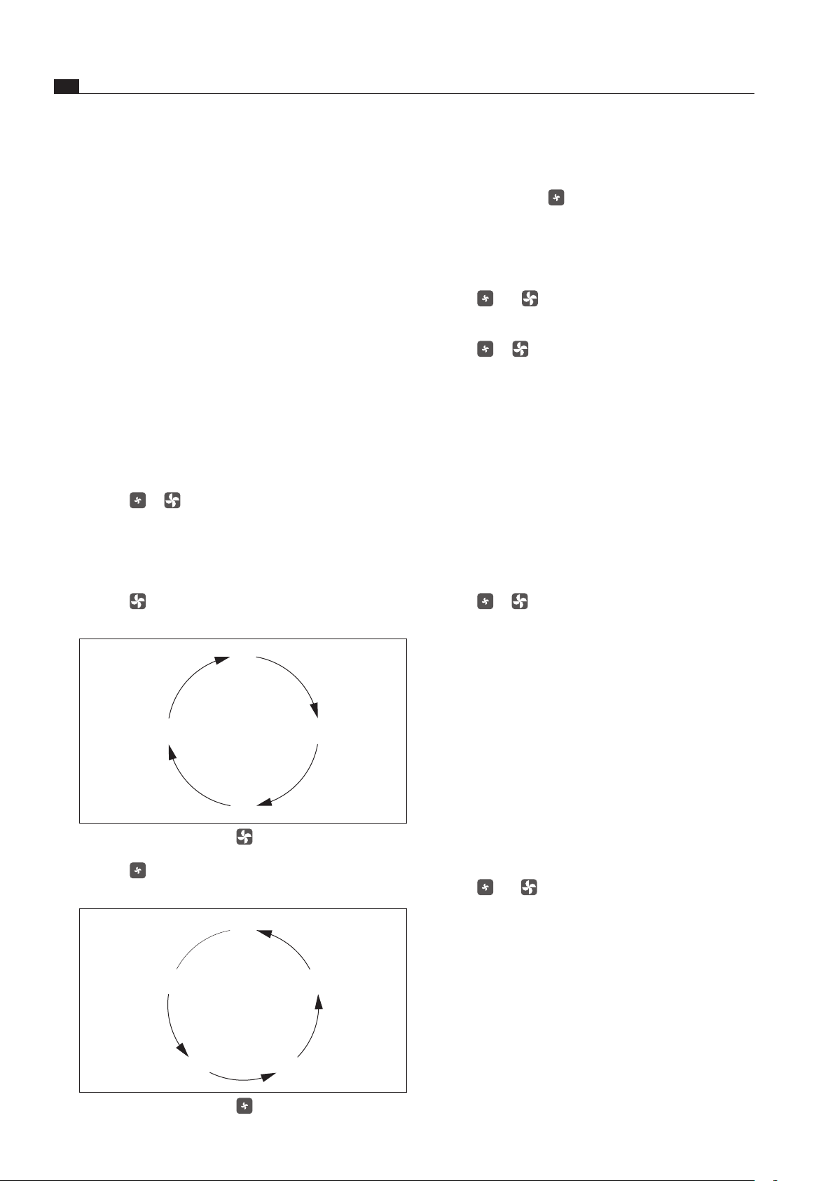
EN
32
Operation
www.bora.com
7.2.3 Switching on the delayed automatic
after-run
Continue pressing until power level
n
is displayed
for automatic after-run.
The fan runs in level 1 and switches off automatically
after 10 minutes.
7.2.4 Switching off the cooktop extractor
Press and simultaneously until the fan level
indicator
0
is displayed.
or
Press or several times until the fan level
indicator
0
is displayed.
When the fan level indicator displays
0
, the cooktop
extractor is switched off automatically after a few seconds.
7.3 Pay attention to the filter service
display
If the fan level indicator displays
F
(F = filter service
indicator), this means the activated charcoal filter is used
up (for recirculated air only) and the stainless steel grease
filter needs an overhaul.
If you do not wish to do the filter change yet, e.g. if you
only cook occasionally:
Press or to go into the normal operating mode.
0
is shown in the fan level indicator.
Changing the filter
Switch off the cooktop with integrated cooktop extractor.
Observe all warnings that are described in the
Cleaning chapter.
Replace the activated charcoal filter.
Clean the stainless steel grease filter, the air inlet nozzle,
the air guiding housing and the housing base.
Resetting the filter service display
If the activated charcoal filter was replaced (only for recircu-
lated air) and the stainless steel grease filter was cleaned, it
will be necessary to reset the filter service display.
Switch on the cooktop with integrated cooktop extractor.
The fan level indicator displays
F
.
Press and simultaneously for at least three
seconds until a
0
flashes in the fan level indicator.
After a few seconds,
0
will be displayed permanently.
The filter service display has been reset.
7.2 Operating the cooktop extractor
Prerequisite:
The cooktop with integrated cooktop extractor is
switched on.
Recommendations for an efficient vapour extraction:
Make sure to always use a lid for pots that are
particularly high. This ensures effective vapour
extraction. It also reduces power consumption.
Only operate the cooktop extractor at the minimum
power level required for an effective vapour extraction.
This way, you can improve the performance of the
odour filters during air circulation operation.
Only operate the hob at the minimum power level
required for cooking. This reduces the cooking vapours
and power consumption.
Avoid strong drafts.
7.2.1 Switching on the cooktop extractor
Press or to switch on the cooktop extractor.
0
is shown in the fan level indicator. If no further
input is made, the cooktop extractor will switch off
automatically a few seconds afterwards.
7.2.2 Setting the fan level
Press to increase the fan level.
The following fan level sequence is run through:
Fig. 7.1 Fan level sequence
Press to reduce the fan level. The following fan level
sequence is run through:
Fig. 7.2 Fan level sequence

EN
33
Operation
www.bora.com
7.4 Saving energy
Follow all of the energy-saving tips to use the cooktop
with integrated cooktop extractor in an energy-efficient
manner.
When purchasing cookware, pay attention to the
diameter of the base. Usually the upper diameter of the
pot is given. The diameter of the base is often smaller.
Use pressure cookers. Due to the closed cooking
chamber and the overpressure, pressure cookers save
the most time and energy. The short cooking time
helps preserve vitamins.
Make sure there is sufficient liquid in the pressure
cooker. An empty pot which is still being heated can
lead to overheating. The cooking zone and the pot may
be damaged by overheating.
If possible, always close cookware using a suitable lid.
Choose a suitable size of cookware commensurate
with the amount of food you are cooking. A big pot that
is barely filled requires a lot of energy.
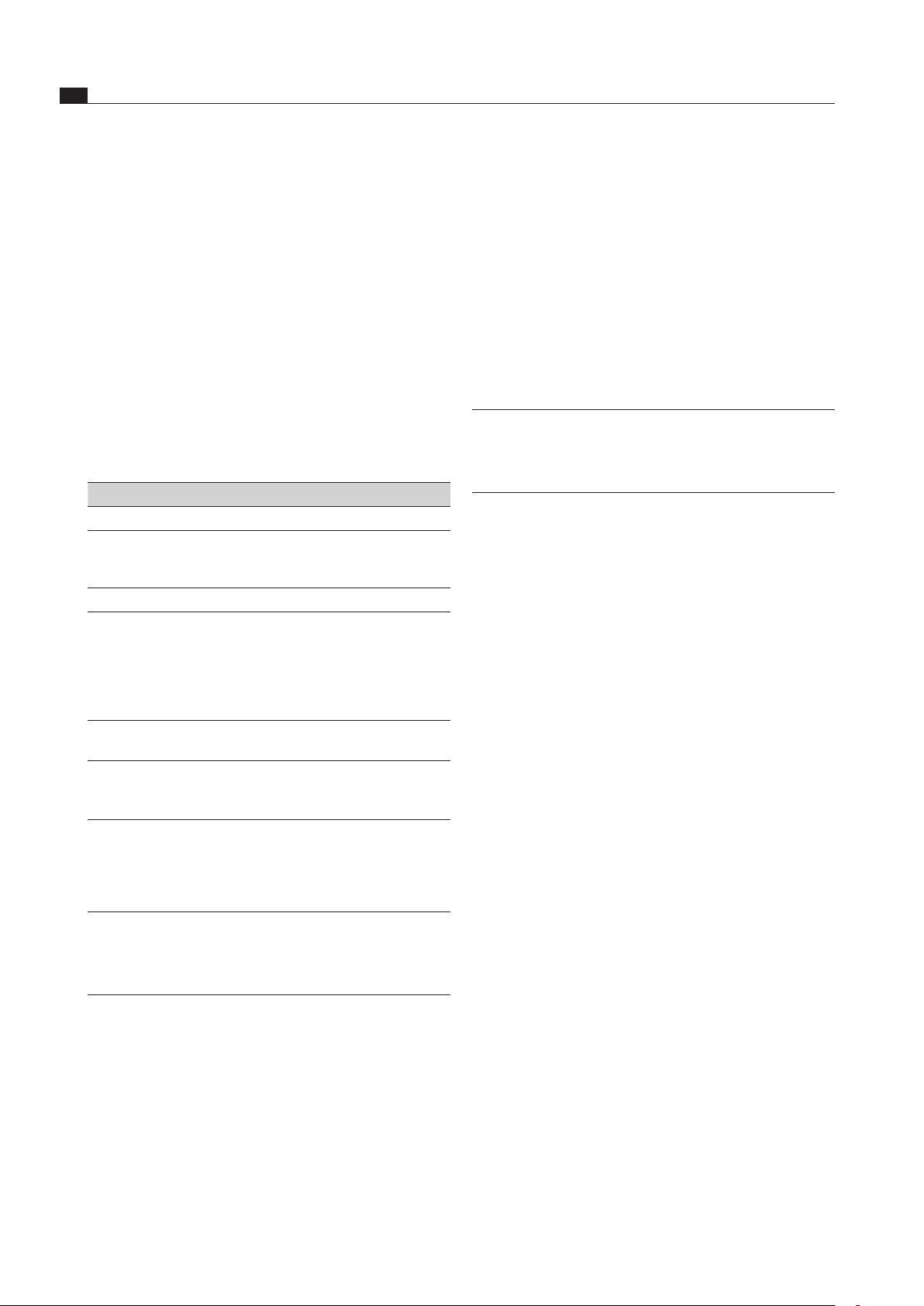
EN
34
Cleaning and maintenance
www.bora.com
8 Cleaning and
maintenance
Observe all safety and warning information
(see Safety chapter).
Follow the enclosed manufacturer’s information.
Make sure that the cooktop and cooktop extractor
have been switched off completely and have cooled
down prior to the planned cleaning and maintenance
work to prevent injury (see the Operation chapter).
Regular cleaning ensures the longevity of the product
and optimal functioning.
Adhere to the following cleaning and maintenance
cycles:
Component Cleaning cycle
Operating panel Immediately after every soiling
Cooktop Immediately after every soiling every week
thoroughly with standard commercially
available glass ceramic cleaners
Cooktop extractor Weekly
Air inlet nozzle and
stainless steel grease
filter
After every time you prepare very greasy
foods; at least weekly, when the fan
level indicator =
F
by hand or in the
dishwashing machine (at a max. 65 °C);
Only clean the stainless steel surfaces in
the polishing direction!
Air guiding housing Clean every 6 months or when replacing
the activated charcoal filter
Activated charcoal
filter (only for
recirculated air)
Replace after the build-up of odour, when
the extraction power has diminished or
the fan level indicator shows
F
Tab. 8.1 Cleaning cycles
8.1 Cleaning agents
INFO Due to the use of aggressive cleaning agents
and abrasion caused by the pot bases the
surface will become damaged and dark stains
will occur.
You need a special glass ceramic panel scraper and
suitable cleaning agents to clean the cooktop.
Never use steam cleaners, abrasive sponges, scouring
pads, or chemically aggressive cleaning agents (e.g.
baking oven spray).
Make sure that the cleaning agent does not contain
any sand, soda, acids or chloride.
For air inlet nozzle and grease filter
Do not use any aggressive, acidic or alkaline cleaning
agents.
8.2 Maintaining the cooktop
Do not use the cooktop as a worktop or shelf.
Do not push or pull cookware across the cooktop.
Always lift pots and pans.
Keep the cooktop clean.
Remove any kind of soiling immediately.
Only use cookware which is suitable for glass ceramic
panels (see the Device description chapter)
8.3 Cleaning the cooktop
INFO When the cooktop extractor is switched on,
the air inlet nozzle is installed to ensure that no
small and light objects, such as cleaning wipes
made of fabrics or paper are sucked in.
Make sure that the cooktop is switched off (see
Operating chapter).
Wait until all cooking zones are cold.
Remove all coarse soiling and food residues from the
cooktop with a glass ceramic scraper.
Apply the cleaning agent onto the cold cooktop.
Rub the cleaning agent with a paper towel or a clean cloth.
Wipe off the cooktop while wet.
Rub the cooktop dry with a clean cloth.
When the cooktop is hot:
Immediately remove molten residues of plastic,
aluminium film, sugar or foods containing sugar with
a glass ceramic scraper from the hot cooking zone to
prevent burning them in.
Special soiling
Heavy soiling and stains (limescale stains, pearly
shimmering stains) are best to be removed if the
cooktop is still warm.
Soften dried dirt residues using a damp cloth.
Remove dirt residues with the glass ceramic scraper.
Always remove grains, crumbs or the like which fall
onto the cooktop during general cooking work right
away to prevent the surface from being scratched.
Coloured changes and shiny surfaces are not cooktop
damage. They do not impact on the function of the
cooktop and the stability of the glass ceramic.
Discolourations to the cooktop arise from residues which
are not removed and have been burnt in.
Glossy spots are caused by the abrasion of the pot base,
especially when using cooking utensils with aluminium
bases, or by unsuitable cleaning agents. They are very
hard to remove.
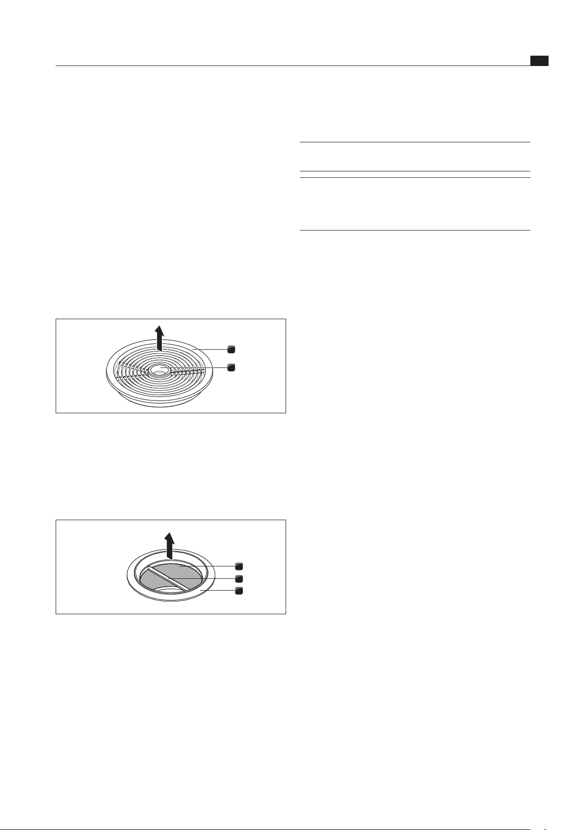
EN
35
Cleaning and maintenance
www.bora.com
8.4.2 Cleaning the air inlet nozzle and
stainless steel grease filter
INFO Clean the stainless steel surfaces in the
polishing direction only.
INFO If the stainless steel grease filter can no
longer be cleaned completely, this means the
stainless steel grease filter will need to be
replaced.
Manual cleaning
Use a degreasing cleaning agent.
Rinse the inlet nozzle and stainless steel grease filter
with hot water.
Use a soft brush to clean the inlet nozzle and stainless
steel grease filter.
After cleaning, rinse the inlet nozzle and stainless steel
grease filter well.
Cleaning in the dishwasher
Rinse the air inlet nozzle and the stainless steel grease
filter with a rinsing program at a maximum of 65 °C.
8.4.3 Installing stainless steel grease filter
and air inlet nozzle
Grab the stainless steel grease filter using the handle [2]
(Fig. 7.2)
Insert the stainless steel grease filter [1] into the
suction opening.
Make sure that the stainless steel grease filter rests
against the bottom housing base. A lock is not needed
and is not provided.
Reach into the access opening [2] of the inlet nozzle
with your hand (Fig. 7.1).
Insert the air inlet nozzle (Fig. 7.1; [1]) centrally into
the suction opening.
Press the air inlet nozzle upwards until it engages.
8.5 Cleaning the air guiding housing
Greasy deposits and limescale residues from the cooking
vapour can accumulate on the surface of the air guiding
housing. Regular, thorough cleaning (see Table 7.1) is
thus necessary.
The air guiding housing is on the underside of the cooktop
in the floor unit.
8.5.1 Opening the air guiding housing
Make sure that the cooktop and cooktop extractor are
switched off (see Operating chapter).
Wait until the fan display is
0
.
8.4 Cleaning the cooktop extractor
The air inlet nozzle and the stainless steel grease filter
absorb the greasy components of the kitchen vapour.
Make sure that the cooktop and cooktop extractor are
switched off (see Operating chapter).
Wait until the fan display is 0.
Clean the cooktop extractor in accordance with the
cleaning cycles (see Tab. 7.1).
Clean the surfaces of the exhaust air system using a
soft damp cloth, detergent or a mild window cleaning
agent.
Soften dried-on dirt residues using a damp cloth
(do not scratch!).
8.4.1 Removing the air inlet nozzle and
stainless steel grease filter
1
2
Fig. 8.1 Removing the air inlet nozzle
[1] Air inlet nozzle
[2] Access opening
Prerequisite: The fan level indicator indicates
0
.
Reach into the access opening [2] with your hand.
Remove the air inlet nozzle [1] out upwards.
3
2
1
Fig. 8.2 Removing the stainless steel grease lter
[1] Stainless steel grease filter
[2] Handle
[3] Suction opening
Grab the stainless steel grease filter using the
handle [2].
Pull the stainless steel grease filter [1] out of the
suction opening [3] upwards.
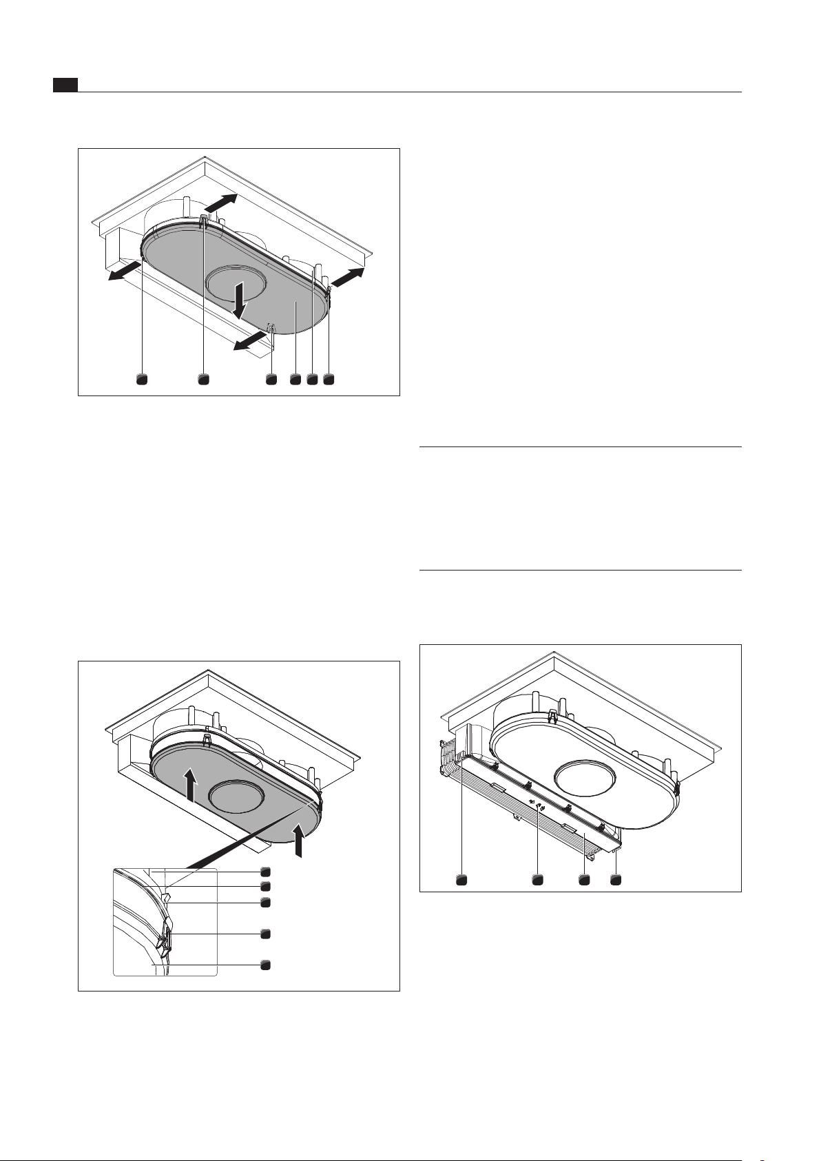
EN
36
Cleaning and maintenance
www.bora.com
Using both hands, position the housing base [5] so that
the position of the locking straps [4] on the housing base
match the position of the hooks [3] on the housing.
Insert the housing base at the sealing groove [2] of the
air guiding housing [1].
Press the housing base [5] upwards until the 4 locks
(2 front, 2 rear) engage into the hooks [3].
Check that all 4 locking straps [4] have correctly engaged.
8.6 Replacing the activated charcoal
filter
Two activated charcoal filters are used only when the
cooktop extractor is being operated in recirculated
air mode. The activated charcoal filter binds odorous
materials which arise during cooking.
INFO The activated charcoal filters must be replaced
when the fan level indicator indicates
F
(filter
service display).
BAKF activated charcoal filters can be
pur chased from your specialist.
You can also contact BORA on its homepage
http://www.bora.com.
Make sure that the cooktop and cooktop extractor are
switched off (see Chapter 6.1).
Wait until the fan display is
0
.
1
2 13
Fig. 8.5 Releasing the activated carbon lter housing lid
[1] Outer locks
[2] Middle lock
[3] Activated carbon filter housing cover
1 12 23 4
Fig. 8.3 Opening the air guiding housing
[1] Rear locks
[2] Front locks
[3] Housing base
[4] Air guiding housing
Hold the housing base with one hand [3].
Open both locks on the rear [1].
Open both front locks [2].
Remove the housing base [3].
Clean the air guiding housing [4] and the housing base
[3] with a mild cleaning agent.
8.5.2 Closing the air guiding housing
1
2
3
4
5
Fig. 8.4 Closing the air guiding housing
[1] Air guiding housing
[2] Sealing groove
[3] Hooks
[4] Locking strop
[5] Housing base
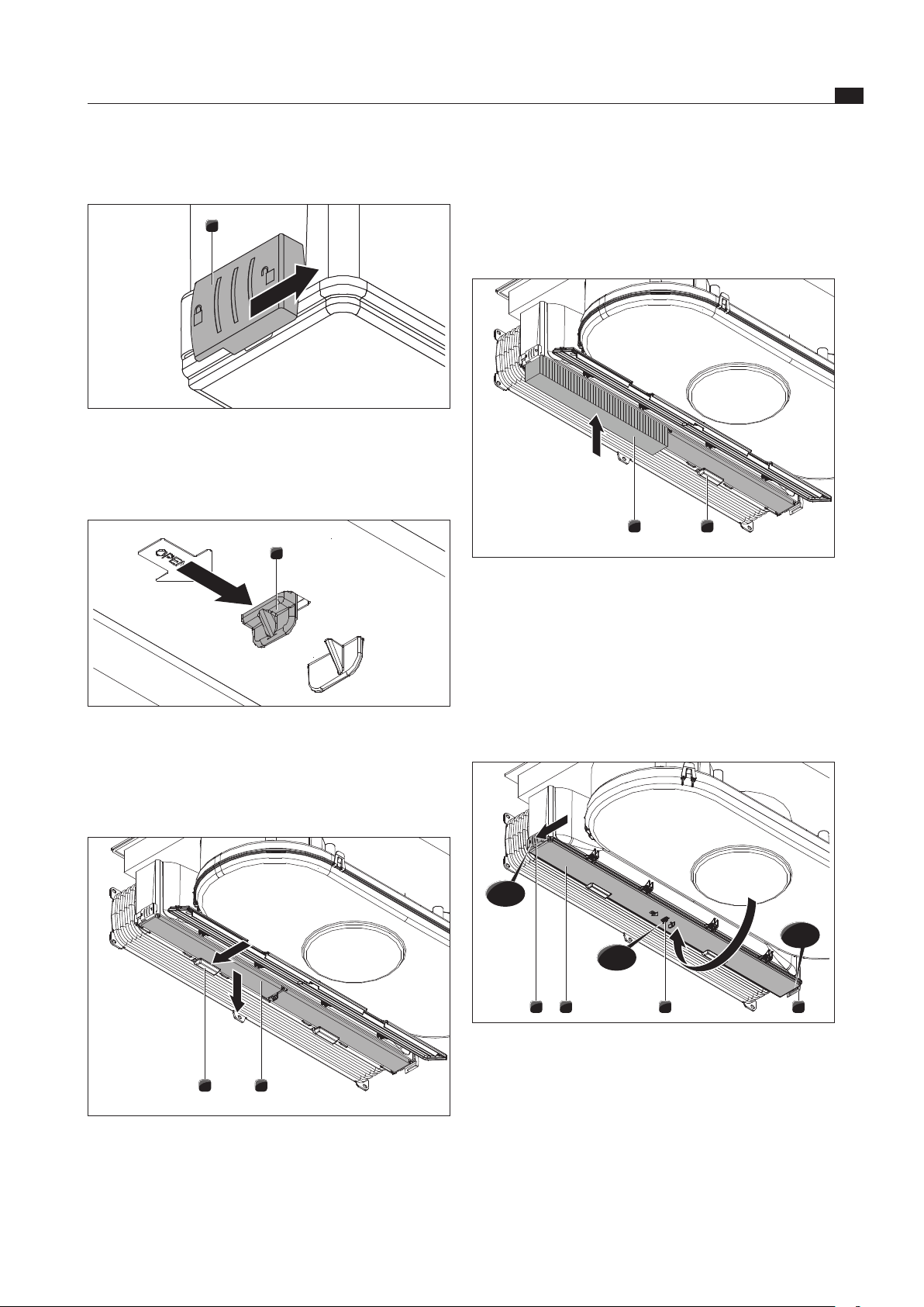
EN
37
Cleaning and maintenance
www.bora.com
Pull the activated charcoal filter down and out.
Dispose of the used activated charcoal filter in house-
hold waste.
Inserting the activated charcoal filter
1 2
Fig. 8.9 Inserting the activated charcoal lter
[1] Activated charcoal filter
[2] Filter retainer
Position the new activated charcoal filter [1] so that
the arrow points to the rear and is visible from below.
Slide the activated charcoal filter into the housing.
Push the activated charcoal filter upwards until the
filter retainer [2] engages.
1 3 12
click
click
click
Fig. 8.10 Closing the activated charcoal lter housing cover
[1] Outer locks
[2] Activated charcoal filter housing cover
[3] Middle lock
Fold up the activated charcoal filter housing cover [2].
Press the activated charcoal filter housing cover in the
centre until the middle lock [3] engages.
Press the activated charcoal filter housing cover on the
sides and close the outer locks [1] until they engage.
Removing the activated carbon filter
1
Fig. 8.6 Opening the outer locks
[1] Outer lock
Open the two outer locks [1].
1
Fig. 8.7 Opening the middle locks
[1] Middle lock
Open the middle lock [1].
Fold down the housing cover until it engages.
1 2
Fig. 8.8 Removing the activated charcoal lter
[1] Filter retainer
[2] Activated charcoal filter
Hold the activated charcoal filter with one hand [2].
Push the filter retainer [1] backwards.
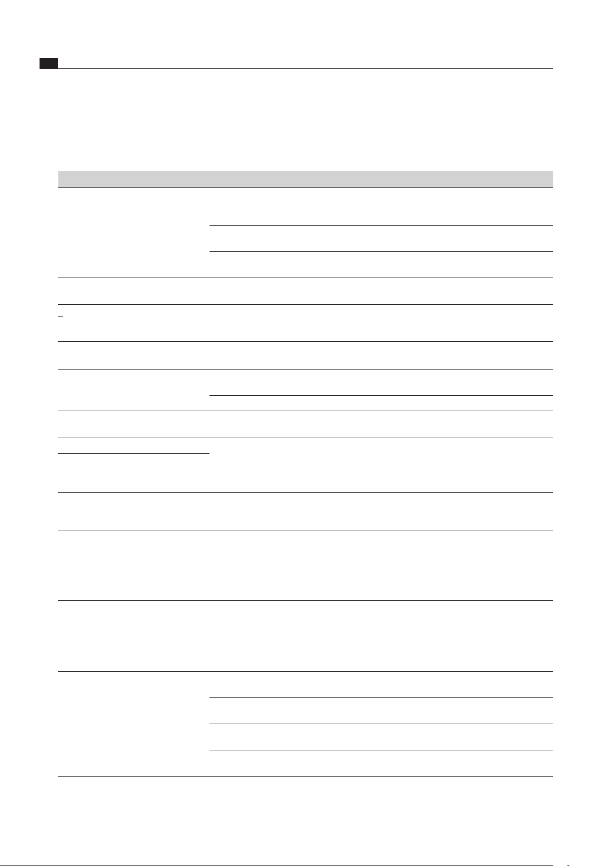
EN
38
Troubleshooting
www.bora.com
9 Troubleshooting
Observe all safety and warning information (see Safety chapter).
Operating situation Cause Remedy
The cooktop or the fan cannot be
switched on.
The fuse or the automatic circuit breaker
of the electrical installation of the
apartment and/or house is defective.
Replace the fuse.
Switch the safety cut-out back on.
The fuse or the automatic circuit breaker
trips several times.
Call the BORA Service Team.
The power supply is disconnected. Have a specialist electrician inspect the power
supply.
Odours and vapours arise when the new
cooktop is put into operation.
This is normal on brand-new
appliances.
Wait a few operating hours.
Contact the Service Team if the odour persists.
v
is displayed in the cooking zone
indicator.
No or unsuitable cooking utensils have
been placed on the cooking zone.
Only use suitable cookware.
Select the cookware size depending on the
cooking zone (see Device Description chapter).
L
is displayed in the cooking zone
indicator.
The child safety lock is activated. Switch off the child safety lock
(see Operating chapter).
A cooking zone or the entire cooktop
switches off automatically.
The operating time of a cooking zone has
been exceeded.
Put the cooking zone back into
operation (see Operating chapter).
The overheat protection has tripped. (see Device Description chapter)
The power setting is automatically
shut off prematurely.
The overheat protection has tripped. (see Device Description chapter)
E
is displayed in the fan level indicator.
One or more sensor buttons are covered,
e.g. due to finger contact or by objects
placed on them.
Clean the control panel or remove objects
(see Device description chapter).
ER03
is shown across all 4 cooking zone
indicators, and the cooktop switches off
during operation.
The cooling fan continues running after
the cooktop has been switched off.
The fan will continue to run until the
cooktop has cooled down and will then
switch off automatically.
Wait until the fan switches off automatically.
E
is displayed in the cooking zone
indicator.
An error has occurred in the
electronic system.
Interrupt the power supply of the cooktop for
approx. 1 minute.
If the problem continues to persist after the
power supply has been restored, write down
the error number and contact BORA Customer
Services.
F
is displayed in the fan level indicator.
The period of use of the filters has been
exceeded.
Replace the activated charcoal filter (only
with recirculated air) and thoroughly clean the
stainless steel grease filter. In case of heavy
soiling, replacing the stainless steel grease
filter is also recommended (see Cleaning/
Maintenance chapter).
The extraction rate of the
cooktop extractor has decreased.
The stainless steel grease filter is heavily
soiled.
Clean or replace the stainless steel grease filter.
The activated carbon filter is heavily
soiled (only BIU).
Replace the activated charcoal filter.
There is an object in the air guiding hous-
ing (e.g. cleaning cloth).
Remove the trapped object.
The fan is defective or a duct connection
has loosened.
Call the BORA Service Team.
Tab. 9.1 Resolving a fault
In all other instances, call the BORA Service Team (see the Warranty, service and spare parts chapter).
EN
39
Decommissioning, disassembly and disposal
www.bora.com
10 Decommissioning,
disassembly and
disposal
Observe all safety and warning information
(see the Safety section).
Follow the enclosed manufacturer’s information.
10.1 Decommissioning
Decommissioning is understood as final shutdown and
disassembly. Following decommissioning, the device can
either be installed into other units, sold on privately or
disposed of.
INFO Electricity and gas connections may only be
disconnected by qualified specialists.
To decommission, switch the device off
(see Operation section)
Disconnect the device from the power supply.
10.2 Disassembly
For removal, the device must be accessible for
disassembly and disconnected from the power supply.
For gas devices, make sure the gas connection is
disconnected.
Undo the mounting brackets.
Remove the silicone joints.
Disconnect the device from the extractor duct.
Remove the device from the worktop by lifting it up-
wards.
Remove any other accessories.
Dispose of the old device and any
contaminated accessories as described under
“ Environmentally-friendly disposal”.
10.3 Environmentally-friendly disposal
Disposal of transport packaging
INFO The packaging protects the device from
damage in transport. The packaging materials
have been selected from environmental and
disposal perspectives and are therefore
recyclable.
Returning the packaging to the materials cycle saves
resources and reduces waste volumes. Your specialist
supplier will take the packaging back.
Give the packaging to your specialist supplier
or
Dispose of the packaging properly in line with local
regulations.
Disposal of old appliance
Electrical devices marked with this label
may not be disposed of in domestic
waste at the end of their service
life. They must be disposed of at a
collection point for the recycling of old
electrical or electronic devices. You
can find information from your city or
district council.
Many electrical and electronic devices still contain
valuable materials. But they also contain damaging
materials which were necessary for them to function
properly and safely. These can damage human health or
the environment if disposed of improperly or incorrectly
handled.
Never put your old appliance in domestic waste.
Take the old appliance to a regional collection point
for return and recycling electrical and electronic
components and other materials.

EN
40
Warranty, technical service, spare parts, accessories
www.bora.com
11 Warranty, technical
service, spare parts,
accessories
Observe all safety and warning information
(see the Safety section).
11.1 Warranty
The warranty period is 2 years.
If you register at www.mybora.com/registration, the
warranty period is extended to 3 years.
11.2 Service
BORA Service:
see back page of operation and installation instructions
+800 7890 0987
If there are faults which you are not able to resolve
yourself, please contact your BORA specialist supplier
or the BORA Service Team.
The BORA Service Team requires the type designation
and the build number of your appliance (FD number). Both
pieces of information can be found on the nameplate on
the back of the instructions and on the appliance base.
11.3 Replacement parts
Only use original spare parts for repairs.
Repairs may only be carried out by the BORA Service
Team.
INFO Replacement parts can be obtained from your
BORA dealer, the BORA online service website
at www.bora.com/service or by calling the
service number provided.
11.4 Accessories
BFF stainless steel grease filter
BFIED air inlet nozzle
All Black BEDAB air inlet nozzle
UDB25 sealing tape
BKR760 cooktop frame
Special BIA accessories:
BUSU recirculation conversion set
BLAVH1 exhaust air duct extension
Special BIU accessories:
BAKFS activated charcoal filter
BUSAE exhaust air conversion set

EN
41
Notes:
www.bora.com
12 Notes:

EN
42
Notes:
www.bora.com


Germany:
BORA Lüftungstechnik GmbH
Rosenheimer Str. 33
83064 Raubling
Germany
T +49 (0) 8035 / 9840-0
F +49 (0) 8035 / 9840-300
www.bora.com
Austria:
BORA Vertriebs GmbH & Co KG
Innstraße 1
6342 Niederndorf
Austria
T +43 (0) 5373 / 62250-0
F +43 (0) 5373 / 62250-90
www.bora.com
Europe:
BORA Holding GmbH
Innstraße 1
6342 Niederndorf
Austria
T +43 (0) 5373 / 62250-0
F +43 (0) 5373 / 62250-90
www.bora.com
Australia - New Zealand:
BORA APAC Pty Ltd
100 Victoria Road
Drummoyne NSW 2047
Australia
T +61 2 9719 2350
F +61 2 8076 3514
www.bora-australia.com.au
Nameplate:
(please affix)
+800 7890 0987